Week-11 Challenge: Braking
AIM:
- For a defined driving cycle, calculate the energy required for braking.
- Why electric motor can’t develop braking torque at high speed similar to starting? How electric and mechanical brakes are coordinated?
- Make a MATLAB program which plots contour of given motor speed, torque and efficiency values. Attach the code as a .m file attach a screenshot of all the plots.
- For a defined driving cycle, calculate the energy required for braking.
Drive cycle is defined as a series of data points that depicts the speed of vehicle with respect to time. Different countries and organisations produces drive cycles to analyse the performance of the vehicle such as fuel consumption and polluting emissions.
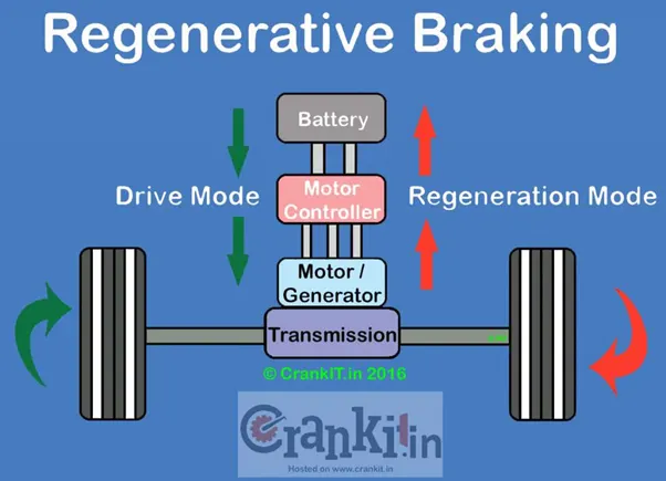
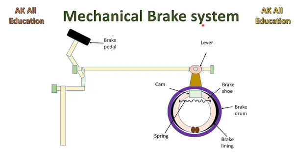
Braking system is one of the most important safety feature developed in the automobiles. The function of the braking system is to slow down the speed of the vehicle or bringing it to rest in the shortest possible distance when required. Regenerative braking is a mechanism in which energy is recovered by converting its kinetic energy into a form that can be used immediately or stored when needed. In case of regenerative braking the motor act as a generator so the kinetic energy is recovered so as to increase the energy in the battery. Regeneration can significantly extend the life of the braking system as the mechanical parts will not wear out quickly. In case of conventional braking due to friction the kinetic energy gets converted to heat energy.
FORMULAS USED TO CALCULATE THE BRAKING POWER
- Energy = 0.5*m*(Vi-Vf)^2
- Deceleration = ( Vf-Vi)/ Time taken
- Deceleration force = Mass * Deceleration * Acceleration due to gravity
- Deceleration Power = Mass * 1.5* ((Vf- Vi) ^2)/(2*t*1000)
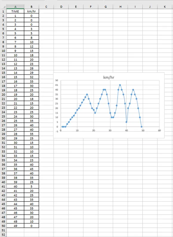
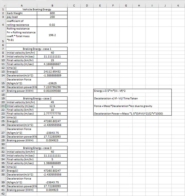
From the above drive cycle, three different situations of deceleration are considered where energy is calculated:
- First braking: 40 – 15 km/hr in 5 seconds
- Second braking: 45 – 10 km/hr in 4 seconds
- Third braking: 45 – 5 km/hr in 4 seconds
Using excel, Energy required to calculate braking are shown below:
RESULTS FOR BRAKING POWER (KWH)
- First braking: 40 – 15 km/hr in 5 seconds - 0.002009388 KWH
- Second braking: 45 – 10 km/hr in 4 seconds – 0.004923 KWH
- Third braking: 45 – 5 km/hr in 4 seconds – 0.004923 KWH
- Why electric motor can’t develop braking torque at high speed similar to starting? How electric and mechanical brakes are coordinated?
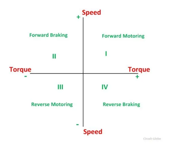
In braking mode, the motor acts as a generator and converts mechanical energy into electrical energy, it opposes the motion. So, the motor can operate in both forward and reverse direction which is motoring and braking operation.
When the motor is operated in the forward direction the speed of the motor is considered positive. The rotation of the motor in the opposite direction gives reverse speed which is denoted by a negative sign.
The rate of change of speed with respect to time in the forward direction provides acceleration which is known as positive motor torque. In case of retardation the torque developed by the motor is negative.
- QUADRANT 1
In the first quadrant the power developed by the motor is positive and supplying mechanical energy so the first quadrant operation is known as forward motoring.
- QUADRANT 2
In this quadrant the operation performed is known as braking. In this quadrant the power developed by the motor is negative as the direction of rotation is positive and the torque is negative so the motor act as a generator that opposes the motion.
CASE 1: ELECTRIC MOTOR TOOK 10 SECONDS TO REACH 0 TO 100 KMPH
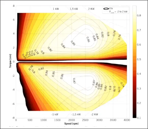
From the above graph it is observed that it is easier for the motor to reach 0 to 100 kmph in 10 seconds since at low speeds the torque maintained by the electric motor is constant and it operates in the constant torque region so the vehicle has high acceleration power at low speed the motor torque is high. So, in this case torque developed by the motor is positive and speed is also positive which falls in the first quadrant operation of the motor. Therefore, the power developed by the motor is also positive which is called as forward motoring stage.
CASE 2: ELECTRIC MOTOR TOOK 10 SECONDS TO REACH 100 TO 0 KMPH
When it comes to breaking the torque developed by the motor is negative and speed is positive so the power developed by the motor is negative which falls in the second quadrant operation of the motor. So, when compared to the first quadrant peak acceleration torque and deceleration torque are not equal since at high speed the value of torque is lower and the motor is operated in the field weaking region so the value of torque decreases. So, the breaking torque value will not be higher than the acceleration torque.
The other limitation is that the discharge rate of the battery is twice as that of the charging rate. Hence during regeneration breaking the energy saved cannot be used to charge the battery at a desired rate. Another limitation is with regenerative braking with regard to power converter as during regenerative braking a bi – directional power converter is used so as to supply the energy back from the motor to the battery which in turn increases the complexity of the system and losses occur during the conversion.
COORDINATION BETWEEN ELECTRIC AND MECHANICAL BRAKES
TYPES OF CONTROL STARTERGY
- SERIES BRAKING
In series braking mechanical brakes and regeneration brakes are applied one after the other which is applying one brake at a time. In this the break torque is passed to the brake control strategy block here the battery state of charge is checked depending upon the set of maximum permissible level of charge the battery is recharged. The brake torque is compared to the maximum regenerative torque limit of the motor generator. If the overall break torque required is less than the maximum regenerative torque then the vehicle breaks purely on regenerative torque and the battery is charged
If the overall break torque required is greater than the motor generator can provide then the mechanical brakes are applied. In a front driven car if the total torque required from front is less than regenerative torque capability of motor generator torque the front braking is provided purely on regeneration and rear by mechanical breaking. If the total break torque required is more, the front mechanical brakes are applied along with rear mechanical brakes and front regenerative brake to satisfy the overall break torque.
- PARALLEL BRAKING
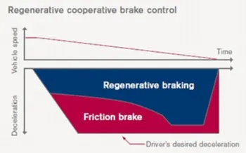
In case of parallel braking mechanical brakes and regeneration brakes are applied simultaneously. The brake torque is passed on through the brake control strategy and gets divided between regeneration and friction braking at all times
EDIB (electric driven intelligent brake) is a parallel breaking technique which is developed by Nissan leaf which uses a combination of both mechanical brake and regenerative brake.
During low speeds regenerative braking is higher and during high speeds we actually combine both.
CONCLUSION:
The breaking torque of an electric vehicle is not as high as compared to acceleration torque because of this the regenerative breaking is not as effective. Hence, we cannot get all the power back to the battery as the deceleration torque is less than the acceleration torque.
- Make a MATLAB program which plots contour of given motor speed, torque and efficiency values. Attach the code as a .m file attach a screenshot of all the plots.
clear all
close all
clc
% Determining the speed range(rad/s)
X=linspace(0,1000);
% Determinig the torqur range (Nm)
Y= linspace(0,350);
%Motor loss constants
% for copper losses
Kc=0.2;
% for Iron losses
Ki=0.007;
% for copper losses
Kw=0.00001;
% for constant motor losses
constantlosses=20;
%Speed and Torque ranges to create a 2D Array
[X,Y]=meshgrid(X,Y);
%Output Power
Poutput=(X.*Y);
%Copper losses
B=Kc.*(Y.^2);
%Iron losses
C=Ki.*(X);
%Windage losses
D=Kw.*(X.^3);
%Input Power
Pinput=Poutput+B+C+D+constantlosses;
%Efficiency
Z=Poutput./Pinput;
%Setting the efficiencies for which the contour will be plotted
V=[0.75,0.80,0.83,0.88,0.91,0.92,0.93,0.94,0.95,0.96];
%plotting the efficiency contour
grid off
contour(X,Y,Z,V)
title('Torque-speed efficiency contour')
xlabel('speed (rad/s)')
ylabel('Torque (Nm)')
hold on
% Plotting contours of output power at 8KW and 10KW
V=[8000,10000];
contour(X,Y,Poutput,V)
CODE
clear all
close all
clc
% Determining the speed range(rad/s)
X=linspace(0,1000);
% Determining the torque range (Nm)
Y= linspace(0,350);
%Motor loss constants
% for copper losses
Kc=0.2;
% for Iron losses
Ki=0.007;
% for copper losses
Kw=0.00001;
% for constant motor losses
Constant losses=20;
%Speed and Torque ranges to create a 2D Array
[X,Y]=meshgrid(X,Y);
%Output Power
Poutput=(X.*Y);
%Copper losses
B=Kc.*(Y.^2);
%Iron losses
C=Ki.*(X);
%Windage losses
D=Kw.*(X.^3);
%Input Power
Pinput=Poutput+B+C+D+constantlosses;
%Efficiency
Z=Poutput./Pinput;
%Setting the efficiencies for which the contour will be plotted
V=[0.75,0.80,0.83,0.88,0.91,0.92,0.93,0.94,0.95,0.96];
%plotting the efficiency contour
grid off
contour(X,Y,Z,V)
title('Torque-speed efficiency contour')
xlabel('speed (rad/s)')
ylabel('Torque (Nm)')
hold on
% Plotting contours of output power at 8KW and 10KW
V=[8000,10000];
contour(X,Y,Poutput,V)
EXPLANATION
- Linspace command is used to create arrays for speed and torque of the motor. For speed the values are ranging from 0 to 1000 radians per second and torque values ranging from 0 to 350Nm.
- Arrays are then used to create 2D grid coordinates using the meshgrid command. These coordinates help in the creation of the contour.
- In order to improve the efficiency of the motor various losses that occur during motor operation are considered the losses are:
- COPPER LOSSES
Copper losses are due to the heat produced by electrical currents in the conductors of transformer windings.
Copper loss ∝ I2 R
Where R is the armature resistance and current is directly proportional to Torque and then by considering a constant for copper loss.
Copper loss =Kc T2
- IRON LOSSES
Iron losses are mainly due to magnetic field effect. Iron losses consists of three components namely eddy current losses, hysteresis losses and anomalous losses. These losses vary depending upon the speed of the motor and then by considering a constant for iron losses.
Iron losses = ki ω
- WINDAGE LOSSES
These windage losses are due to mechanical and frictional losses experienced by the motor. It depends upon the shape and size of the motor. the following equation is given by:
Windage losses = kw. ω3
- CONSTANT LOSSES
These types of losses always occur irrespective of the load condition and the value always remain constant for a given machine. It is represented by C
- These different types of losses depend upon the speed and torque of the motor and the loses have constant of proportionality which are assumed for calculation which is denoted by the letter K
- The input power is calculated by adding all the losses plus the output power and the efficiency of the motor is calculated by output / input
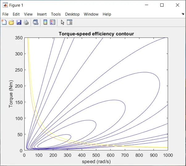
- Finally, the contour plot of speed torque characteristics of the motor is plotted using the contour command. An array of efficiency values is plotted and denoted by V and the values are ranging from 0.75 to 0.96.
- This array helps in creation of the contour and the x axis and y axis are labelled as speed and torque respectively.
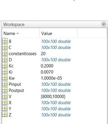
WORKSPACE DATA
RESULTS