Week-11 Challenge: Braking
QUESTIONS
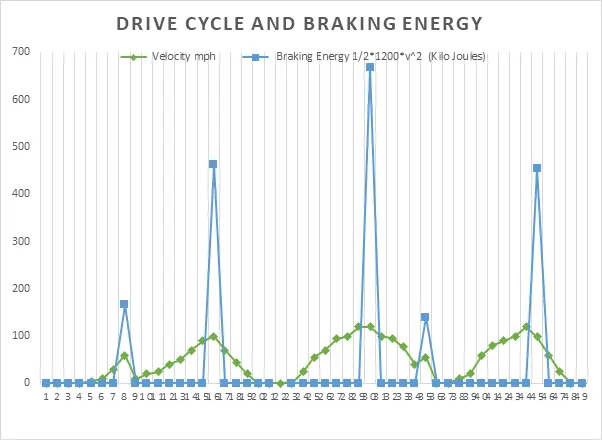
- For a defined driving cycle, calculate the energy required for braking.
- Why electric motor can’t develop braking torque at high speed similar to starting? How electric and mechanical brakes are coordinated?
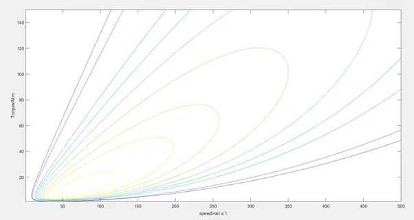
- Make a MATLAB program which plots contour of given motor speed, torque and efficiency values. Attach the code as a .m file attach a screenshot of all the plots.
ANSWERS
ANS 1:
Considering a drive cycle with various braking intervals and hence calculating the braking energy required at corresponding braking interval.
Consider mass of vehicle m = 1200 Kg.
We know the braking energy when brakes are applied while vehicle is in motion is given by
`E_b=1/2 ×mv^2`
DRIVE CYCLE DATA WITH BRAKING ENERGY CALCULATION
|
Time |
Velocity m/s |
Velocity mph |
Braking Energy ½*m*v^2 (Kilo Joules) |
|
0 |
0.00 |
0 |
0 |
|
1 |
0.00 |
0 |
0 |
|
2 |
0.00 |
0 |
0 |
|
3 |
0.00 |
0 |
0 |
|
4 |
1.39 |
5 |
0 |
|
5 |
2.78 |
10 |
0 |
|
6 |
8.33 |
30 |
0 |
|
7 |
16.67 |
60 |
166.6666667 |
|
8 |
2.78 |
10 |
0 |
|
9 |
5.56 |
20 |
0 |
|
10 |
6.94 |
25 |
0 |
|
11 |
11.11 |
40 |
0 |
|
12 |
13.89 |
50 |
0 |
|
13 |
19.44 |
70 |
0 |
|
14 |
25.00 |
90 |
0 |
|
15 |
27.78 |
100 |
462.962963 |
|
16 |
19.44 |
70 |
0 |
|
17 |
12.50 |
45 |
0 |
|
18 |
5.56 |
20 |
0 |
|
19 |
0.00 |
0 |
0 |
|
20 |
0.00 |
0 |
0 |
|
21 |
0.00 |
0 |
|
|
22 |
0.00 |
0 |
0 |
|
23 |
6.94 |
25 |
0 |
|
|
|
|
|
PLOT
.
.
.
ANS 2:
Regenerative braking
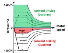
Regenerative braking takes place whenever the speed of the motor exceeds the synchronous speed. This baking method is called regenerative braking because here the motor works as generator and supply itself is given power from the load, i.e. motors. The main criteria for regenerative braking is that the rotor has to rotate at a speed higher than synchronous speed, only then the motor will act as a generator and the direction of current flow through the circuit and direction of the torque reverses and braking takes place.
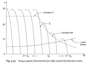
Sometimes after accelerating you can't reach the maximum torque. The reason is that no matter how much the current loop wants to increase current (proportional to torque) by increasing the PWM duty cycle of the power stage, the Vmotor is too close to Vbemf and therefore current can't increase more. This situation does not occur at the beginning of an acceleration because most of the torque is used to increase the kinetical energy of the load (and motor). But when the speed is already high and no extra load is applied it is not possible to increase the torque.
Peak Acceleration Torque and Peak Deceleration torque are not equal for Electric Vehicle Motor. So the Peak Torque during acceleration and the Peak torque during deceleration or braking are not equal. Acceleration is usually higher, at low speed we get higher Torque but high speed the value of the torque gets lower. So we cannot say that the motor which is producing 7Nm Torque for Acceleration can also produce -7Nm of Braking Torque. So becaue we Operating the Motor in Field Weakening region or we are operating the Motor above base speed we must know that the torque is compromised or the torque value is lower. So Electric motor can't develop braking torque at high speed similar to starting, because Braking Torque of an EV Motor is not as high as the Acceleration Torque. Therefore, Regenerative braking is cannot happen so effectively that we can get all the power back to the battery.
Coordination Control Strategy for Mode Switch in braking
According to whether or not the hydraulic braking system is involved in braking, the braking mode-switch type is divided into two categories. Braking mode-switch coordination control strategies are developed for the different braking mode-switch types.
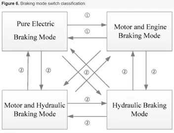
1) Type one: braking mode switch without hydraulic braking system participation. In this type of mode switching it is necessary to control the engagement of the clutch and the change rate of the motor torque. Thus, the fluctuation caused by mode switch can be reduced.
(2) Type two: braking mode switch with hydraulic braking system participation. Due to the different dynamic response characteristics of the motor and the hydraulic braking systems, this switch mode is difficult to coordinate. The idea of coordinating control is to take full advantage of the characteristics of the braking systems. The hydraulic system can provide large and stable torque, and the motor braking system’s torque response is quick and accurate, reducing the fluctuation
Coordination Control Strategy of Type One
In this type of mode switch the motor braking torque and the engine drag resistance torque, transmitted by clutch II, are the main sources of braking torque fluctuation. Therefore, the braking torque fluctuation is coordinated by controlling the change rate of the clutch hold-down force and the motor brake force.
Coordination Control Strategy of Type Two
The dynamic response of the hydraulic braking system is slow and stable while the response of the motor braking system is fast and accurate. The hydraulic brake system has been developed for a long time, its technology is mature and stable, and its dynamic response characteristics have been well researched. Therefore, in order to make full use of the characteristics of the motor and the hydraulic braking systems, the coordinated control process of braking mode switch is divided into two stages; this is achieved by modifying the target braking torque
References
https://www.mdpi.com/1996-1073/10/11/1684/htm
.
.
.
ANS 3:
Copper loss-`I^2 R`:where R is Armature resistance and torque is proportional to current, the copper loss can be considered as `k_c.T^2` where `k_c`is to take care of resistance of brushes and also take care of flux and its effect.
Cu losses = `k_c.T^2`
Iron loss: Iron losses are nothing but magnetic losses, which is denoted by `k_i.ω`, where Ki factor is based in the magnetic field effect. For permanent magnets have constant magnetic field and this iron losses is based on the value of Ki and this are going to change according to the speed. At Various speed have different value of back EMF and that is going to affect the iron losses
Iron losses=`k_i.ω`
Windage losses: This is mechanical or friction of windage losses. This is based on size of shape of motor and the amount of windage losses that the motor is going to experience.
Windage losses =`k_w.ω^3`
Total losses : The Total losse are considering the above four losses and denoted as,
Total losses= `k_c.T^2+k_i.ω+k_w.ω^3+C`
All motors are model as per the above equation of losses.
MATLAB PROGRAM TO PLOT THE MOTOR-SPEED-TORQUE CONTOUR EFFICIENCY:
%to plot efficiency contour sor electric motors
%let X-axis denote the speed of the motor w
%Y-axis torque T
X=linspace(1,500);
Y=linspace(1,150);
%motor loss constants
Kc=0.5;
Ki=0.004;
Kw=0.00012;
constloss=15;
%making mesh
[x,y]=meshgrid(X,Y);
outputpow=(x.*y);
B=(y.^2)*Kc;
C=x*Ki;
D=(x.^3)*Kw;
inputpow=outputpow+B+C+D+constloss
z=outputpow./inputpow;
v=[0.6,0.63,0.7,0.725,0.75,0.775,0.8,.82,0.85,0.9,0.925,0.95,0.97,0.99];
box off
grid off
contour(x,y,z,v);
xlabel('speed/rad.s^-1')
ylabel('Torquw/N.m');
PLOT