Week 11 Challenge
Aim : To calculate the temperature load for the R.C bridge with M 40 grade to be constructed in Delhi.
Given data :
- The box girder dimension is 1500 x 1500 with a web thickness 300 mm
- Span of bridge is 9 m
- The dia of circular pier is 2.5 m
- The width of deck slab is 7 m and width of pier cap is 6 m
- Thickness of deck slab is 550 mm
Theory :
Amount of heat (sensible and latent) energy to be removed from an inner environment by the refrigeration equipment to maintain that environment at the design temperature when worst case external temperature is being experienced.
Calculation:
Max temperature in location as per IRC 6 at the location is 48.4°
Min temperature in location as per IRC 6 at the location is -2.2°
Effective temperature difference = ( 48.4 – ( -2.2) ) / 2 + 10 = 35.3°
Stress due to temperature = ɑ x Δ T x E
= 11.27 x 10^-6 x 35.3 x 5000 ( 40 )0.5
Stress due to temperature = 12.58 kn/m^2
Max permissible stress = ( 2/3 ) x 0.7 x (40)0.5 = 2.92 kn/m2
Positive temperature difference
Temperature at top = 48.4°
Temperature at bottom = (2.1/17.8) x 48.4 = 5.71°
Aim : To prepare the model in a STAAD Pro and perform the analysis and justify with the results.
Theory : The general steps to be create a STAAD Pro model is given below,
Step 1 : Create the nodes by using the nodes cursor.
Step 2 : Joining the nodes by using the respective beam plate cursor.
Step 3 : Supports given to the nodes whether its pinned or fixed or any other custom supports
Step 4 : specifications given to the respective beams plates Step 5 : Assign the dead load as per calculation
Step 6 : Save the model and perform the analysis
Step 7 : The results are obtained and discuss with the results
Step 8: Take the print out of report of necessary results.
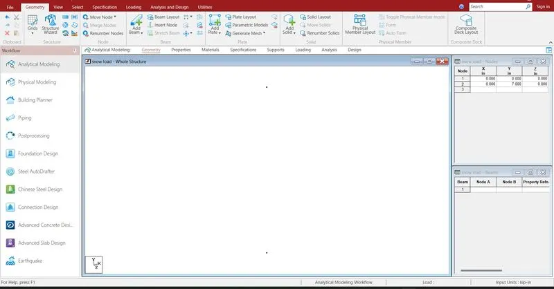
Creating the nodes by using node cursor.
Open the STAAD Pro window > Select > Node cursor > enter the value with respect to X Y Z axis > click enter
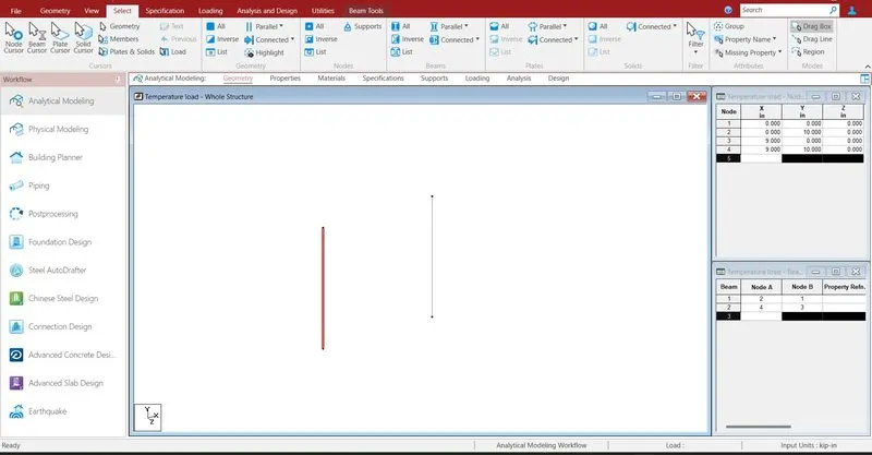
Join the nodes by using beam cursor.
Select > beam cursor > join by dragging the mouse or enter the node numbers > click enter
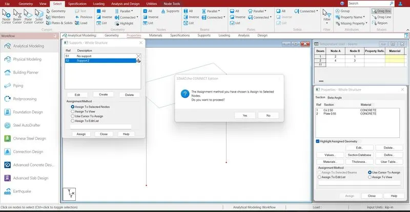
Supports are given to the respective nodes.
Specifications > Supports > select the supports > click enter
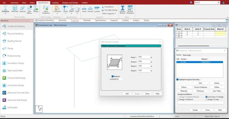
Assigning the properties to the beam .
Specification > Prismatic > Rectangle > enter dimensions > select the beam > assign the properties to selected beams.
Specification > Plate thickness > enter dimensions > select the plates > assign the properties to selected plates
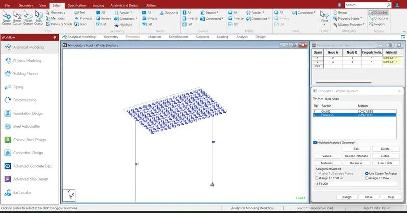
Assigning properties to the plates.
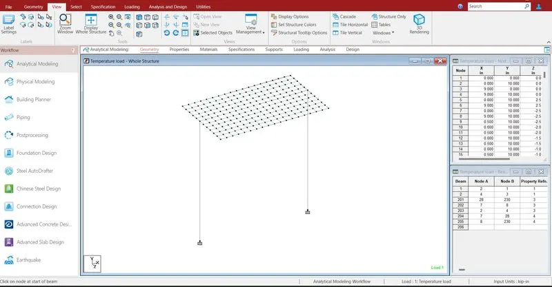 model has been prepared and all properties are assigned.
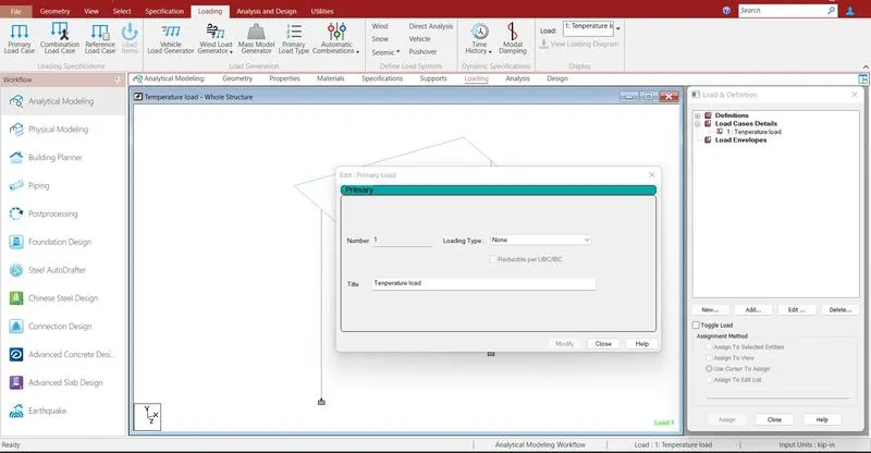
Defining the load cases .
Loading > Load case detail > temperature load > select load > Add
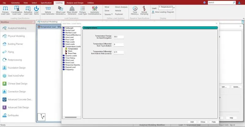
Add > temperature load > enter the value > ok
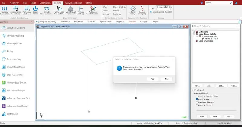
Select the defined load > Assign to view > click enter
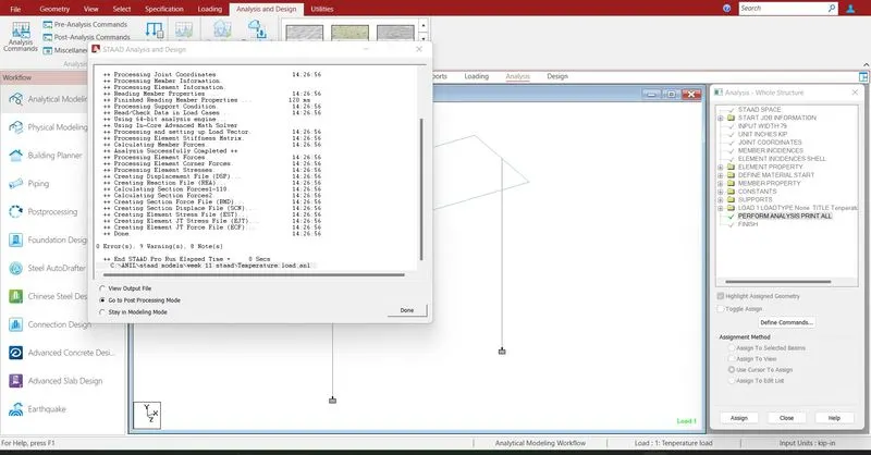
Run analysis > go to post processing mode > Results
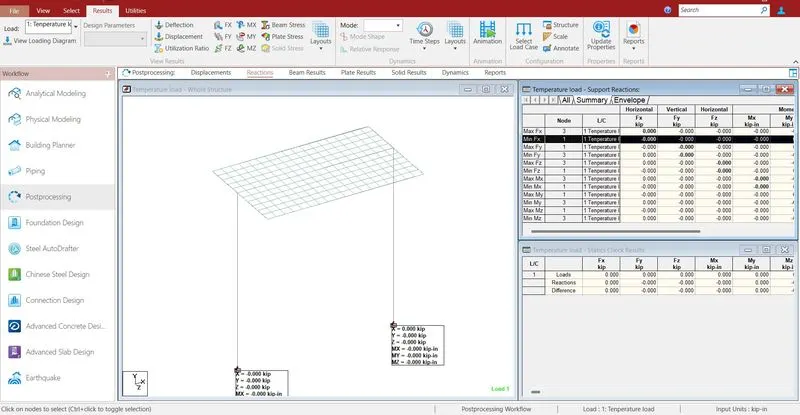
The reactions are generated at the end of the nodes .the reaction is nill.
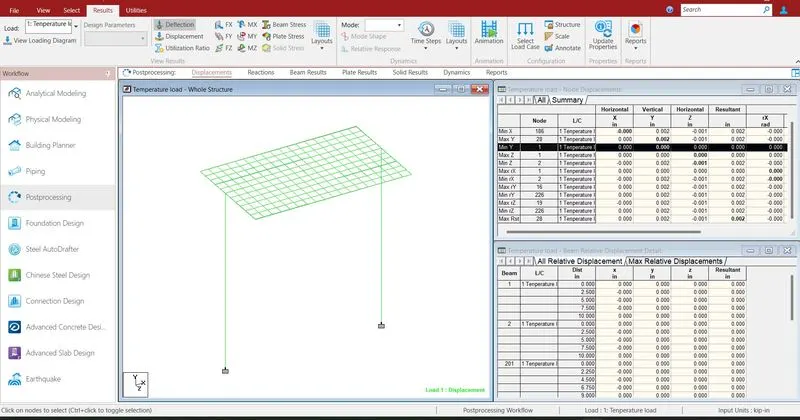
- The maximum deflection in X direction is 0 mm
- The minimum deflection in X direction is 0 mm
- The maximum deflection in Y direction is 0 mm
- The minimum deflection in Y direction is 0 mm
- The maximum deflection in Z direction is 0 mm
- The minimum deflection in Z direction is 0 mm
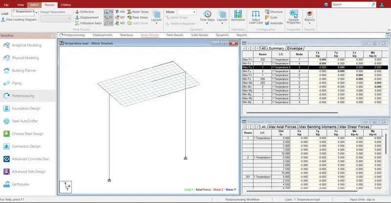
- The maximum shear force in X direction is 0 KN
- The minimum shear force in X direction is 0 KN
- The maximum shear force in Y direction is 0 KN
- The minimum shear force in Y direction is 0 KN
- The maximum shear force in Z direction is 0 KN
- The minimum shear force in Z direction is 0 KN
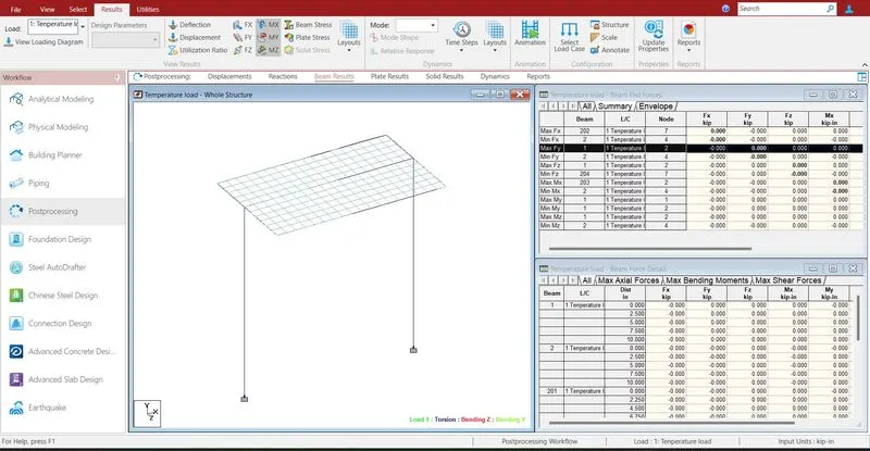
- The maximum bending moment in X direction is 0 KN-m
- The minimum bending moment in X direction is 0 KN-m
- The maximum bending moment in Y direction is 0 KN-m
- The minimum bending moment in Y direction is 0 KN-m
- The maximum bending moment in Z direction is 0 KN-m
- The minimum bending moment in Z direction is 0 KN-m
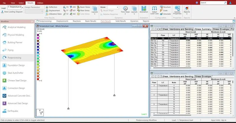
- The maximum shear stress in X direction is 0 KN/m2
- The minimum shear stress in X direction is 0 KN/m2
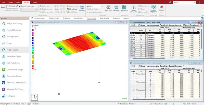
- The maximum shear stress in Y direction is 0 KN/m2
- The minimum shear stress in Y direction is 0 KN/m2
- Reports are taken printout which ever is necessary by using report
- In the report option we obtain the results of section forces, displacement, reactions, plate
- The exact report is to be taken further move to design