Week 11 Challenge
1)
Aim: To determine the friction load of A pipe carrying LNG that rests on the shoe having a vertical force of 125 kN. Friction load on the axis and friction force are required to be determined if there is a TEFLON pad between the shoe and pipe support.
Procedure :
Friction factor/Coefficient and friction load on piping:
Friction Factor of Steel to Steel = 0.3
Friction Factor of Teflon to Steel = 0.1
Step 1: When Steel pipe is resting on steel:
Friction force in the longitudinal direction (Ff) = Coeff of friction x Gravity Load
= 0.3 x 125 kN = 37.5 kN
Friction load in transverse direction = 10% of piping operating load
= 0.1 x 125 = 12.5 kN
Step 2: When the Steel pipe is resting on Teflon :
Friction force in the longitudinal direction (Ff) = Coefficient of friction x Gravity Load
= 0.1 x 125 kN = 12.5 kN
Friction load in transverse direction = 10% of piping operating load
= 0.1 x 125 = 12.5 KN
Result: Friction load in the longitudinal and transverse directions are 37.5 KN & 12.5 KN respectively when the pipe is resting on steel. These friction forces are 12.5 KN & 12.5 KN respectively when the pipe is resting on Teflon.
2)
Aim: To identify the type of support as Spring, Guyed, Stop or Semi Anchor (Guyed + Rest + Stop ) or Rigid Strut from the following images.
Types of Supports:
- Spring Support: Permit the pipe to move in the vertical direction
- Rigid Support: Allow small angular displacement and thermal movement.
- Stop support: Restrained the movement of pipe in the axial direction but allow the pipe movement in the lateral direction
- Semi Anchor Support: Restrict the pipes to move in axial as well as transverse directions.
- Guyed support: Restrained the lateral movement in two directions therefore also limits the rotational movement of pipe but permits axial movement of the pipe
- Anchor Support: It does not permit the pipe to move in any direction thus movement in all 6 degrees of freedom is restricted.
Support Identification:
Figure 1
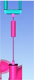
Types of Support: Spring Support.
Figure 2
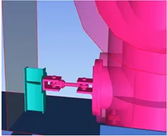
Types of Support: Rigid Support.
Figure 3
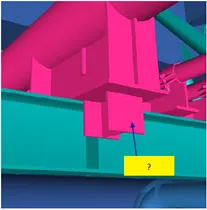
Types of Support: Stop support.
Figure 4
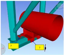
Types of Support: Semi Anchor Support.
Figure 5
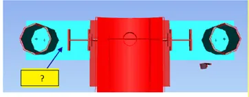
Types of Support: Guyed Support.
Figure 6
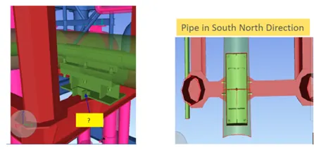
Types of Support: Anchor Support.
Result: Supports are identified as Spring, Guyed, Stop or Semi Anchor (Guyed + Rest + Stop ) or Rigid Strut from the above images.
3)
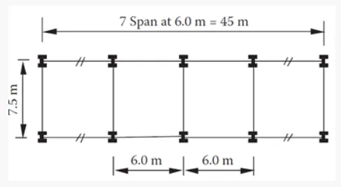
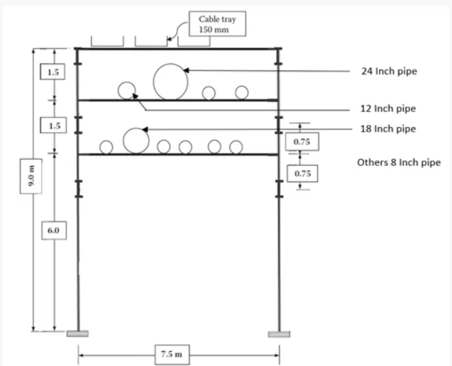
Aim: To design a typical pipe rack bent in an oil plant. The pipe rack configuration and the plan layout are shown in figure below.
Given Data:
Height of Column = 9 m
Height of First-tier = 6 m
Height of Second tier = 7.5 m
Height of Third tier = 9 m
Width of Pipe Rack = 7.5 m ( C/C of Column in width of pipe rack)
The span of each Bay = 6 m
Number of bays = 7
The top tier of the pipe rack has 3 nos cable trays each 150 mm wide.
The second tier of the pipe rack has 4 pipes, one of 24" diameter and one of 12" diameter,
The remaining two pipes are of dia 8"
The first tier of pipe rack has 6 pipes, one of 18 " diameter, and remaining 5 pipes are of dia smaller than 8".
Plan View:
Elevation View:
Procedure:
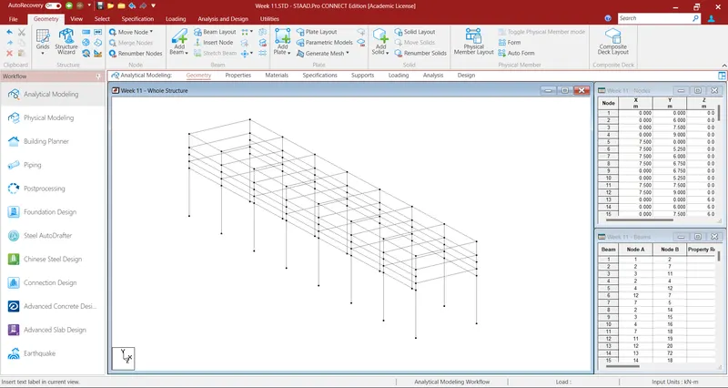
Step 1: Open a new Staad file and model the basic structure as per instructions.
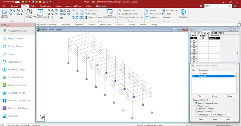
Step 2: Now add fix supports to all columns.
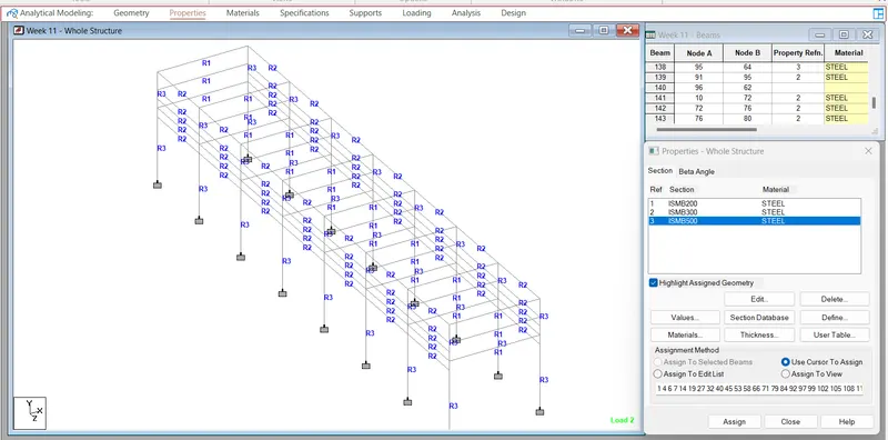
Step 3: Now add section properties to the material.
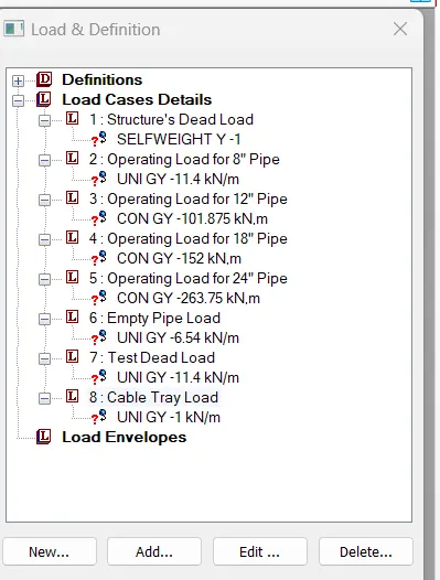
Now add loading to the pipe rack
a. Add Dead load of the structure
- Self-weight
b. Add Operating Dead Load
- Weight of pipe including fluid and insulation
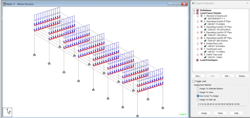
- UDL of 1.9 kN/m for pipe of dia 8"
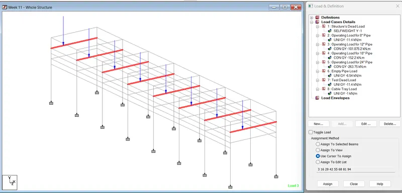
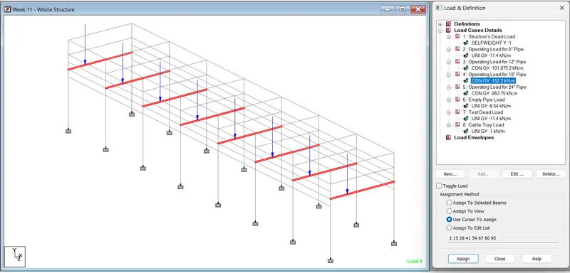
- Point load at locations where the pipe is larger than 8" dia pipes which will be reported by Piping Engineer.
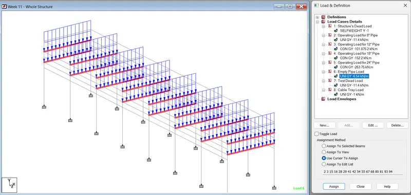
c. Empty Dead Load
- The weight of an empty pipe without fluid in it but including insulation is assumed as 60% of the operating load.
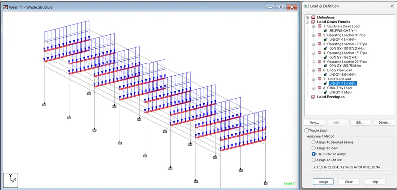
d. Test Dead Load
- In case of test medium in the pipe is not known, water with a density of 1000 kg/m3 is considered as the test medium so generally, test load is the same as operating dead load.
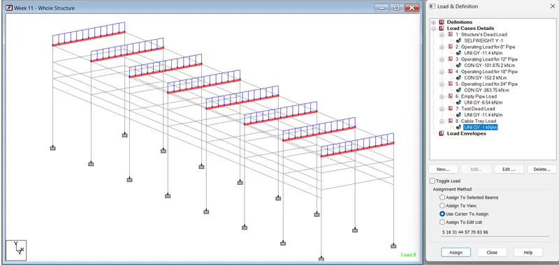
e. UDL of 1 kN/m is considered.
Step 5: Apply these loadings to the model.
1. Structure Self-weight
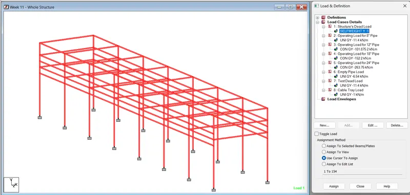
2. Operating Load for 8" Pipe
3. Operating Load for 12" Pipe
4. Operating Load for 18" Pipe
5. Operating Load for 24" Pipe
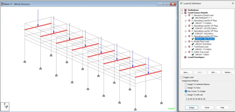
6. Empty Pipe Load
7. Test Dead Load
8. Cable Tray Load
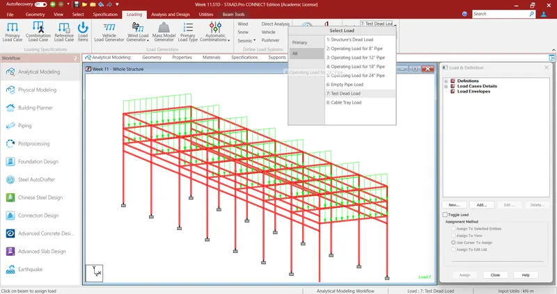
Step 6: Now run the analysis and check for errors if any.
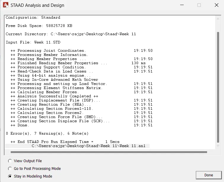
Result: The Given Pipe rack has been modeled in the Staad Pro, with the given Dimensions, Loading, Support, and Specifications, also the analysis of the Pipe has been done successfully and Zero Error has been found.