Week 11 Challenge
Q1. Design the pile of the below mentioned bridge . considering 28 m straight span.
- With abutment having backfill
- With abutment having RE wall.
Vertical capacity-250 tonne horizontal capacity -40 tonne
Soln :
PDF files with manual calculation attached in the attachment.
Q 2)List out different components of pile foundations and calculate kg/cumec (poundage) steel quantity in the pile.
Soln :
The main components of the foundation are the pile cap and the piles. Piles are long and slender members which transfer the load to deeper soil or rock of high bearing capacity avoiding shallow soil of low bearing capacity The main types of materials used for piles are Wood, steel and concrete.
DESIGN OF TWO PILE CAP
ASSUMPTION DATA:-
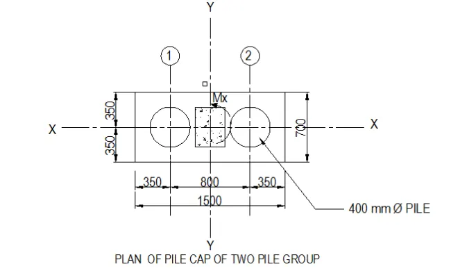
Pile Diameter : 400 mm
Spacing of piles 2 hp = 2 x 400 : 800 mm
Column Dimension B x D : 300 x 450 mm
Factored Load : 1072.8 KN
Factored Moment Mxu :51.29 KN.m
Safe Load on Single Pile :500KN
Concrete Mix : M20
Steel Grade : Fe 415
DESIGN : -
1. Pile Cap Dimension :
Breadth of Pile Cap = C/c of Pile + hp /2+ 150 + hp /2 + 150
= 800 + 400/2+ 150 +400/2+ 150 =1500 mm
Width of pile cap = hp + 150 + 150 = 700 mm
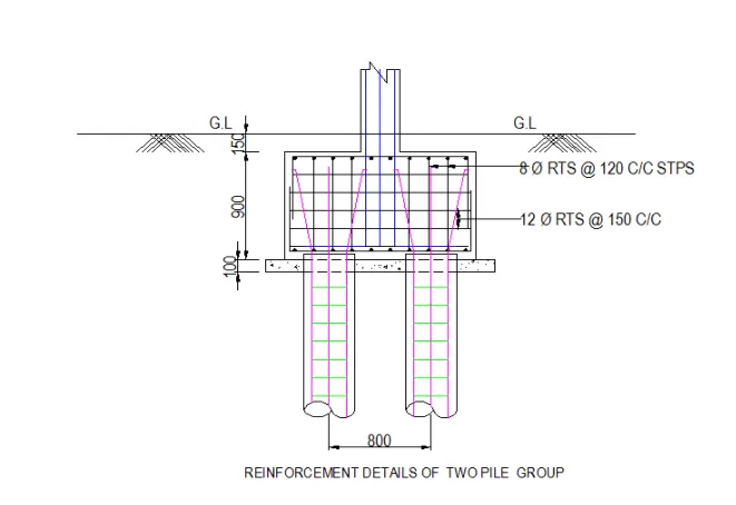
Depth of Pile cap = 2 hp + 100 = 2 x 400 + 100 = 900 mm
2. Check for Pile Load capacity :-
Total factored axial compressive load
= Pu/n +/- Mxy/∑y^2 +/- Mxx/ ∑x^2
Self weight of Pile Cap = (1.5 x0.7 x 0.9 x 25 ) x1.5 = 35.45 KN
Factored load from column Pu = 1072.80 KN
Total Factored Load Pu = 1108.25 KN
No. of Piles along one side of axis = 2
y coordinate of Pile cap = 0.4 m
Mx = Moment about x axis = 51.29 KN.m
Compressive load in A1 & A2 about x – x axis
= 1108.25/2 + 51.29 x 0.4/(2 x 0.42)
= 554.13 + 64.11
=618.24 KN
Design working load = 618.24 /1.5 = 412.16 KN < Safe Load on Pile i.e
500KN. O.K.
3. Bending Moment :-
Factored Moment in section Y-Y
Mu = 618.24 x (0.8-0.3)= 154.56 KN.m
4. Check for effective depth :
Mu = 0.138 fck b d2 = 154.56 x 10⁶
d required = √ (154.56 x 10⁶ ) / 2.76 x700 =282.84 mm
D provided = 900 mm
d available = 900 – 60 -12- 6 = 822 mm > d required i.e. 282.84 mm
5. Check for Punching Shear (Two way shear) : -
Punching shear at a distance d/2 (i.e.822/2= 411mm) from face of column
= 1072.80 KN
The critical section of punching comes the centre of pile.
Hence the net load is to be taken. However the depth is checked for factored
axial load from column = 1072.80 KN
b= 700 x 822 mm
d= 822 mm
Perimeter of critical section = 2 (700 + 822) = 3044 mm
Punching shear stress = (1072.80 x 10^3)/3044 x 822
= 0. 43 N/mm2
Allowable shear stress for M20
= 0.25 √fck = 0.25 √20 = 1.12 N/mm2
Hence safe.
6. Main Reinforcement : -
Mu = 154.56 x 10⁶ KN.m
K = Mu / bd2
= 154.56 x 10^6/700 x 822^2= 0.33
Pt from Table 2 of Design Aid=0.11
Minimum Ast = (0.12/100) x 700 x 822 = 690.48 mm2
Provide 7 Nos. 12 Φ RTS at bottom on both ways.
(Ast = 791 mm2
> 690.48 mm2
Reinforcement at top :-
Minimum Ast = 0.12 x 700 x 822 = 690.48 mm2
Provide 7 Nos. 12 mm Dia RTS at top .
(Ast = 791 mm2
> 690.48 mm2
7. Check for one way shear :-
Maximum Shear force at face of column = 618.24 KN
Shear stress = (618.24 x 10³)/(700 x 822) = 1.07 N/mm2
For Pt = 0.20%
ζc from Table 61 of Design Aid to IS 456 -1978 = 0.33 N /mm2
Shear to be carried by stirrups shear
Vus =(1.07– 0.33) x700 x822 x 10^-3
= 425.80 KN.
Vus /d = 425.80 / 82.2 = 5.18 KN/cm
Provide 8 Φ RTS 4 legged stirrups @ 120 mm c/c.
(Vus /d =5.58 KN/m > 5.18 KN/cm )