Week 11- Assembly Workbench
INTRODUCTION
Assembly modeling is a technology and method used by computer-aided design and product visualization computer software systems to handle multiple files that represent components within a product. The components within an assembly are represented as solid or surface models.
OBJECTIVE
To create assemblies of Quick return mechanism and CV joint and to also create 2D drawing of the given assemblies in CATIA.
METHODOLOGY
First step is to model the different parts of quick return mechanism and CV joint according to the drawing.
Then to assemble the parts open the assembly workbench and insert or copy the parts for the assembly.
Then give constraints to different parts accordingly.
Then we go to the drawing workbench and do 2D drafting of the assembly.
DESCRIPTION
Assembly-
Assembly modeling is a technology and method used by computer-aided design and product visualization computer software systems to handle multiple files that represent components within a product. The components within an assembly are represented as solid or surface models.
Assembly drawing is a presentation of a structure or product with its components connected together, in their relative working positions while in use
The vast majority of the designed assemblies consist two modelling strategies, bottom-up technique and top-down technique.
Bottom-up technique-
Bottom-up is the most traditional method used. Parts are modeled and them are inserted into the assembly using mates to position and fix them in relation to other components. Any changes to a part will need to be done by editing it individually.
Top-down technique-
Top-down methods allow an engineer or designer to control the design in one location. ... Instead of needing to open all files within the design to perform updates, all dimensions can be changed in the one file, updating the entire assembly with ease.
Quick return mechanism assembly-
First we model all the different parts of the Quick return mechanism assembly given to us as in the drawing.
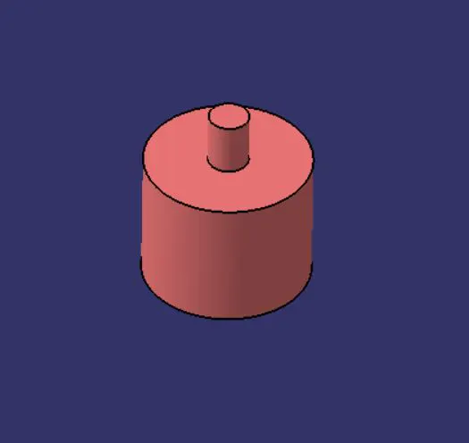
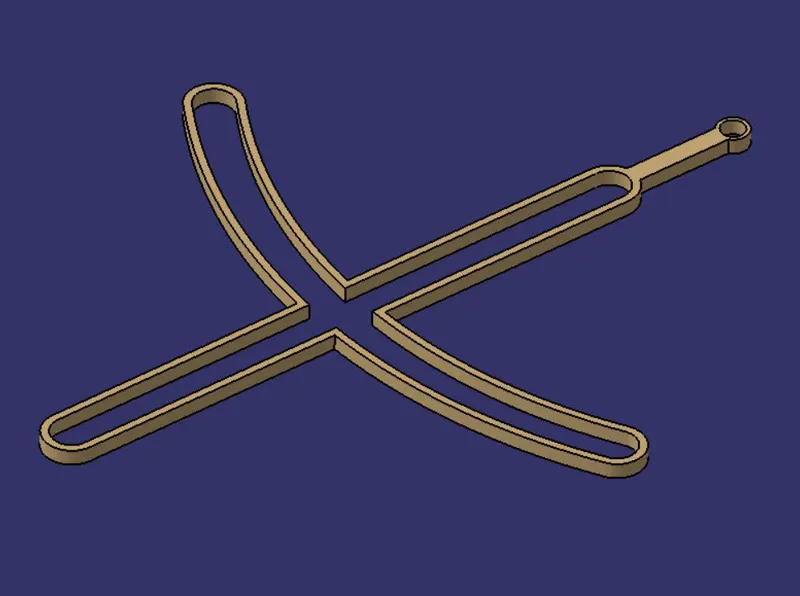
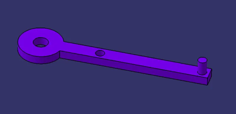
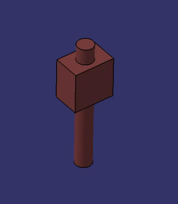
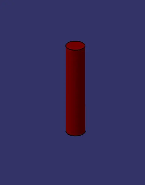
After modelling all the parts we open the assembly workbench or a new product window.
In that workbench we can either copy and paste the component or part which is opened in another window or just use the insert part tool too insert the part in the workbench.
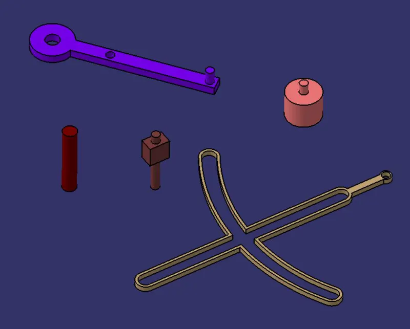
After inserting all the components we make a skeleton reference with all the planes and a point which would be the base or act as the main plane for the product with all the component.
We then start giving constraints to the parts of the assembly.
We fix the skeleton reference so that it would be at a fixed place. Then according to this we will give constraints to others.
The constraint we give to the parts and components should be mostly a reference element and not contact surface. Contact surface should be avoided if possible since if there is any design changes then at that time it would cause error.
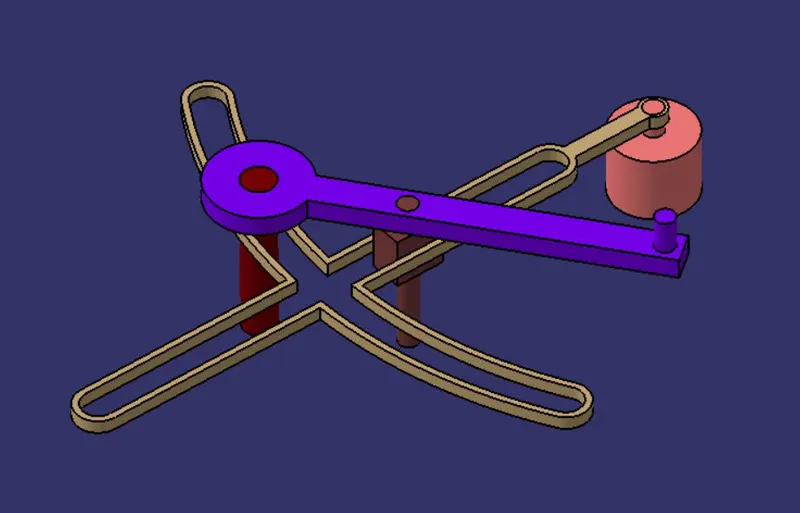
After giving all the constraints we save the assembly using save management with the help of which we can save all the modified components too.
Then we open the drawing workbench to make a 2D drawing of the Quick return mechanism assembly and its components.
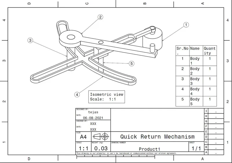
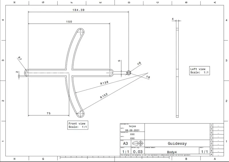
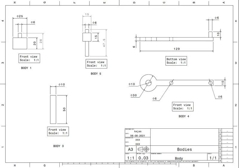
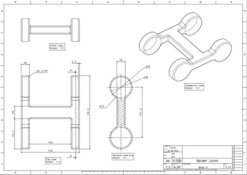
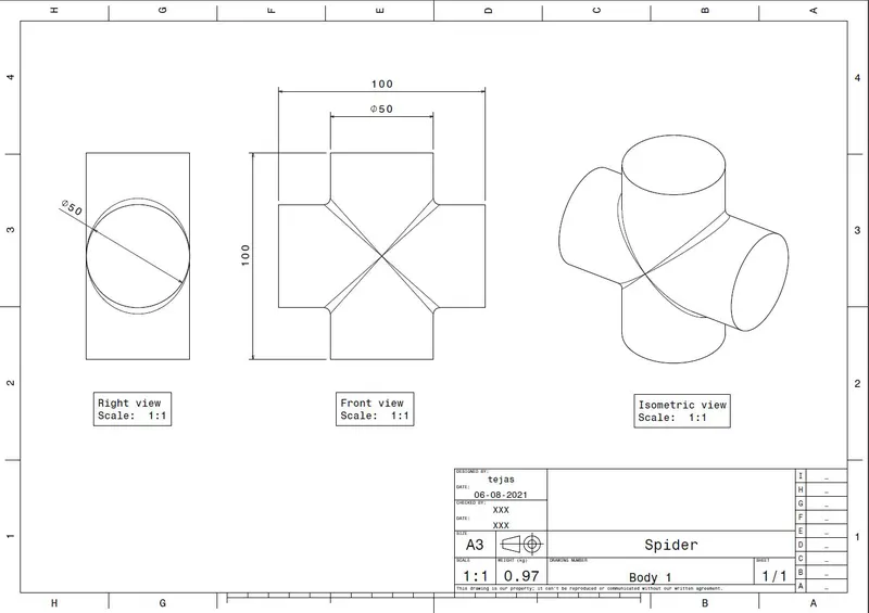
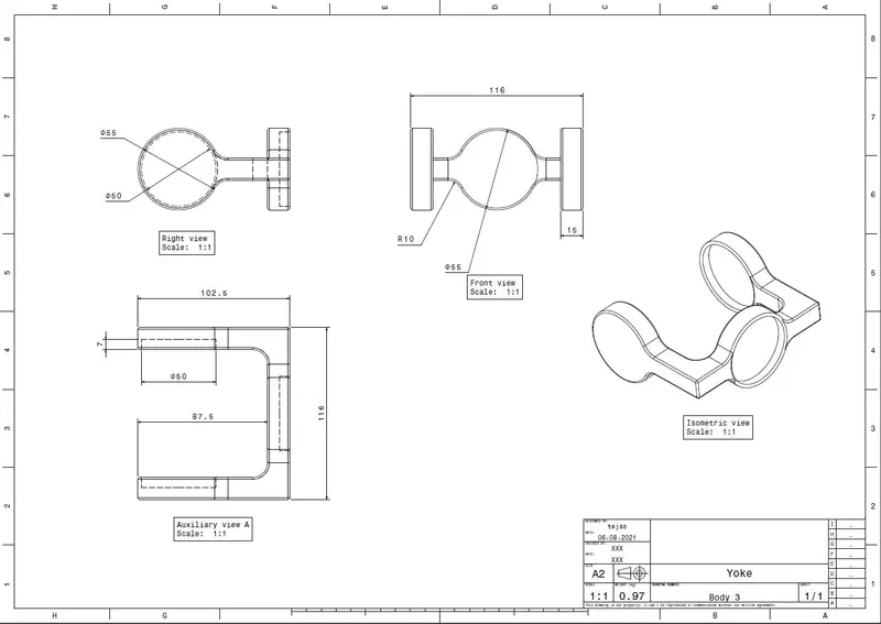
CV joint assembly-
First we model all the different parts of the CV joint assembly given to us as in the drawing.
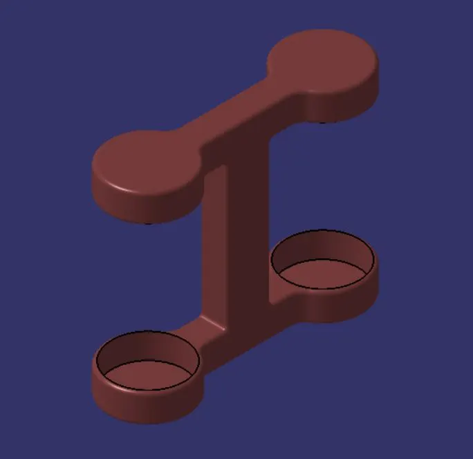
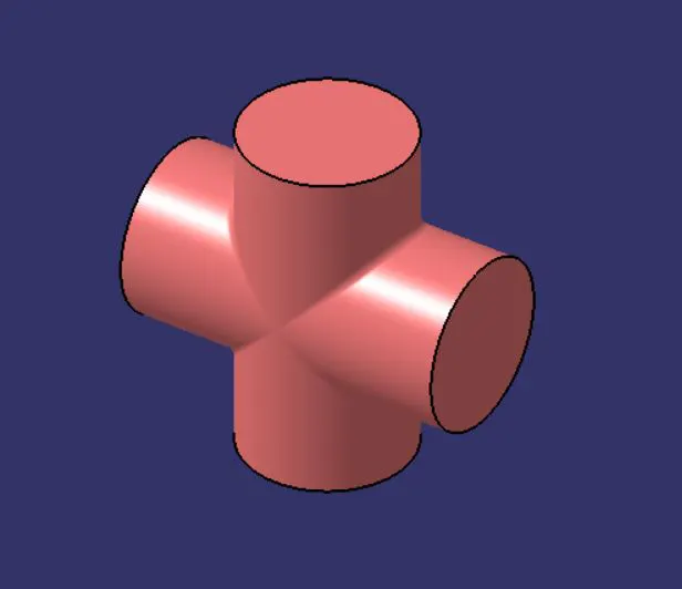
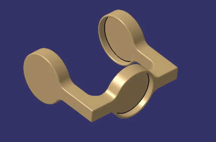
After modelling all the parts we open the assembly workbench or a new product window.
In that workbench we can either copy and paste the component or part which is opened in another window or just use the insert part tool too insert the part in the workbench.
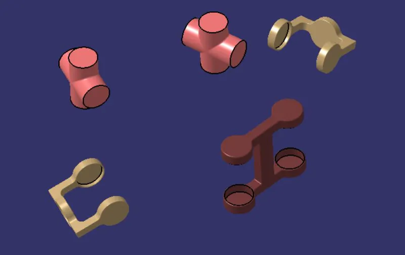
After inserting all the components we make a skeleton reference with all the planes and a point which would be the base or act as the main plane for the product with all the component.
We then start giving constraints to the parts of the assembly.
We fix the skeleton reference so that it would be at a fixed place. Then according to this we will give constraints to others.
The constraint we give to the parts and components should be mostly a reference element and not contact surface. Contact surface should be avoided if possible since if there is any design changes then at that time it would cause error.
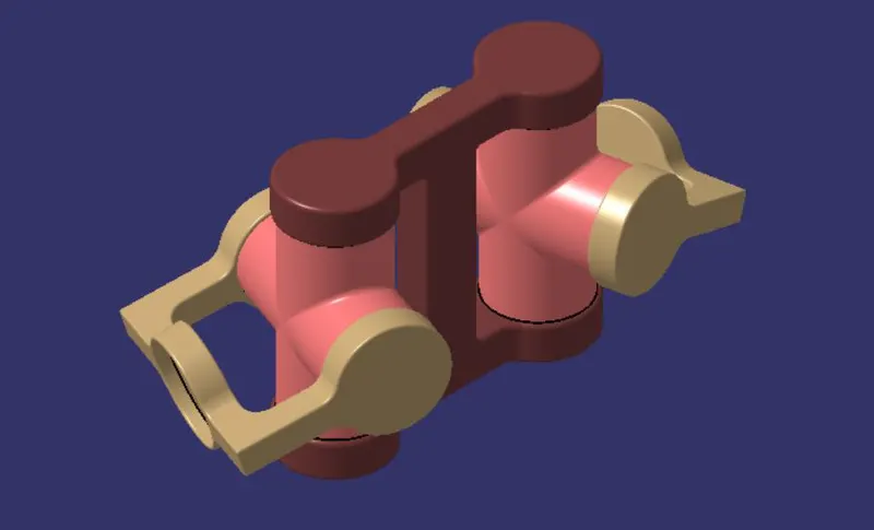
After giving all the constraints we save the assembly using save management with the help of which we can save all the modified components too.
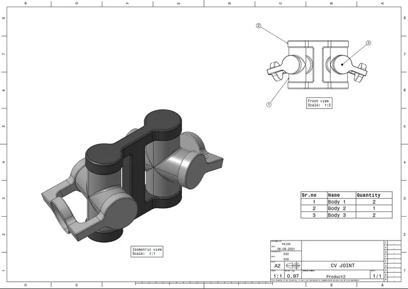
Then we open the drawing workbench to make a 2D drawing of the CV joint assembly and its components.
CONCLUSION
From this project we got to learn about assembly and all the tools used for assembly modelling.