Advanced Sheet Metal Design Using NX Cad Challenge_2_Box Assembly
SHEET METAL BOX ASSEMBLY USING NX CAD
INTRODUCTION
This project is mainly to understand the different tools and features used in NX cad software for modelling a sheet metal box assembly and to get a clear knowledge and understanding of the features and tools in NX cad.
OBJECTIVE
The main purpose and objective is to understand and learn all the features and tools used in the NX cad software.
METHODOLOGY
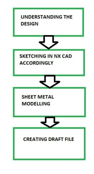
The first step is to understand the design of the casing which we are going to model.
After that we will sketch the model or the part in the NX cad software.
Then using the appropriate feature and tool from the sheet metal we model the part.
After completing we will draft the model.
DESCRIPTION
Box Assembly-
- MODELLING
Tools/Features used-
- Sketch
- Tab
- Flange
- Closed corner
- Hem flange
- Mirro body
- Unite
- Dimple
- Unbend
- Re bend
- Break corner
- Normal cut out
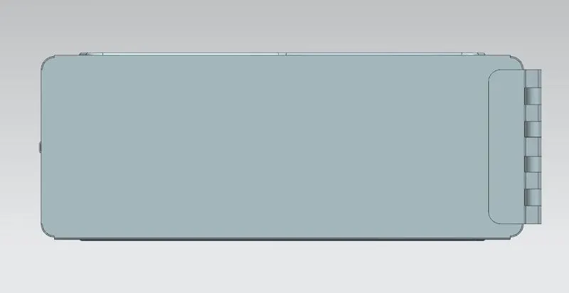
In the first step we first sketch the base of the box assembly. Then using that sketch we create a tab. The tab feature allows us to extend a sketch according to the thickness value given in the preferences. Then we use the flange tool at the corner. We use closed corner to tool to close the corner of the two adjacent flanges
Hem flange is used the fold the flanges onto itself.
What we created till now was half body, now to complete the body we will mirror the body. What we get is two solid body, so now to combine the two solid bodies we use the unite feature which is used for combining. Then we use the dimple feature to lift an area on the flange. Then we will mirror that too. Then we will unbend the sheet metal and again rebend it.
Then using the bead feature we again lift a particular area along the sketch contour to resemble a small leg of the box assembly. Then again using the mirror feature we mirror this on all the four corners.
The cut out feature is used to cut or remove some material by projecting the sketch onto a model.
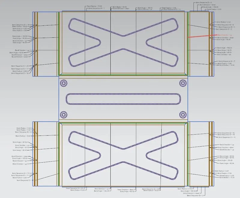
After using all these features and tools we create a box assembly and then we create a flat pattern for understanding it in two dimension and to show the sheet metal without any bends.
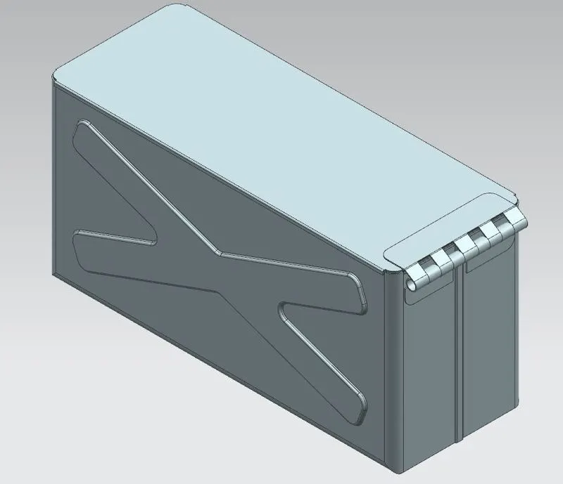
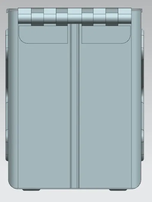
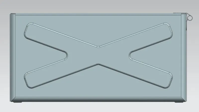
- DRAFTING
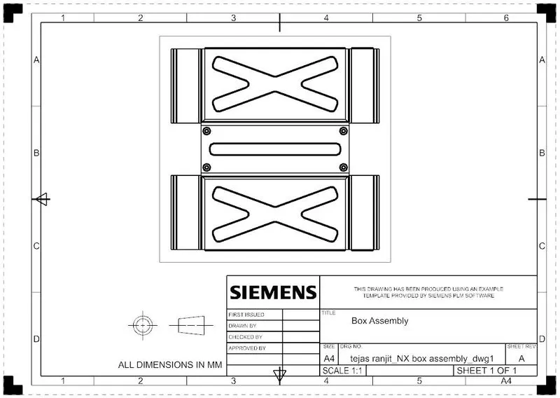
The draft is nothing but a two dimensional (2D) drawing of the model which we created for better understanding of the model.
CONCLUSION
We were able to model the Box assembly with sheet metal and got to learn about the various features and tools used in NX cad for sheet metal modelling.