Assembly of Yacht
MODELLING AND RENDERING OF A YACHT
INTRODUCTION
The purpose of this project is to understand all the tools and features used for modelling a product like the Sunseeker Predator Yacht and its parts to get a clear knowledge about the tools and features used in Solidworks.
OBJECTIVE
The main objective of this is to learn and understand the tools used in solidworks for part modelling, specially surface modelling and to assemble all the parts modelled and to render the model to give it a realistic look using solidworks visuals.
METHODOLOGY
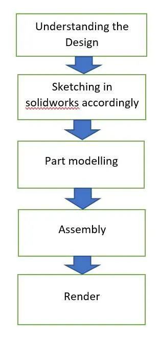
The first step is to understand the design of the model we are going to create.
Then we sketch the model on plane in solidworks accordingly. We sketch all the main parts using the sketch or the blueprint of the model.
All the parts are modelled according to the design and blueprint.
After modelling all the parts, all the parts are then assembled properly and accordingly.
Then the final step is to render the yacht to give it a realistic and appealing look.
DESCRIPTION
A.PART MODELLING
Before modelling a few parts we needed a proper sketch or blueprint of the model. So we first took the blueprints of all the views of the model and placed it according to the dimension.
This would act as reference for most of the parts of our model.
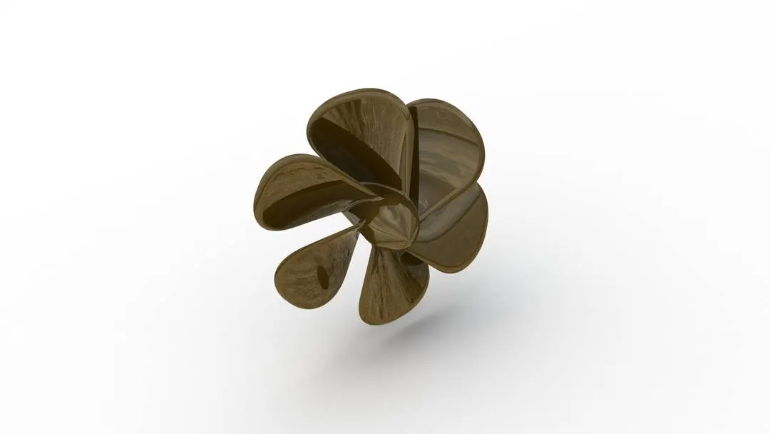
1.Propeller
A propeller is a device used to transform rotational power into linear thrust.
Features/Tools used -
- Sketch
- Revolve
- Loft
- Fillet
- Cut Extrude
- Circular pattern
The first thing we did was sketch the rotating hub of the propeller and then with the help of the revolve we made the hub.
Then with the help of a reference plane and loft we made the blades of the propeller. Fillet was used to give a rounded edge to the blade.
With the help of cut extrude a space created in the hub for the shaft.
Circular pattern was then used to pattern the blades around the hub evenly.
2.Radar
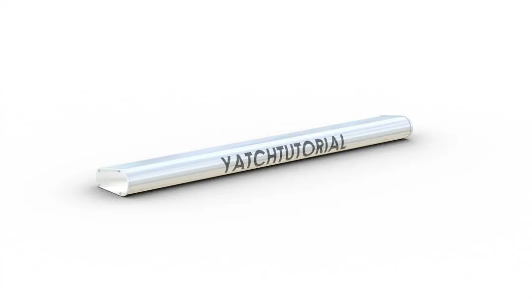
Radar acts as a major navigation aid for boaters.
Features/Tools used -
- Sketch
- Boss Extrude
- Cut Extrude
- Fillet
- Sketch pattern
- Mirror
- Split line
Modelling Radar is quite simple. With the help of boss extrude and with fillets we create the structure of the radar, then we go on to add some details to the radar using sketch pattern, fillet and even using split line for encrypting the name on the radar face. Then we gave the appropriate appearance.
3.Hull
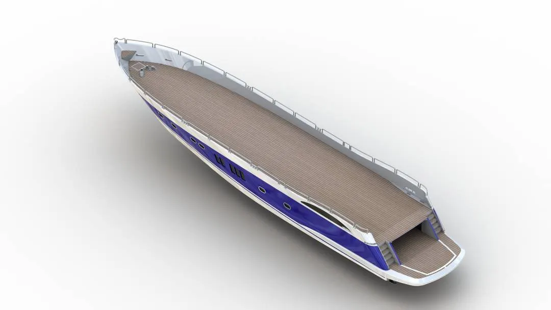
Hull is the watertight body of the boat or a ship.
Features/Tools used -
- Sketch
- Projected curve
- Surface loft
- Surface trim
- Surface knit
- Surface fill
- Extrude boss
- Extrude cut
- Fillet
- Chamfer
- Sweep
- Delete face
- Revolve
- Pattern
- Split line
- Mirror
For making the body of a hull we mainly used the projected curve to get the proper shape of the hull. Surface loft feature is used after this. This feature allows to make surface between two or more profile.
Then using all the above mentioned features and tools we modelled the hull accordingly.
For making the garage space in the hull we first make a small cut around the space of the garage, then when we cut extrude the remaining body it becomes the two different solid bodies. The second solid body which was produced because of the cut, we save it so as to make the garage door.
We also model the shaft where the propeller will be fixed.
The delete face is used to delete the unwanted face in the body, it patches or fills the face with the remaining.
We even model the railings. Here also we will first project the path on the railing and then will use the sweep feature.
When we mirror the body we will try to make it a solid body. If the body does not form a solid body then that means there is a leak in the surface which should be fixed. After fixing this we can move on to giving an appearance to the hull.
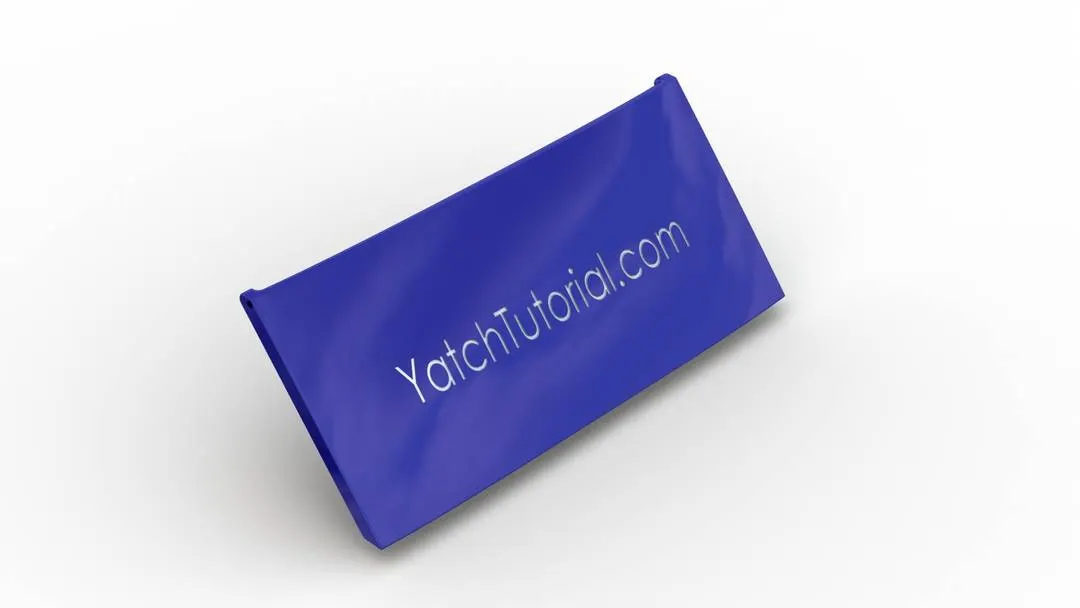
4.Garage Door
It is used to close the garage
Features/Tools used -
- Extrude cut
- Shell
- Fillet
- Mirror
The solid body which we saved before when we cut from the hull is used to make the garage door. We use the shell feature to make it thin. Shell helps in making thin wall feature in the model,
Then we will mirror it and give appropriate appearance.
5.Front Seat
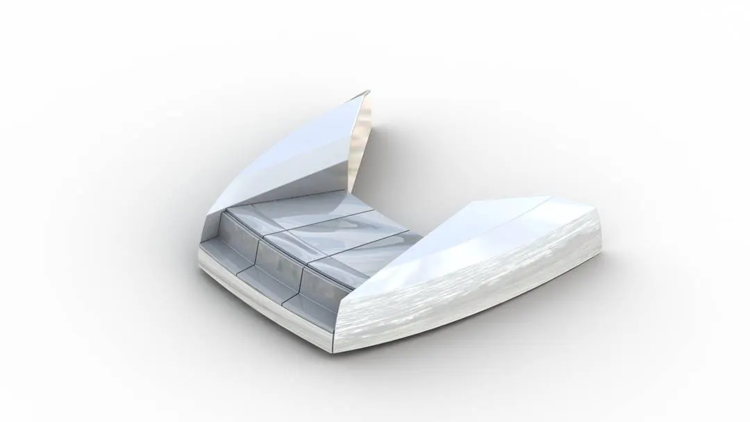
Simply used for a comfortable seating of the people in the front.
Features/Tools used -
- Sketch
- Surface sweep
- Surface Extrude
- Surface trim
- Surface fill
- Surface knit
- Surface loft
- Extrude cut
- Revolve
- Fillet
- Chamfer
- Mirror
- Dome
First we will insert the hull model but we select only the surface and then we will use it as a reference to model all the other parts. We will repeat this step in all the other parts also which we are going to model.
Using all these features and tools we model the front seat of the yacht according to the blueprint.
Surface sweep is used first, it is the same as that of a normal sweep feature, it makes a swept surface along the selected sketch. Then we used other surface options and then revolve tool for modelling the seat.
We use the dome feature also in the back bed for the people to rest. Then we will give the appearance accordingly.
6.Middle seat
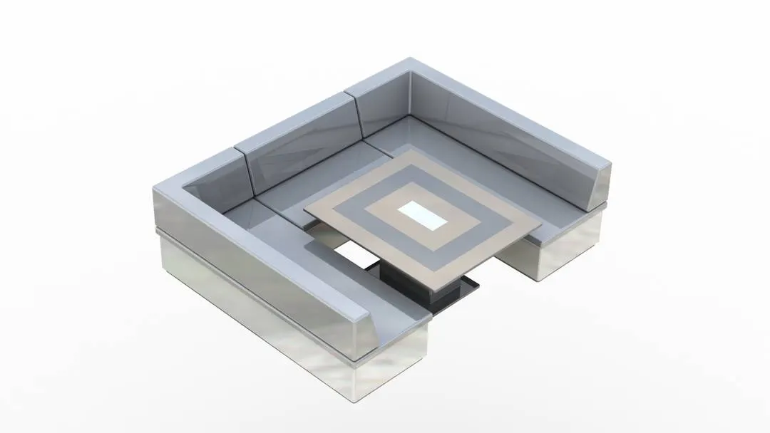
Middle seat is designed for the people to sit comfortably in the middle with some nice dining table for the passengers.
Features/Tools used -
- Sketch
- Extrude boss
- Fillet
- Chamfer
- Mirror
The modelling of the middle seat is quite simple using the basic features of the solidworks to create a nice looking rear seat according to the design.
Sketch the surface and then extrude it and then use all the above feature.
Also gave appropriate appearance accordingly.
7.Rear seat
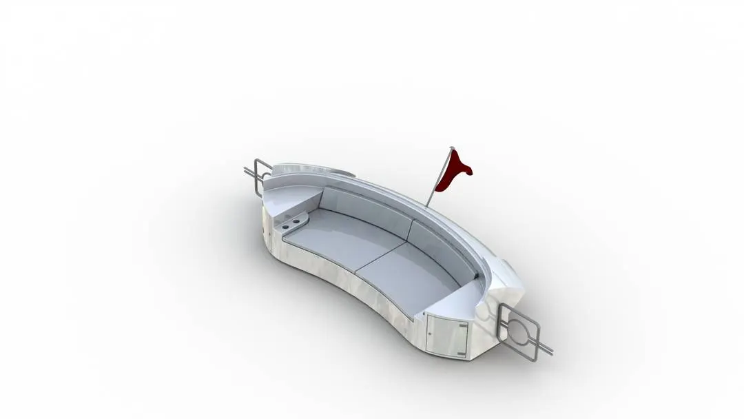
Rear seats are used to the people in the back to rest.
Features/Tools used -
- Sketch
- Surface sweep
- Surface trim
- Surface sweep
- Ruled surface
- Surface extend
- Surface extrude
- Surface loft
- Extrude cut
- Extrude boss
- Chamfer
- Surface offset
- Fillet
- Revolve
- Mirror
According to the blueprint we model the rear seat with all the tools and features mentioned above. We use extend surface option to extend the side of the surface even more accordingly and then there surface offset option which create an offset surface accordingly. Then using mirror option we mirror and create a solid body. With the help of 3D sketch and surface loft we even create a flag for our yacht.
After completing all these things we give appropriate appearance.
8.Superstructure
A superstructure is an extended construction of the upper body of the yacht.
Features/Tools used -
- Sketch
- Surface sweep
- Surface Extrude
- Surface trim
- Surface fill
- Surface knit
- Surface loft
- Extrude cut
- Revolve
- Fillet
- Chamfer
- Mirror
- Dome
- Extrude thin
- 3D sketch
- Projected curve
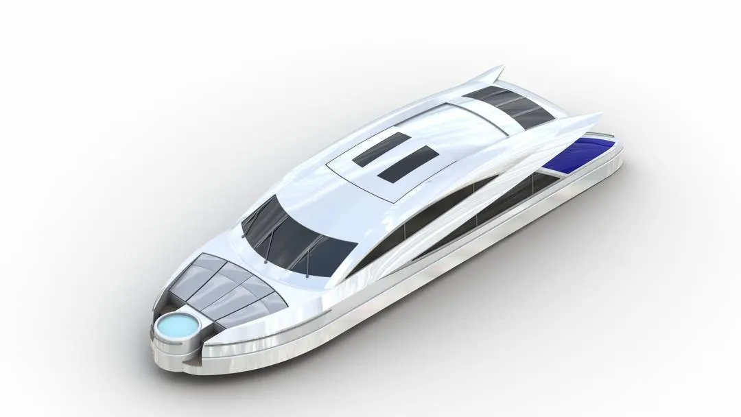
By this time we are quite familiar with all the tools and features. So by using all the above mentioned features and tools we model the super structure of the yacht.
Using projected curve and lofted surface option we model the surfaces of the superstructure.
We even model the jacuzzi in front of the structure and then using sketch we gave path of the railings which are to be made using sweep feature.
In this we also model the wipers for the windshield.
While modelling this we are going to use the offset surface for the top portion where the radarmast will be located. Then we will hide the surface that we just offset.
Then we will give the appearance accordingly.
9.Radarmast
Radarmast are basically mount which is located on the top.
Features/Tools used -
- Sketch
- Extrude boss
- Revolve
- Sweep
- Projected curve
- Fillet
- chamfer
- Shell
- Dome
- Mirror
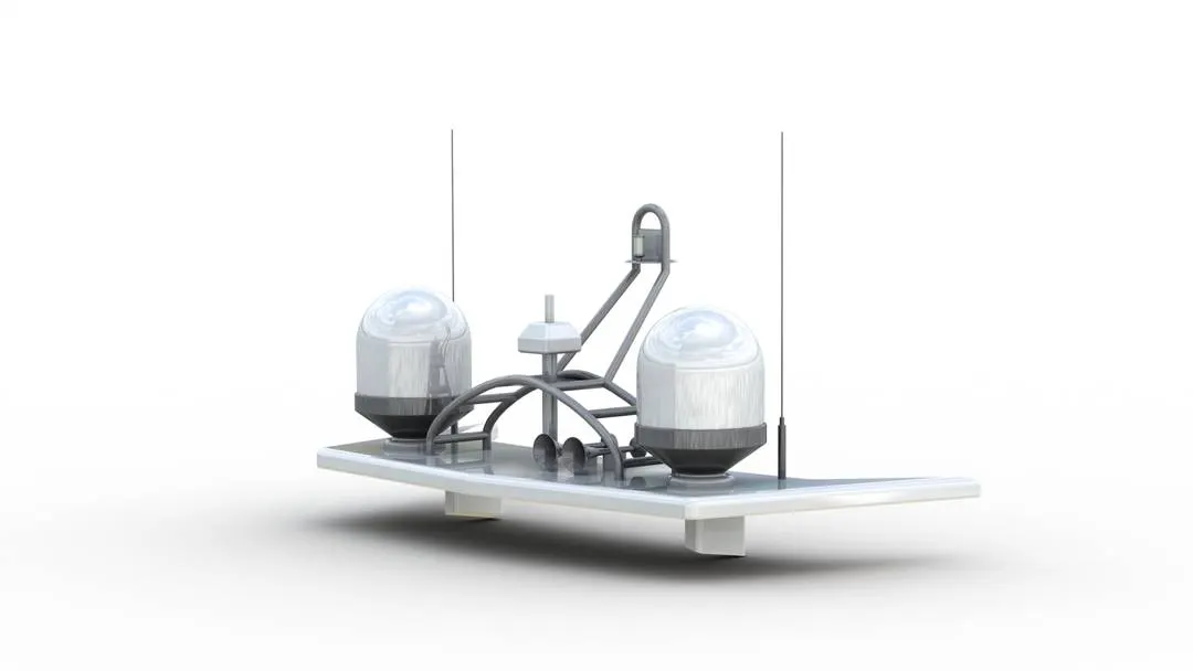
Here we will insert the surface of the superstructure and use the radar mast reference which we had offset the surface and saved it for modelling the Radarmast.
Using all these features and tools we model the radarmast. We model a double horn too on the right side of the radarmast. The shell feature was used to make the surface of the horn thin.
Then the last step is to give the appropriate appearance.
B.ASSEMBLY
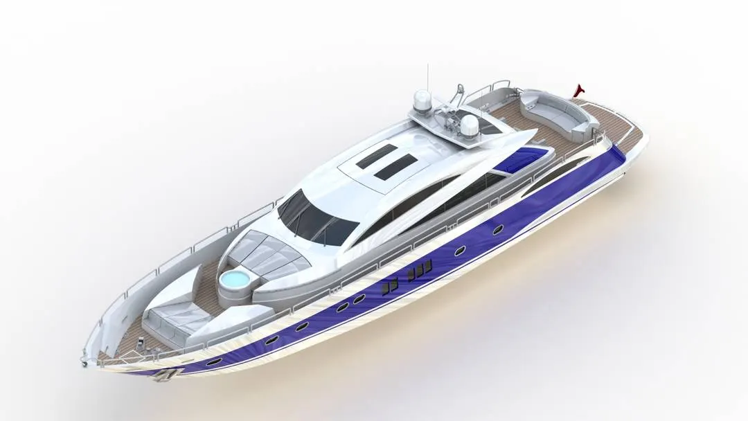
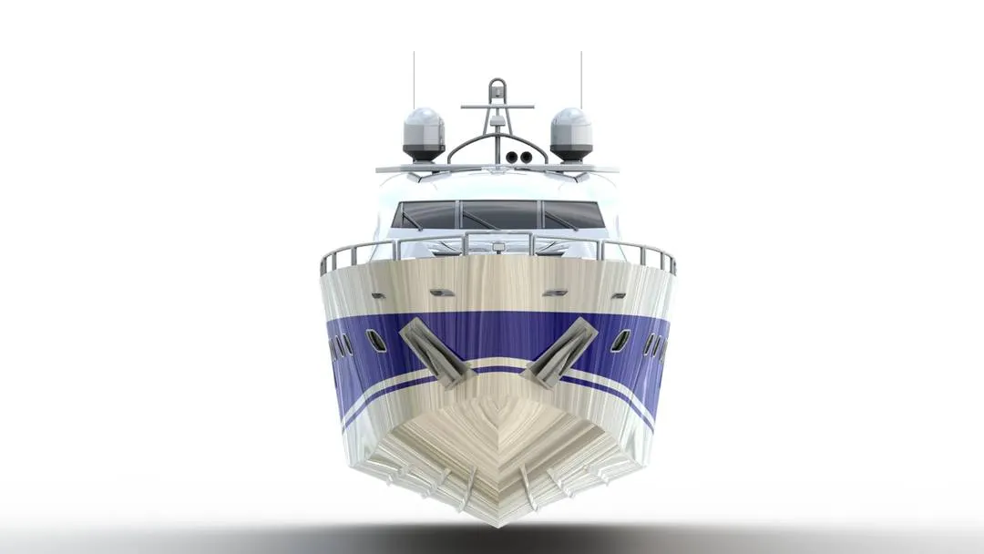
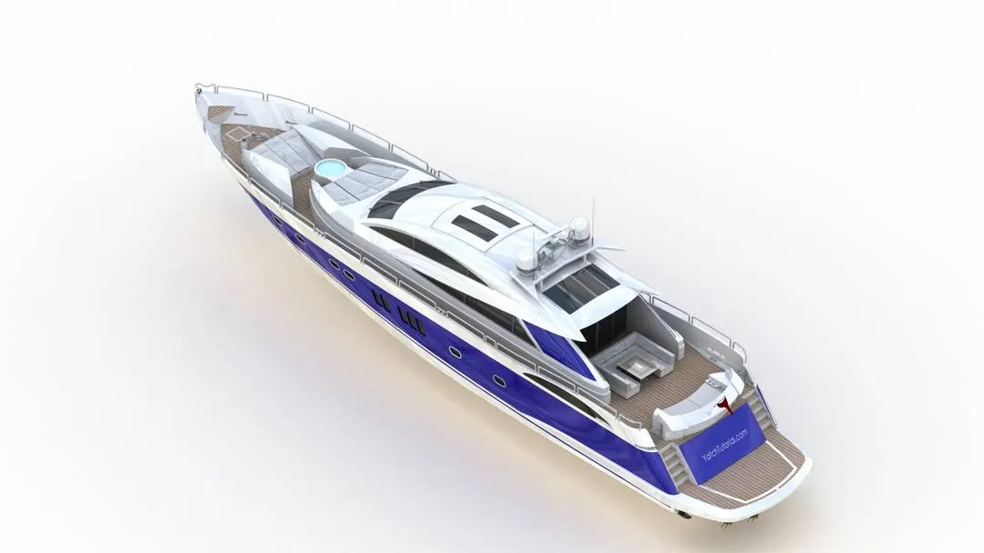
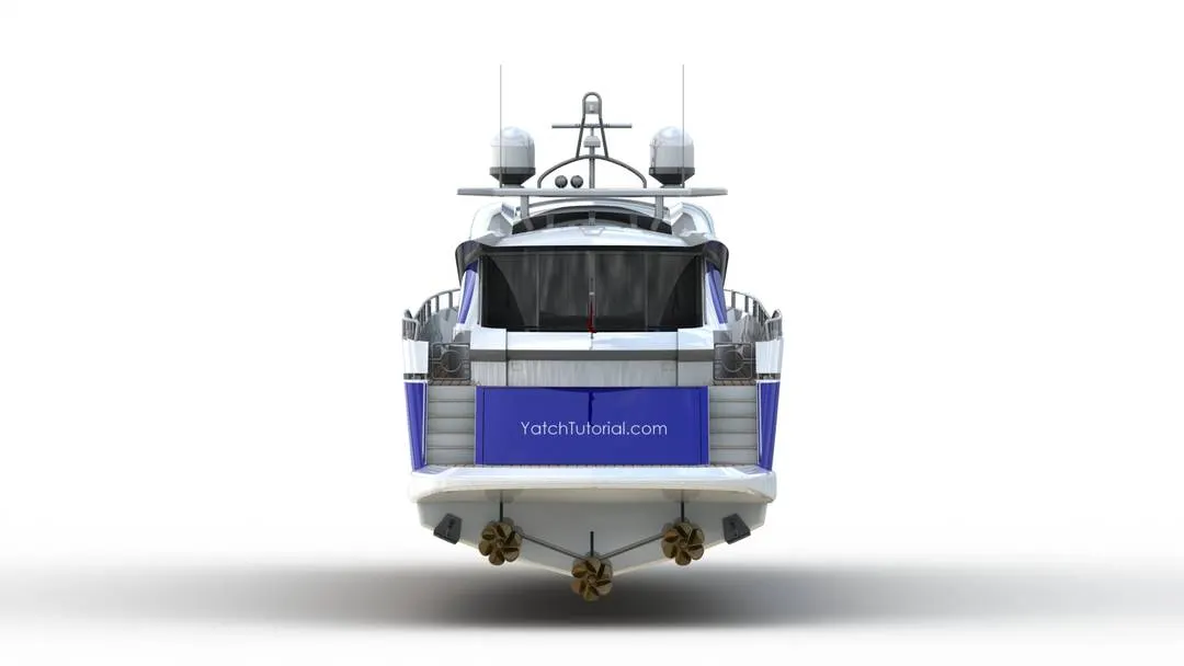
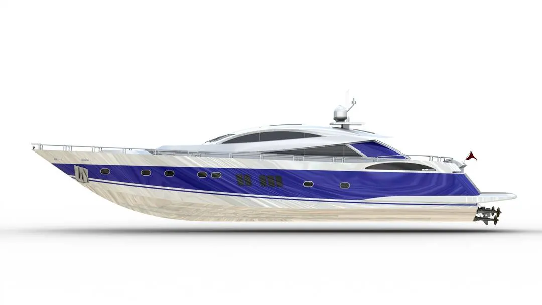
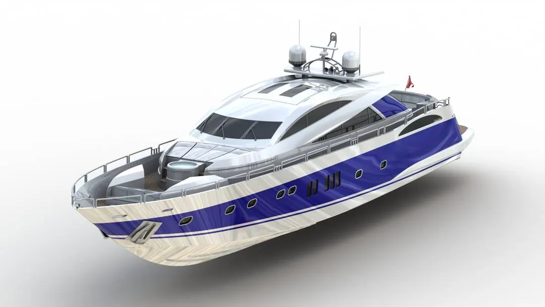
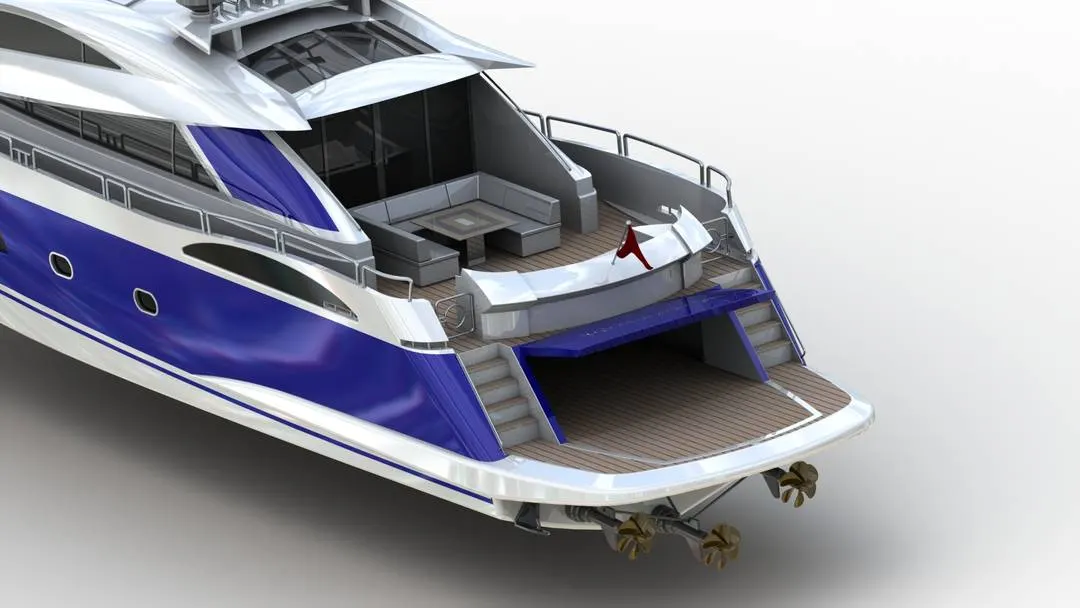
In this step we are going to assemble and mate all the parts that we modelled of the sunseeker predator yacht.
We first insert the hull and fix it then we insert and fix all the other parts with the hull accordingly.
We give mates to some of the parts like the propeller, radar and the garage door and even the rear seats.
C.RENDERING
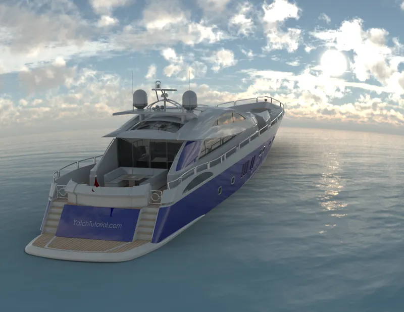
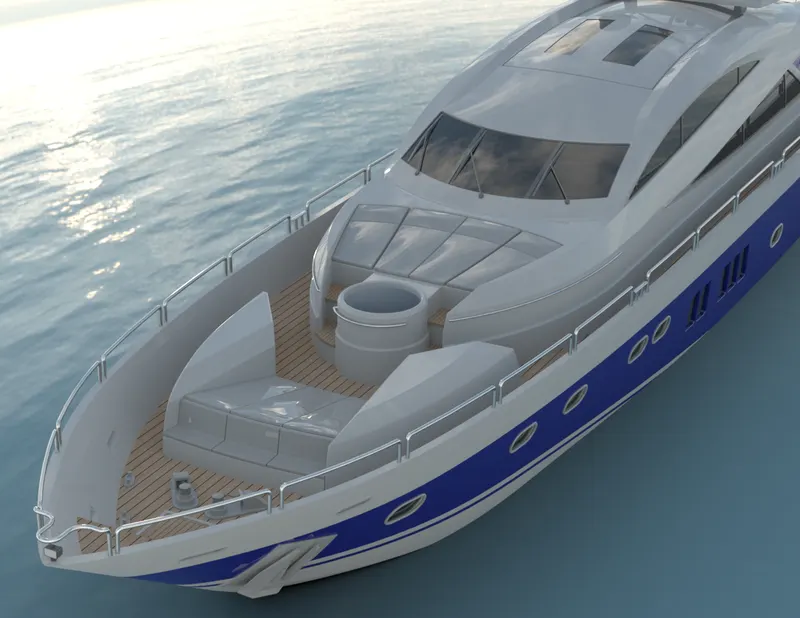
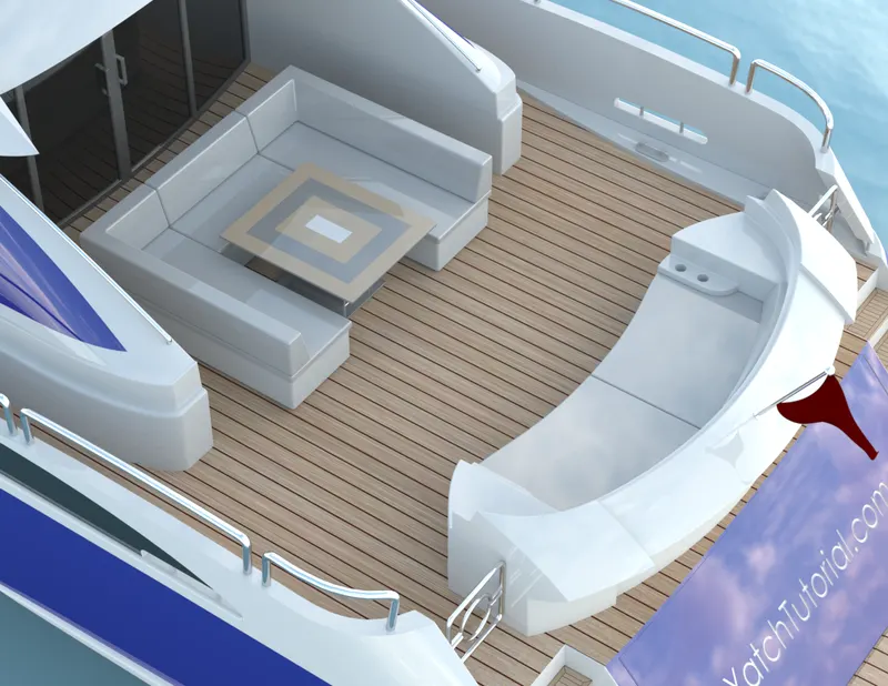
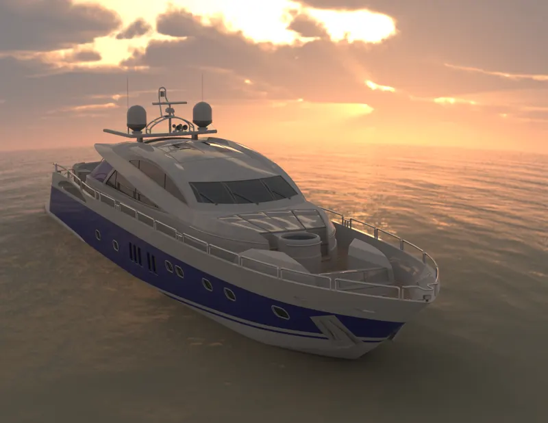
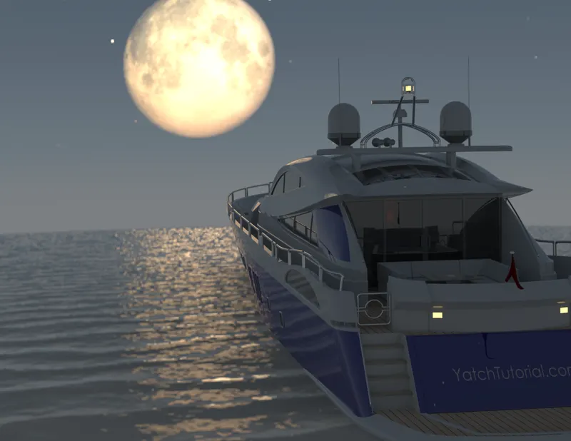
Render means we will be creating a high quality image of the model or giving it a realistic look to the model in order to present it in a nice and presentable way,
Gave the appropriate colour and appearance to the yacht.
I placed the yacht in a HDR environment and scaled and placed it accordingly.
In solidworks there is a render tool with which we can render. There are many options there like we can add cameras, we can add lighting and create or place the model in many environments.
We can even render the model in solidworks visuals.
The yacht model was rendered in both the softwares.
CONCLUSION
We were able to model all the components of the sunseeker predator yacht and because of it we are now familiar with all the important features and tools and specially all the surface tools used in solidworks.
We were able to assemble all the components and mate it accordingly.
We were also able to render photo realistic images of the models, also learnt about all the options for making a good quality render which we can present.