Photo Realistic Rendering
Modelling and Rendering an American Chopper using Solidworks
INTRODUCTION
The main purpose of the project is to understand all the tools used for modelling a product like the American chopper and its parts to get a clear knowledge about the tools in Solidworks.
OBJECTIVE
The main objective of this is to learn and understand the tools used in solidworks for part modelling, to assemble all the parts modelled and to render the model to give it a realistic look using solidworks visuals.
METHODOLOGY
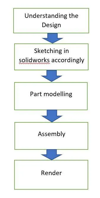
The first step is to understand the design of the model we are going to create.
Then we sketch the model on plane in solidworks accordingly. We sketch all the main parts used in an American chopper
All the parts in an American chopper are modelled according to the design.
After modelling all the parts, all the parts are then assembled properly and accordingly.
Then the final step is to render the chopper to give it a realistic and appealing look.
DESCRIPTION
A.PART MODELLING
1.Transmission Belt
A Transmission belt is used to transfer power from engine to the gear box.
Features/Tools used-
- Sketch
- Offset
- Extrude boss
- Fillet
- Appearance
The first step was to sketch the model on the front plane with all the dimensions and giving the relations and sketch constraints to get the sketch fully defined. After that we offset the sketch externally. Then we extrude that closed sketch according to the design to make it 3D and then with the help of fillet option we give to rounded edge to the edges of the belt.
The last step is to give appearance to the model as per the design. We gave matt rubber look to the belt.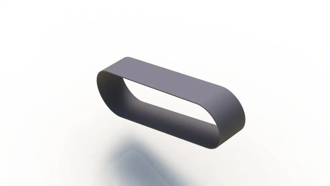
2.Kick Stand
Kick stand is used to support the vehicle from one side when the vehicle is not in use.
Features/Tools used-
- Sketch
- Loft
- Dome
- Split
- Extrude cut
- Extrude boss
- Fillet
The first step is we sketch an ellipse on the front plane, then we sketch a spile or a curve using the spline tool in sketch on the right plane which starts from the centre on the ellipse. We dimension it accordingly. From the end of the spline we make a reference plane so that we can sketch another ellipse which may be smaller than the previous one.
Using the loft feature which helps to make solid bodies in 3d using two sketches, we select the two sketches. It also asks for the direction in which the loft should move, we select the spline which we created.
The dome feature helps to create a nice dome structure on the top of both the ellipse.
Split feature allows us to split the model or a face with help of a reference sketch. Here we split a small portion from the model on the lower end of the stand and we remove that portion so that we get a flat face.
Using extrude cut we cut a portion on the upper end for the stand to mount on the chopper.
Then we sketch a small circle in the top plane in the area of the extrude cut so that we can use extrude boss a make a cylinder inside the cut part so as to provide a pivot for the kick stand.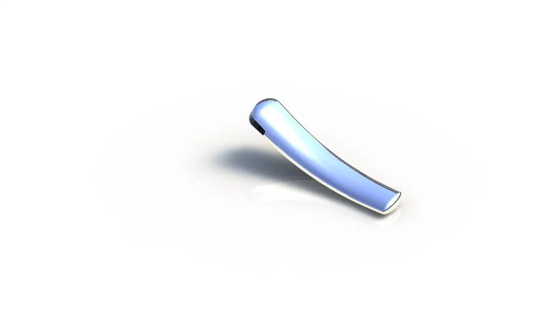
3.Front Fender
It is located with the front wheel and helps in preventing the dirt from flying outside when the wheel rotates.
Features/Tools used-
- Sketch
- Revolve
- Dynamic Mirror
- Split
- Trim
First we sketch on the vertical plane, then revolve tool is used. When using the revolve tool we select the sketch and the plane or the centre line along which we have to revolve.
Dynamic mirror allows us to preselect a plane or a line along which we want to mirror then when we sketch all the entities are mirrored on the other side. We use this sketch to split a portion from the revolved part.
Then we give fillet to all the edges and give the fender an appearance accordingly.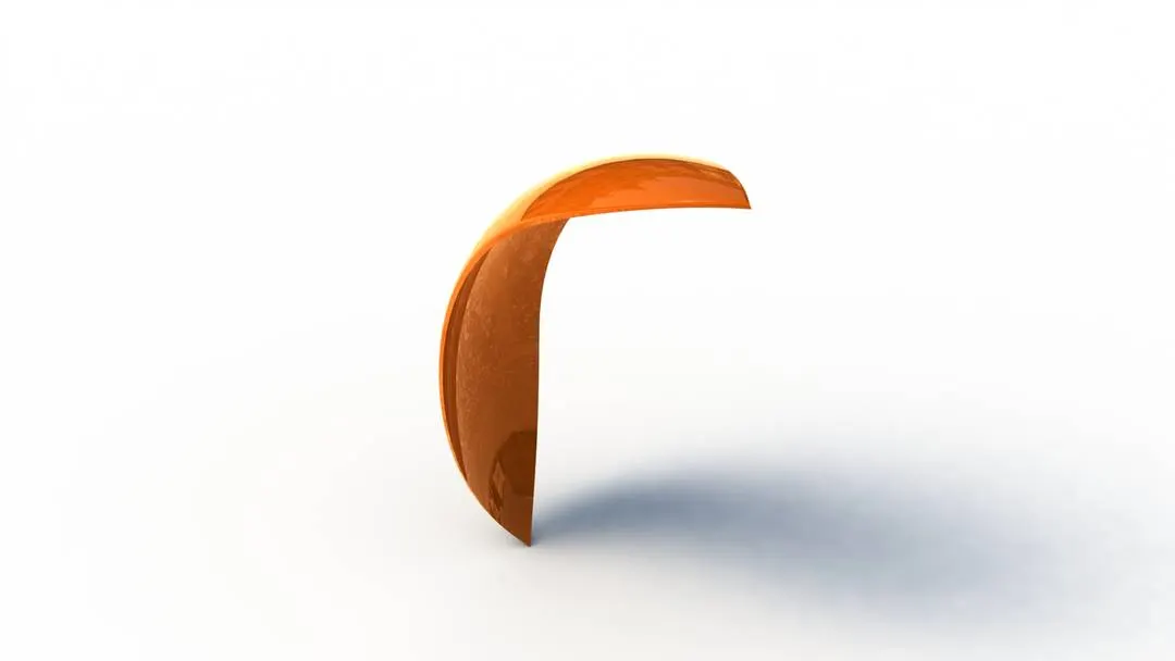
4.Rear Fender
The function of the rear fender is same as that of the front fender, the difference is it being in the rear.
Features/Tools used-
- Sketch
- Revolve
- Dynamic mirror
- Split
- Shell
The procedure which we used for building the front fender is the same procedure which we are going to use for making the rear fender.
The only difference here is that we used the shell feature in the rear fender. The shell feature helps in removing material from a solid body and to create a thin wall feature.
Then is give the rear fender an appropriate appearance.
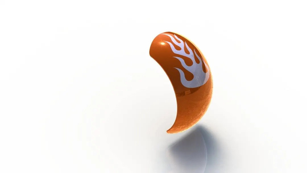
5.Oil Tank
Oil tank is used to store the oil in a vehicle
Features/Tools used-
- Sketch
- Extrude boss
- Combine
- Fillet
- Shell
Here we sketch on two planes. One on the top plane and on the mid plane. Then we extrude them both separately. We get two solid bodies.
To get our final result we have to combine the two solid bodies. The function of the combine feature is to combine two solid bodies and get new single body.
After this we need to add fillet to all the edges and then with the help of shell feature make this body hollow.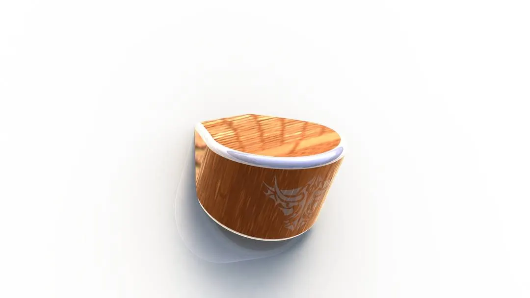
6.Chain
Chain is used to transfer power from the gear box to the rear wheel.
Features/Tools used-
- Sketch
- Sketch block
- Extrude boss
- Fillet
- Pattern
- Mirror
The first thing we do is create a path for the chain links by sketching in the mid plane.
Then on the same plane away from the path we created we sketch the chain links for the chain. Selecting the sketch of the chain link we made, we make it to a sketch block. The reason we made this into a block it that is it stored and saved so we can recall this sketch at any time and at n number on times as per the need.
We placed the sketch block accordingly on the patch and then extruded the link and the pin which join the two chain links and then we give fillet to the pin.
After that we use curve driven pattern to copy the chain licks according to the path. Pattern is a very helpful feature when we want to copy a feature according to specific pattern.
After completing the pattern and connecting the chain licks and pins we need to create this on the other side of the pins. To do this the use the mirror feature and mirror the pattern along the mid plane.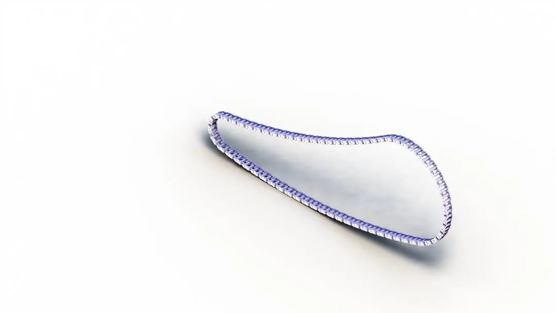
7.Pedal
Pedal is part on a bike used to place our foot over them while riding a bike.
Features/Tools used-
- Sketch
- Extrude boss
- Revolve
- Dome
- Chamfer
- Fillet
The first step we do is sketch the pedal on the front plane then we extrude it. After that we sketch the pins that will be attached to the chassis and will extrude it too.
Using the top plane we sketch and revolve to create a part to rest our foot on the pedal, similarly we sketch on the front plane and extrude the parts for foot rest.
We create a dome structure on the end of the foot rest on the pedal.
Using chamfer feature we give a pointy taper on the edges of the foot rest. Chamfers are used to give tapers after modelling the part.
With the offset feature and then mirror feature we were able to make pattern on the foot rest.
Fillet was given to all the edges of the pedal to avoid any pointy edge.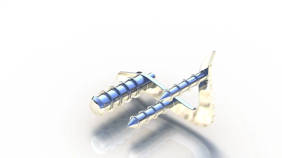
8.Front Wheel
Wheel is part which revolves on an axle and helps in giving motion to the vehicle. Front wheels are also used to steer the vehicle.
Features/Tools used-
- Sketch
- Revolve boss
- Extrude boss
- Extrude cut
- Revolve cut
- Combine
- Pattern
- Fillet
- Chamfer
On the front plane we made the sketch and used the revolve feature to make the outer rig of the rim. Then for the spokes created the sketch on right plane and extruded it. Then with the help of reference geometry make a design on the body, here we are making a spider web design and then extrude cut it so as to get the spider web design. Then from the front plane use sketch and revolve cut to get a even better design
Then using the circular pattern copy the pattern to get a nice design on the rim of the wheel.
Then using the combine feature combine all the all the bodies which we made to one body to get a nice rim of the wheel
After this we make the brake rotor and the brake calliper. For the brake rotor we extrude a circle a little offset from the rim and then making pattern on the rotor. Then we move on to the calliper. We simply make the sketch on the rotor then extrude it both way. Then chamfer the calliper on both the side.
Using convert entities we convert the reference from the curve and making the sketch to make the tyre with revolve feature around the rim. Then design the thread pattern and then extrude cut it. Select this feature for making circular pattern around the tyre.
With the help of extrude cut we make the hole along the wheel and the rotor for the axle to pass between them.
Then we give appropriate appearance to the wheel accordingly.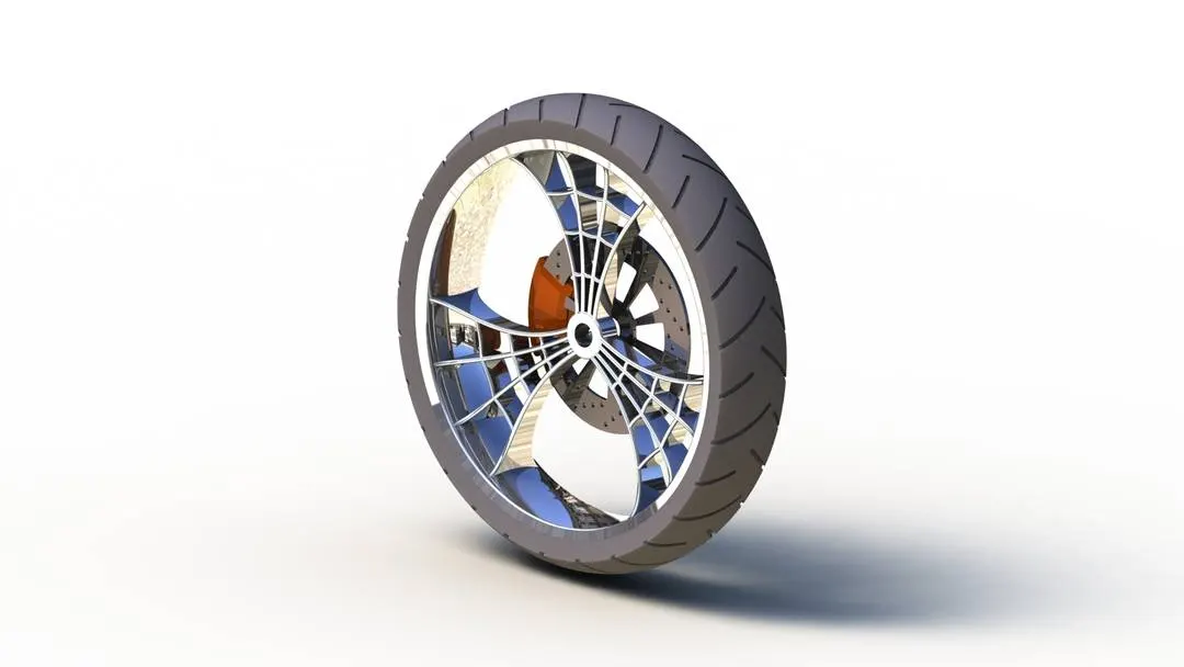
9.Rear Wheel
Rear wheel is the wheel where the power is transferred from the gear box.
Features/Tools used-
- Sketch
- Revolve boss
- Extrude boss
- Extrude cut
- Revolve cut
- Combine
- Pattern
- Fillet
- Chamfer
The procedure we use for making the rear wheel is exactly the same as that of the front wheel.
The only component added extra to this is the sprocket to which the chain will be attached.
The sprocket is made my taking into reference the rotor of the wheel. The slots were made using circular pattern and extrude cut. After the sprocket was made, some materials were removed using extrude cut and circular pattern and then fillet was given inside the gap of the slots.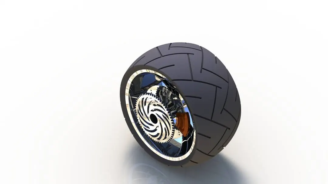
10.Front Fork
The front fork is basically used to hold the front wheel and guide and steer the vehicle.
Features/Tools used-
- Sketch
- Extrude boss
- Extrude cut
- Revolve
- Split
- Dome
- Project curve
- Sweep
- Mirror
- Combine
We will design and model the half portion of the model then we will mirror it across the plane to get a complete model,
In the front plane we make the sketch of the forks so that we can make a revolve and model it. Then on the end of the fork ,which is the flat end of the fork, we model the half of the triple clamp. We then use the linear pattern to model a triple clamp below a few distance of the original triple clamp. We also extrude a third cylinder to connect both the triple clamp
The main challenge was the understand and make the handle using projected curve. It is nothing but a curve we draw in 3d. For using projected curve we must draw 2 sketches on any two plane then we get a 3d curve between those two plane. The end point and start point must be the same when we sketch the curve on two planes. Then we can give this for direction during sweep. Using this method we make the handle and the brake line of the front fork.
After this we make the grip and the brake for the handle using simple revolve and cut extrude. We even make the headlights with the help of revolve cut and extrude cut and use the dome feature.
Then we mirrored the body and with the help of combine feature we made a single body.
Now for the appearance we give the entire front fork chrome finish. For the grip we use the rubber material. For the headlight, the lens if the headlight is given the appearance of white area light.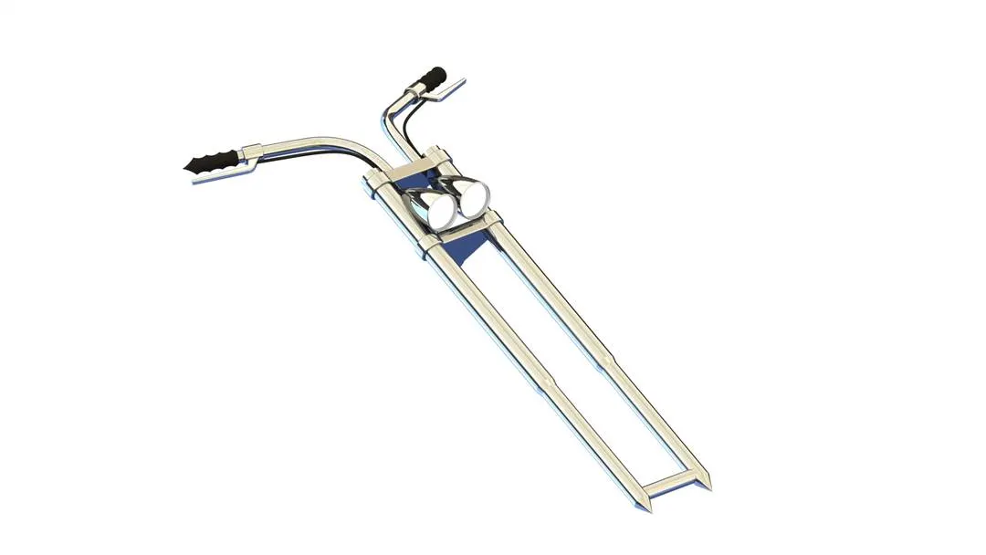
11.Chassis
Chassis is the main framework or the structure which carries all the load of the vehicle and where all the parts on the vehicle fit in.
Features/Tools used-
- Sketch
- Extrude cut
- Extrude boss
- Sweep
- Fillet
- Revolve
- Dome
- Project curve
- Combine
- Fillet
So here the first step we do is import the blueprint or the design sketch to the plane so that with the reference of this we could built the chassis.
We make a sketch at the mid plane for sweep and then made sketch on two plane for project curve and then used it as the direction for the sweep of the sketch in the mid plane and then mirrored it along the mid plane.
Then by using all the features we know we just made the rest of the chassis and then we gave the appearance on the chassis accordingly.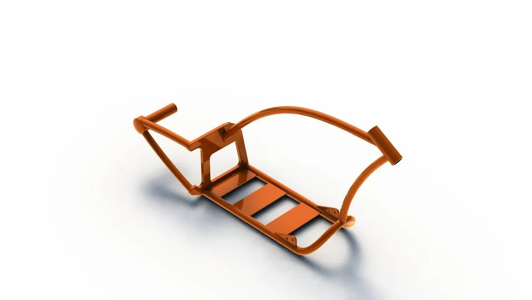
12.Engine
It is the main source of power to move the vehicle. It converts chemical energy to mechanical energy and this energy is transferred to the rear wheel.
Features/Tools used-
- Sketch
- Extrude boss
- Extrude cut
- Sweep
- Pattern
- Dome
- Split
- Revolve
- Mirror
- Projected curve
- Chamfer
- Fillet
We first import the blueprint or the design sketch into the plane.
Then we first start modelling the gearbox. Then gradually we start modelling the entire components using all the features we know. We model the pulley, the starter motor the cable the v type engine above the gear box its fins and all other components. We even modelled the air filter used in the vehicle.
We model the legs of the gear box on which it will rest and then finally with the help of projected curves and sweep we make the dual exhaust of the vehicle.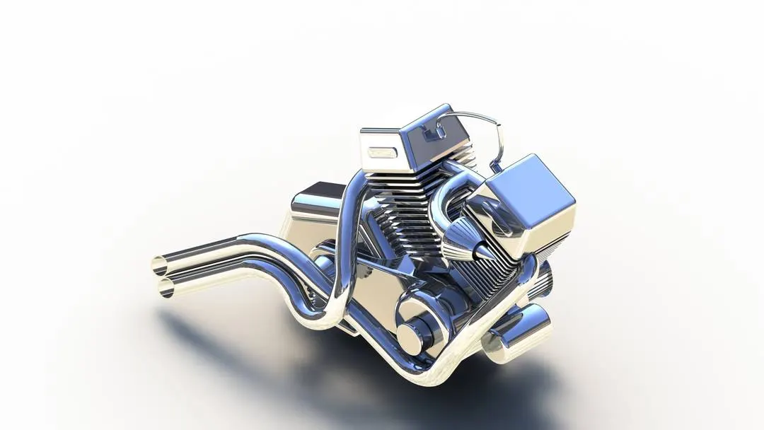
13.Gas Tank
The Gas tank’s main purpose is to store the gas used for running the engine.
Features/Tools used-
- Sketch
- Surface sweep
- Surface trim
- Projected curve
- Surface loft
- Boundary surface
- Surface knit
- Surface extrude
- Split line
- Fillet
- Cut sweep
- Mirror
- Shell
Here also the first step is to insert the blueprint so as to get a clear idea about what we are modelling.
We create a reference plane to make a sketch on it. After sketching on the second plane which will used as a path we use the surface sweep option. The surface sweep is same as the normal sweep, the only difference is that it sweeps the surface.
After that we make the sketch on the bottom plane according to the design and then will use the surface trim option to trim away the remaining surface.
Then make a projected curve and a sketch and with the help of these two sketch make a surface loft. The surface lost is same as that of normal loft with the only difference that it lofts the surface
Then again making a projected curve and sketch we use boundary surface. The boundary surface feature creates boundary surface between two profile in two different direction.
Then we mirror the entities on the other side of the plane and the use surface knit to join the two bodies into one.
For the seat we sketch it on the bottom plane and then using split line we project it on the gas tank model body which we created. Then we use surface extrude to extrude the surface up and the fillet it to make sure there are no pointy edges.
Then we cut sweep through the tank so as to provide a place the gas tank on the chassis.
Then the last step is to fillet all the edges and then with the help of shell feature make the gas tank hollow.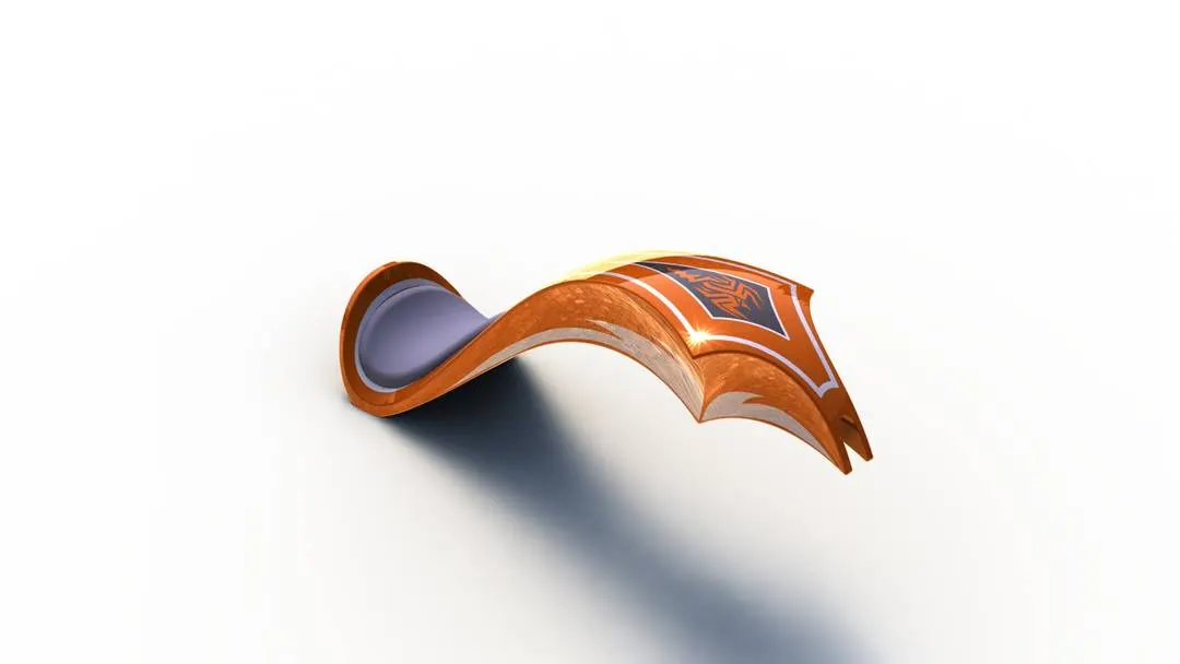
B.ASSEMBLY
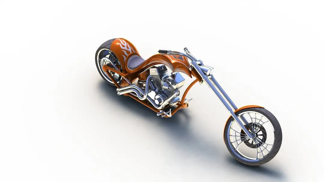
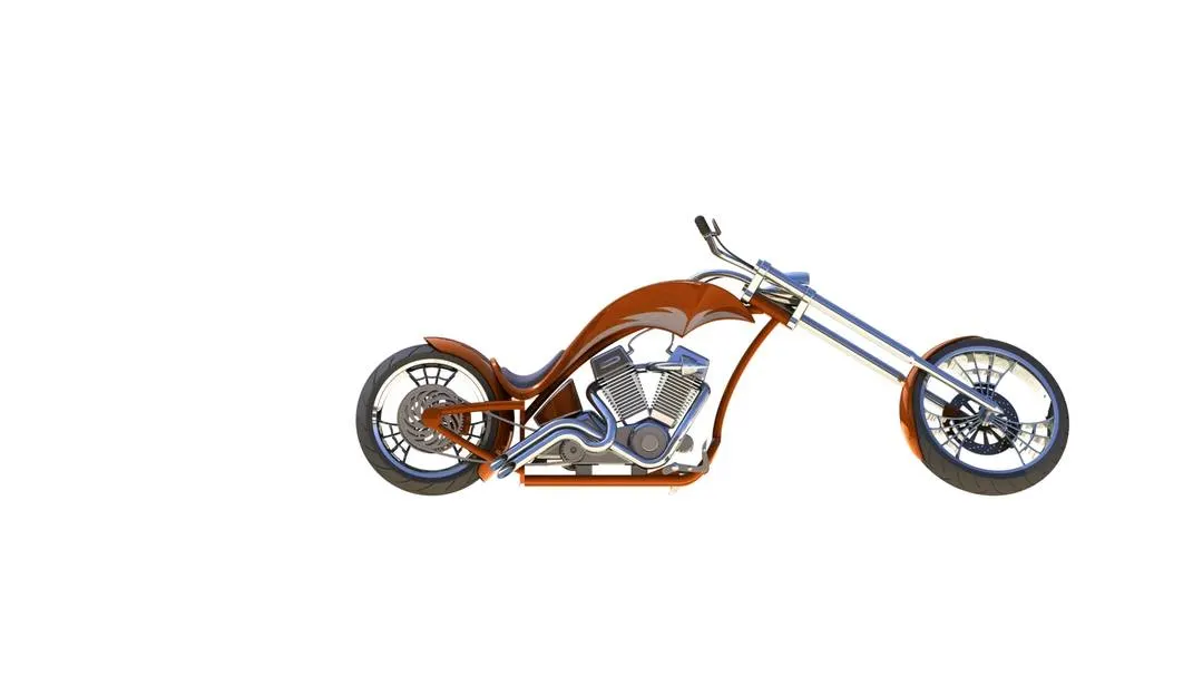
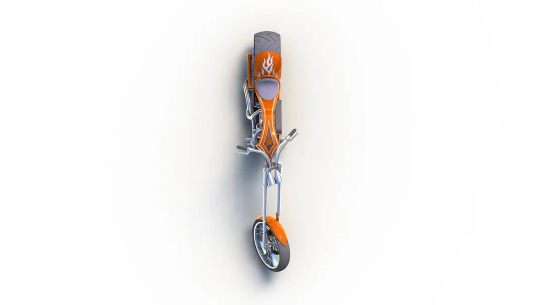
In this step we assemble all the parts which we modelled accordingly.
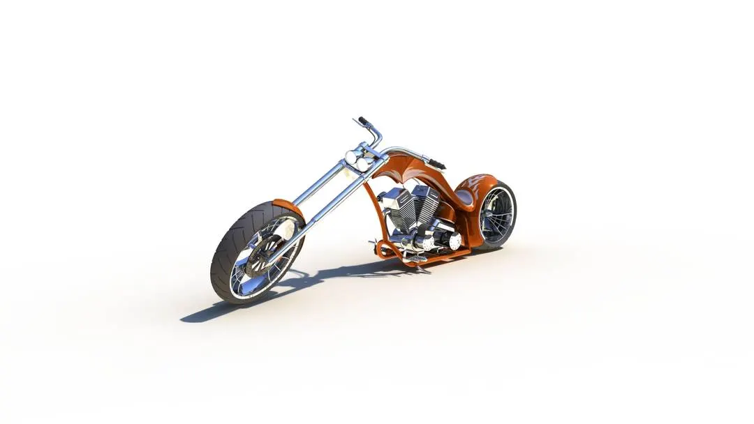
The first thing we do is with the help of insert component we will first insert the chassis which will be used as a reference to mate all the other model. Mate gives a geometric relation with respect to other components.
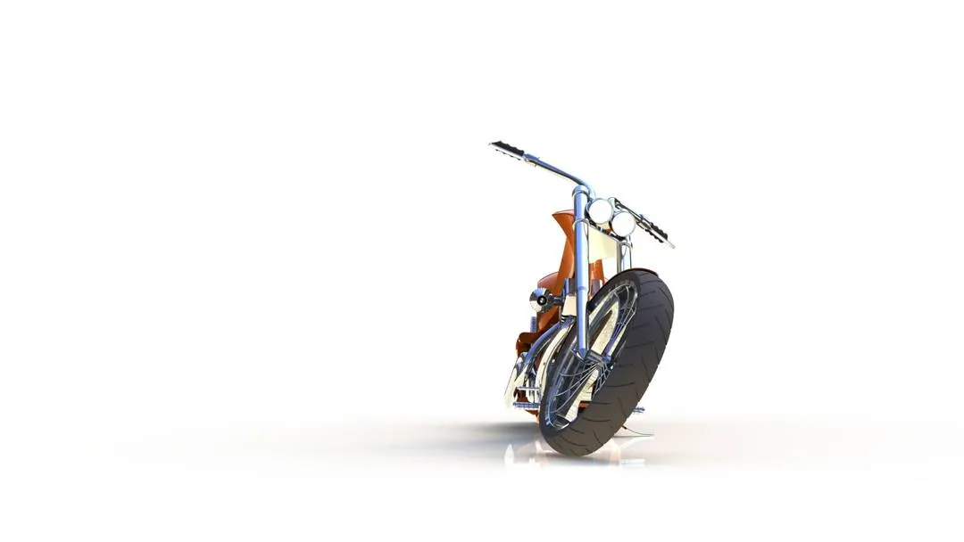
Then we step by step bring all the components and mate it which each other or we mainly mate it with the chassis so that when we move the chassis all the other components will also move along with the chassis.
C.RENDERING
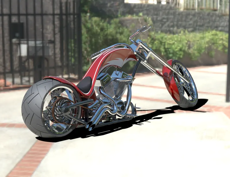
Render means we will be creating a high quality image of the model or giving it a realistic look to the model in order to present it in a nice way.
We first added decals to the components of the chopper to give a nice look.
In solidworks there is render tool with which we can render. There are many option there like we can add camera, we can add lightings and create or place the model in many environments.
We can even render the model in solidworks visuals.
CONCLUSION
We were able to model all the components of the American Chopper and because of it we are now familiar with all the important features and tools used in solidworks.
We were able to assemble all the components and mate it accordingly.
We were also able to render photo realistic images of the models also learnt about all the options for making a good quality render which we can present