Week 11- Assembly Workbench
.1 . QUICK RETURN MECHANISM
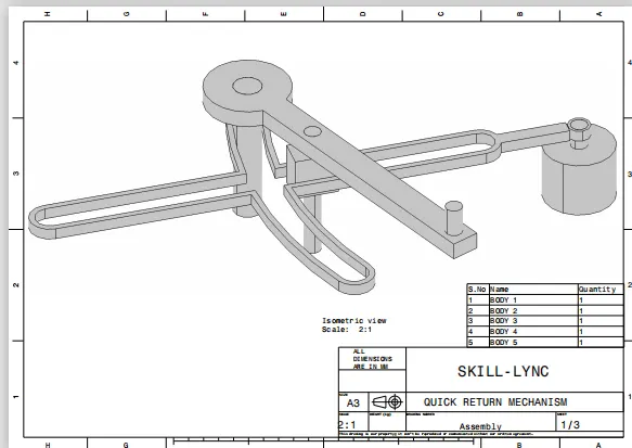
- complete the overview of the quick return mechanism.
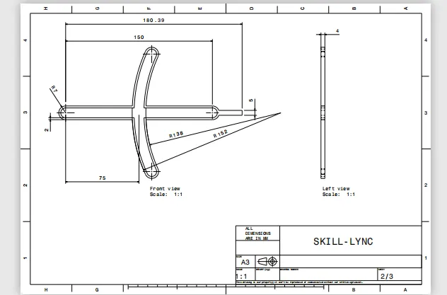
- take the draft sheet complete the overview of the 2d drafting,
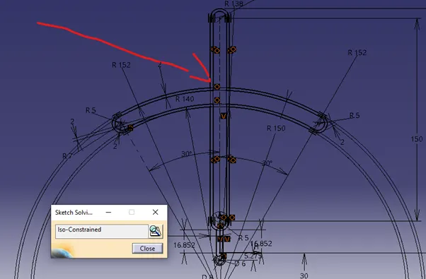
- Make sure line are in the iso constraint.
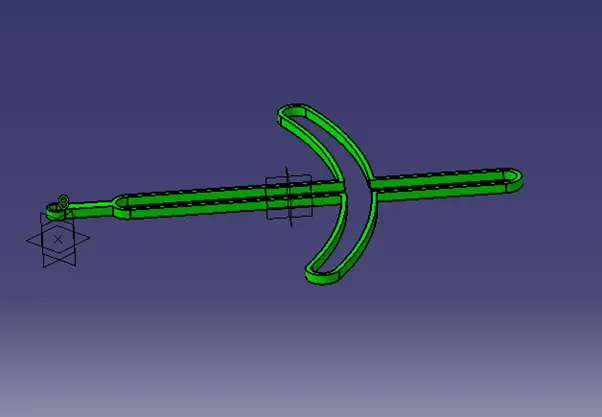
- After completing the draft go to the part design and pad at the length 4mm in the neutral.
-
Make sure every part body is support
- The same operation goes on other parts body.
- In a similar way other parts body as to do.
-
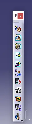
Assemble design.
-
Used to add the other body’s
Copy and paste special
Paste with as result link
It creates a tree structure 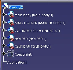
- Name the name by the requirement.
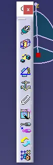
- constraint is connecting the two body by using the update.
- Select the Contact opposite sides of the part body surface.
- Fix command used to fix the part body at a required position
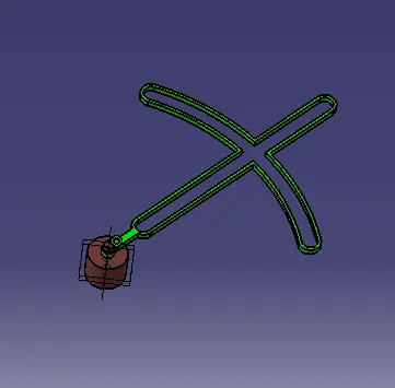
- Offset constraint:
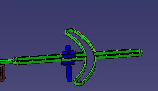
- Offset constraint at the length of 4mm.
- Similar use same operation to the other part body.
- Manipulation command:
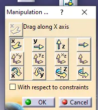
- a command is used to move the select the body part.
- darg around the axis is select the axis and select the surface and move the part.
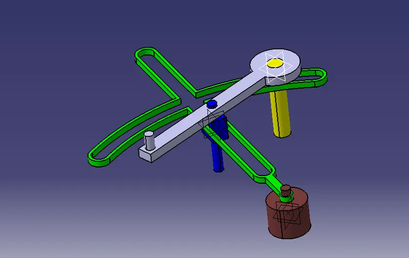
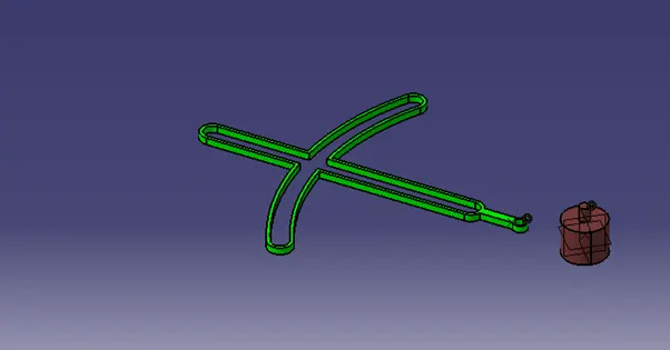
- FINAL BODY.
- Drawing sheet:
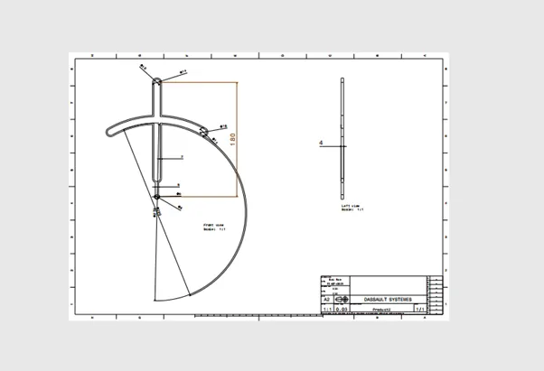
- use the dimension command to get a distance between the part body according to a requirement.
- go the same operation to the other part body.
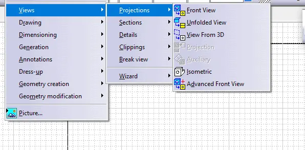
- By using projection view can select the required side of the part body.
- Use the tools accounting the requirement.
- Giving the length by using the dimensions.
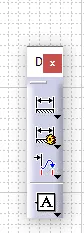
- By sheet back ground.
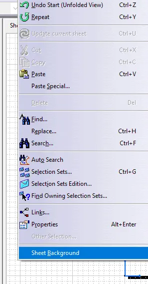
- Go to insert.
-
Select the drawing.
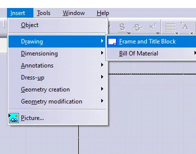
- Select the create and drawing title block sample 1 and sample 2.
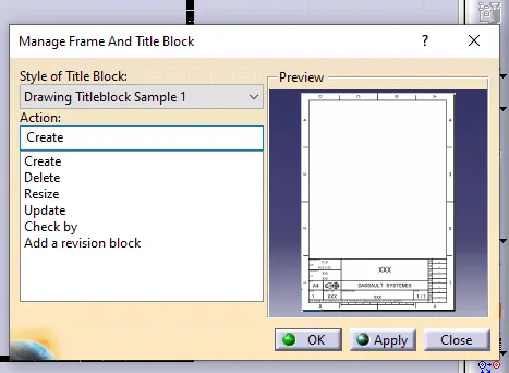
- press okay to apply
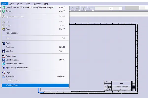
- Use working views.
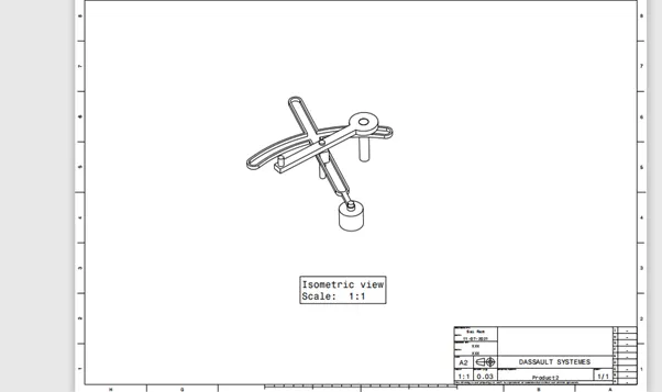
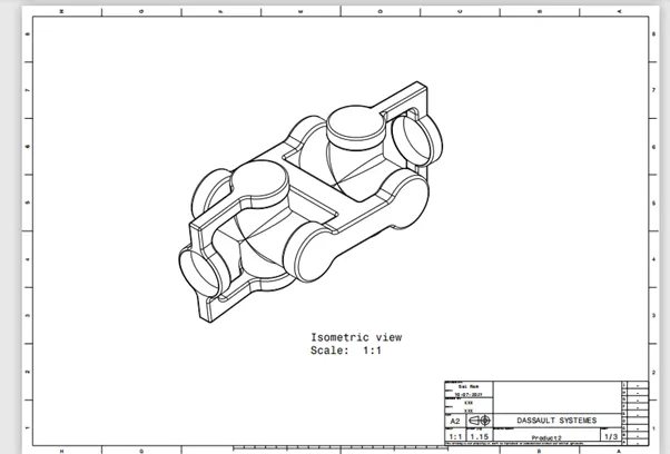
- The final output of the drawing sheet.
- CV JOINT ASSEMBLE.
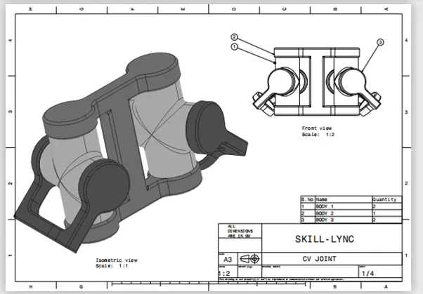
- overview of the 2d Complete the overview of the cv joint
- Then go the 2d draft and complete the
- overview of the 2d Complete the overview of the cv joint
- Then go the 2d draft and complete the
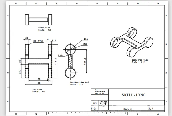
- Operation starts with draft and make sure every line is iso constrain.
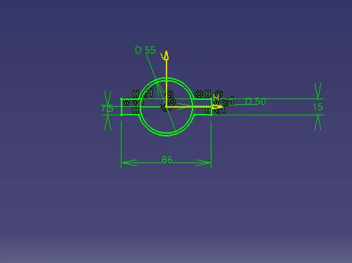
- Pad in the part design at the length 15mm.
- Make sure are in the different part body.
- Use the Boolean operation in the part design.
- To adding and removing.
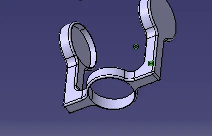
- Boolean operation is perfered.
- Used fillet at the edges at the angle 2mm.
- Similar operation done on other part body.
- Make every part body is support.
- ASSEMBLE DESGIN:
-
- Copy and paste special them as a result link.
- Go the similar operation to another part body’s also then it creates the tree structure.
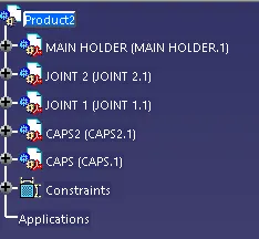
- Give the name that is required.
- the constraint is connecting the two bodies by using the update.
- Select the Contact opposite sides of the part body surface.
- the constraint is connecting the two bodies by using the update.
- Select the Contact opposite sides of the part body surface.
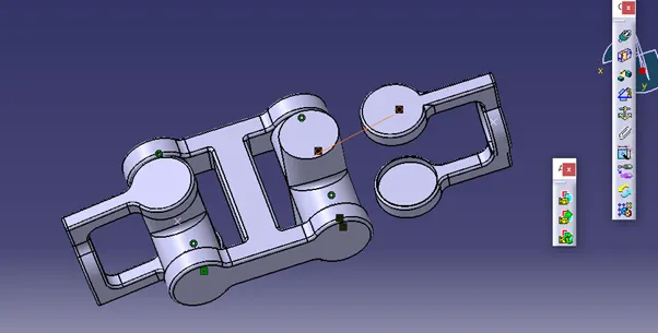
- Update to fix the position.
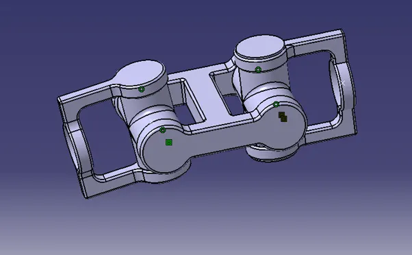
-
- The final output of the assemble.
- manipulation command.
- the command is used to move the select the body part.
-
darg around the axis is select the axis and select.
-
the surface and move the part.
-
Drawing sheet:
- Drawing sheet:
- ADD DIFFERENT SHEETS
- give the required length
- By using the dimension command.
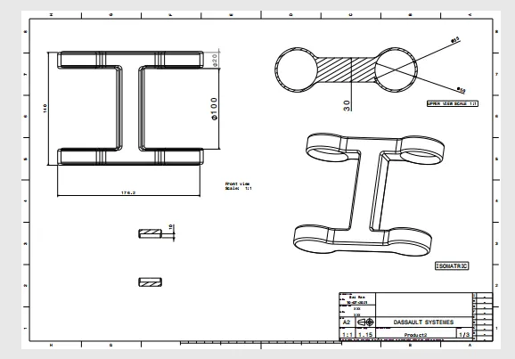
- A similar way goes the operation on the other parts also.
-
coming to title box:
- By using projection view can select the required side of the part body.
- Use the tools accounting the requirement.
- Giving the length by using the dimensions.
- By sheet background.
-
.Go to intsert
Select the drawing - Select the create and drawing title block sample 1 and sample 2.
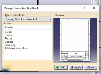
- Press okay to apply
- Use working views.
- To get on the sheet.
- thank you.