Week 11- Assembly Workbench
INTRODUCTION TO ASSEMBLY WORKBENCH IN CATIA V5
OBJECTIVES: The main objectives of this challenge are as given below
- To understand and learn how the tools work in assembly workbench.
- To design individual part bodies that are given in the challenge .
- To assemble the individual part bodies into a single assembly or product.
- To do drafting for the individual component and assembly as well.
- To prepare a detailed report explaining all the things which we have followed in the challenge.
ASSEMBLY OF QUICK RETURN MECHANISM
In this we have five individual comonents, so first let us discuss the aproach to design these comonents.
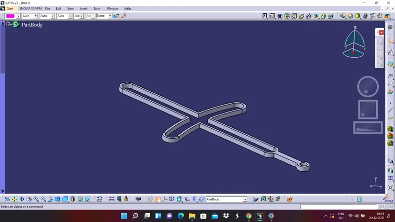
BODY 1
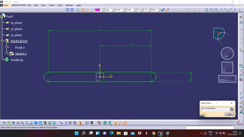
1. Create a sketch on the resective plane and make sure the sketch is constrained properly
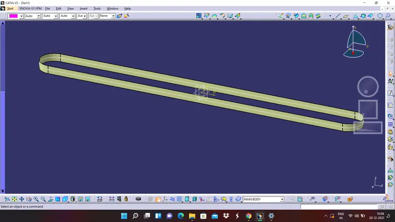
2. In surface workbench try to extrude the surface in resective direction and with correct value
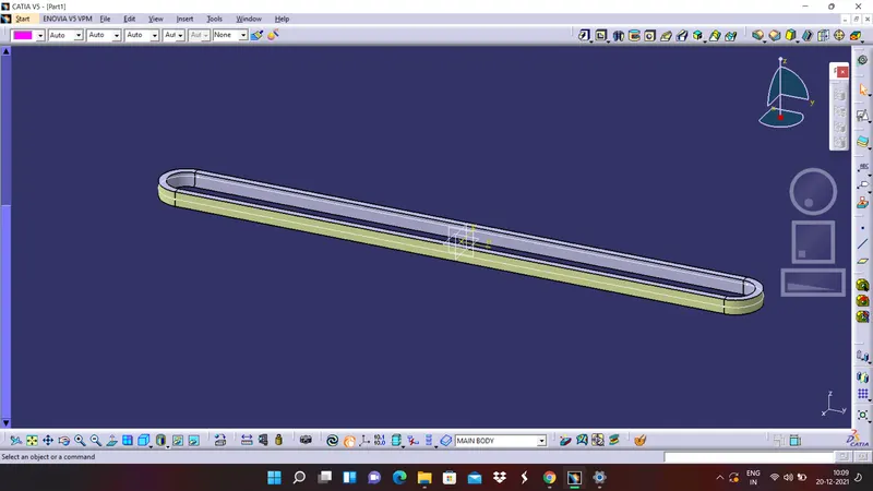
3. By using thick surface command in part workbench try to give required thickness to it
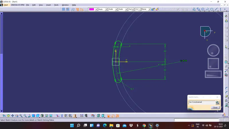
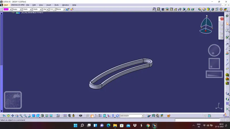
4. By using same sketch parametrs create another sketch for the side body
5. Now in similar to the main part extrude this sketch also
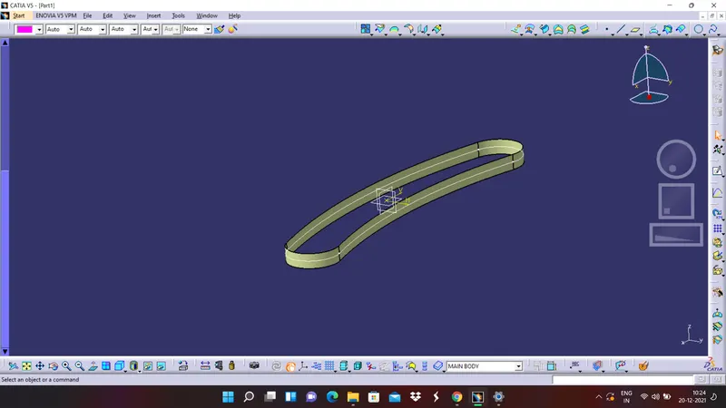
6. Now give some thickness to the extruded surface
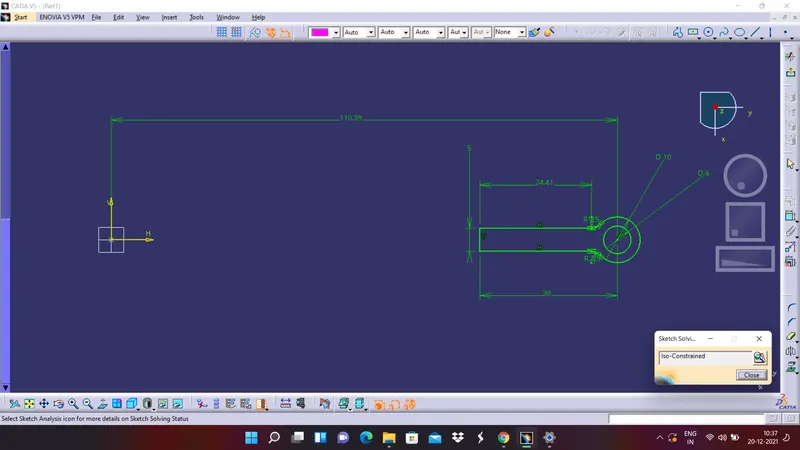
7. Create a sketch for the screw body and make sure it is constrained properly
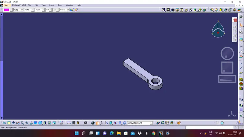
8. Pad the sketch to the required distance
9. Finally union trim the bodies and make them into a single body
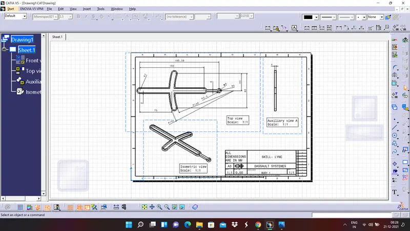
DRAFTING OF BODY 1:
BODY 2:
1. Create a sketch for the main circle and make sure it is constrained properly
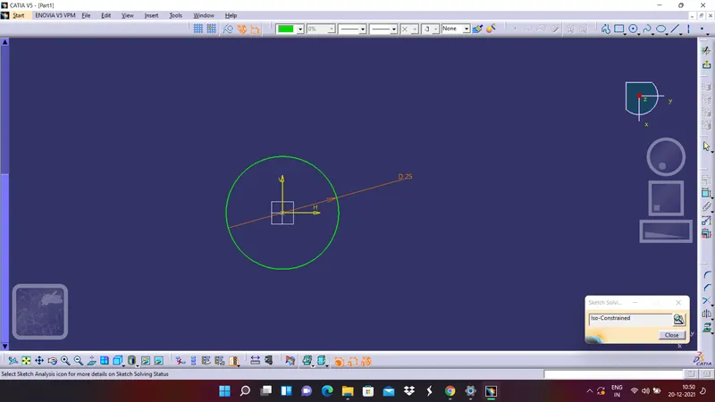
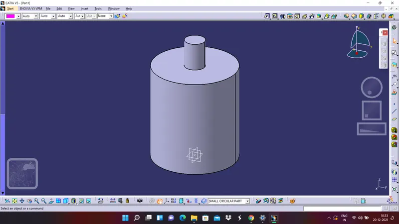
2. Pad it to the required distance
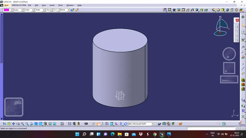
3. Create a sketch for smaller circle on the to
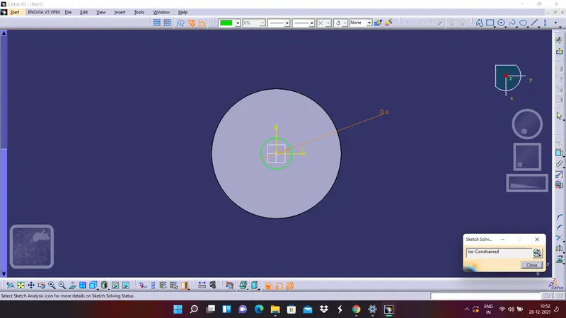
4. Pad it with the distance which is given
5. Finally add it to the big circular part
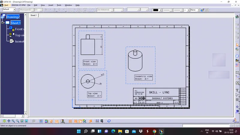
DRAFTING OF BODY 2
BODY 3
1. In the front view try to create a sketch of rectangular part
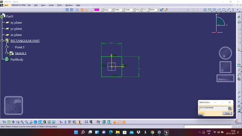
2. Pad it to the required distance
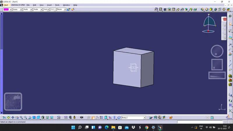
3. Create a sketch for the circular part
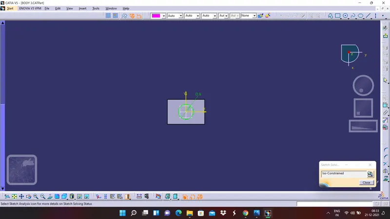
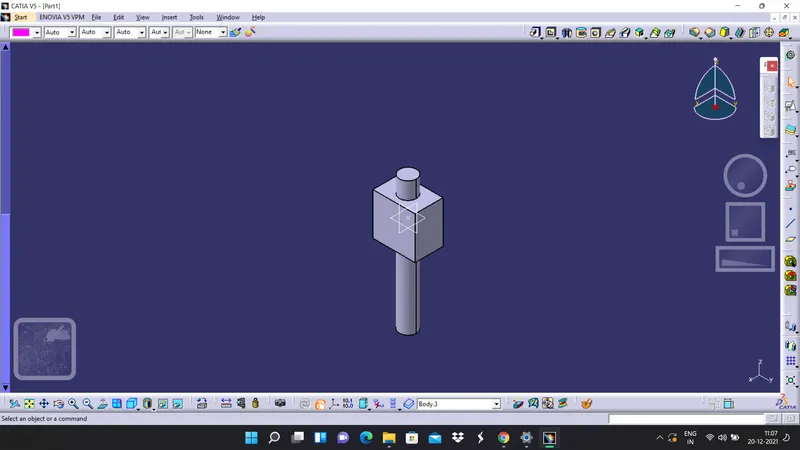
4. Pad it to the required distance and in the top and bottom directions and add it to the main body
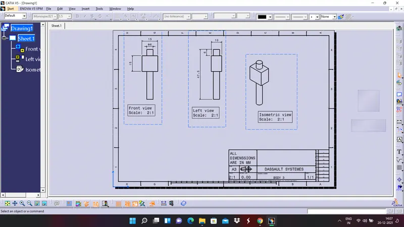
DRAFTING OF BODY 3
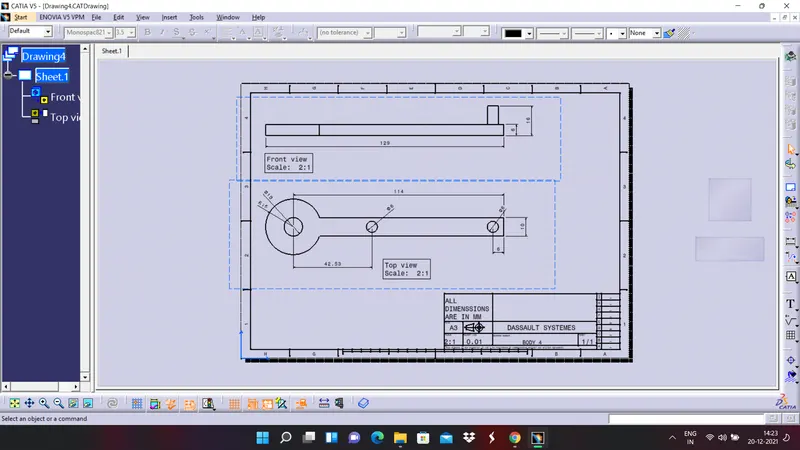
BODY 4
1. First create the bottom sketch
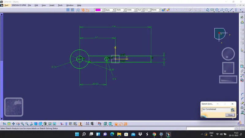
2. Pad it to the required direction and dimension
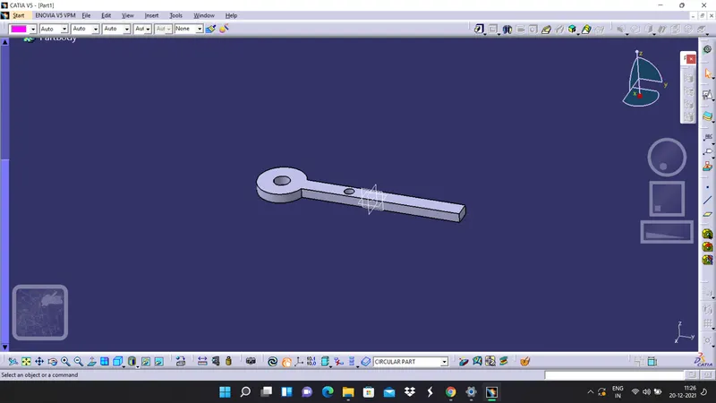
3. Create a sketch for circular part which is on the rear end
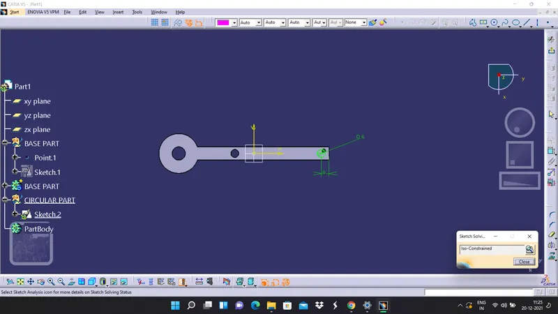
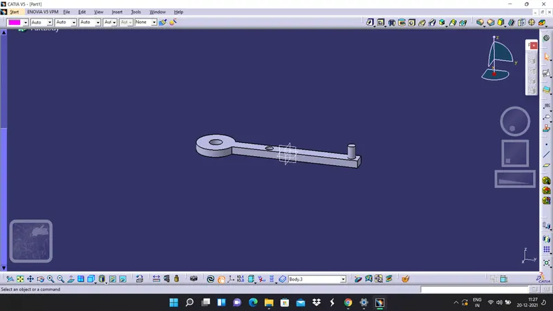
4. Pad it and add it to the main body
DRAFTING BODY 4
BODY 5
1. Create a sketch for circular part and make sure it is constrained properly
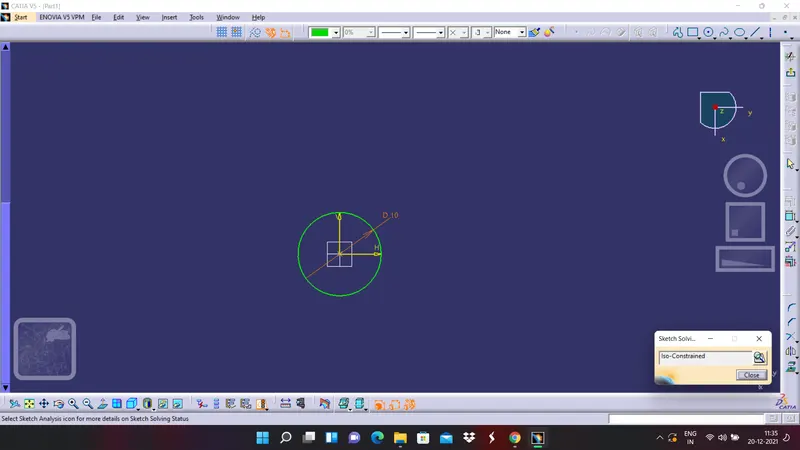
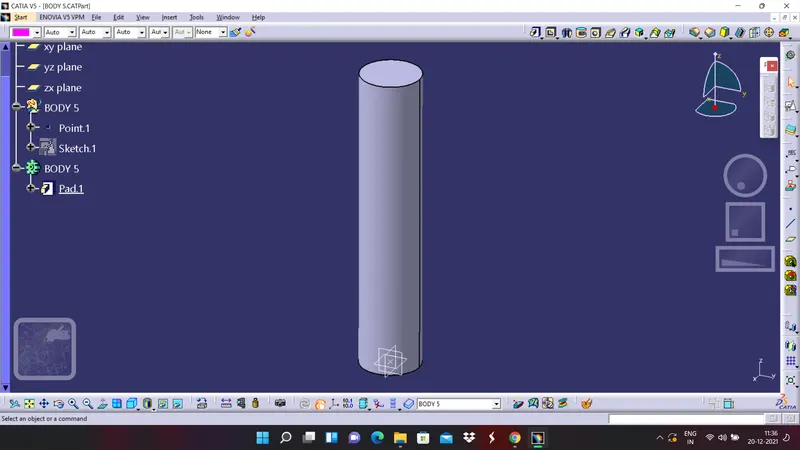
2. Pad it and add it to the main body
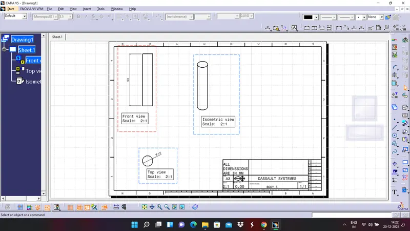
DRAFTING OF BODY 5
FINAL ASSEMBLY
1. Go to assembly workbench and activate the product and by using existing comonent command take all the bodies which we have created earlier.
2. Now apply proper constrains to the individual component create an assembly.
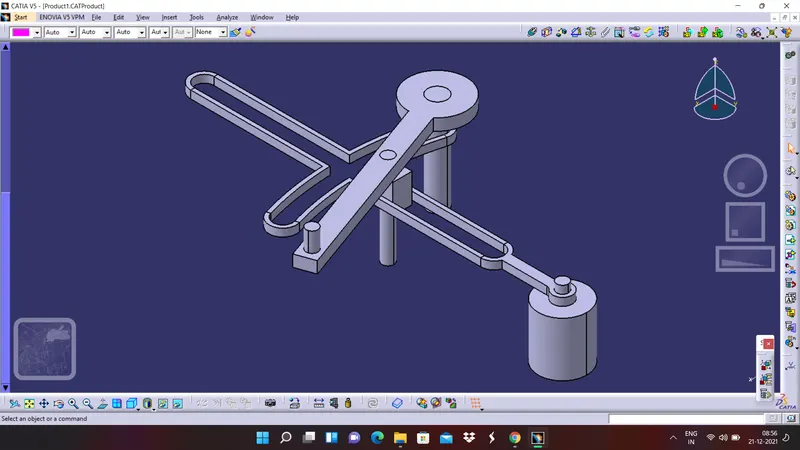
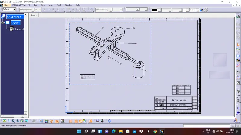
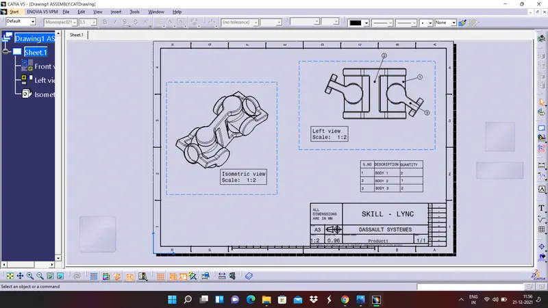
Create a drafting for the final assembly, since it is an assembly we have to include bill of materials also to the drafting.
ASSEMBLY OF CV JOINT
Here in the assembly of CV joint it contains three parts, so let us discuss how can we design those three parts
BODY 1
1. Create a sketch for vertical circular part
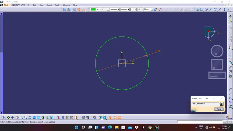
2. Now pad it to the required distance
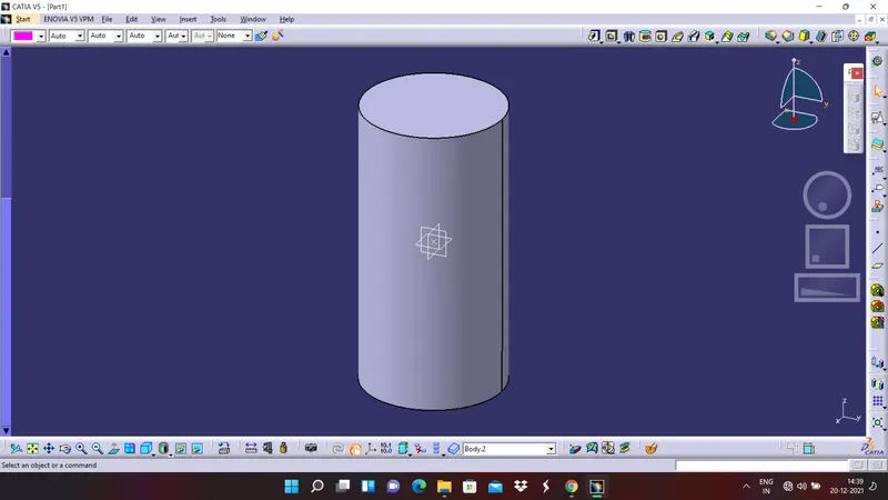
2. Now create a sketch for horizontal cirlce and make sure it is properly constrained
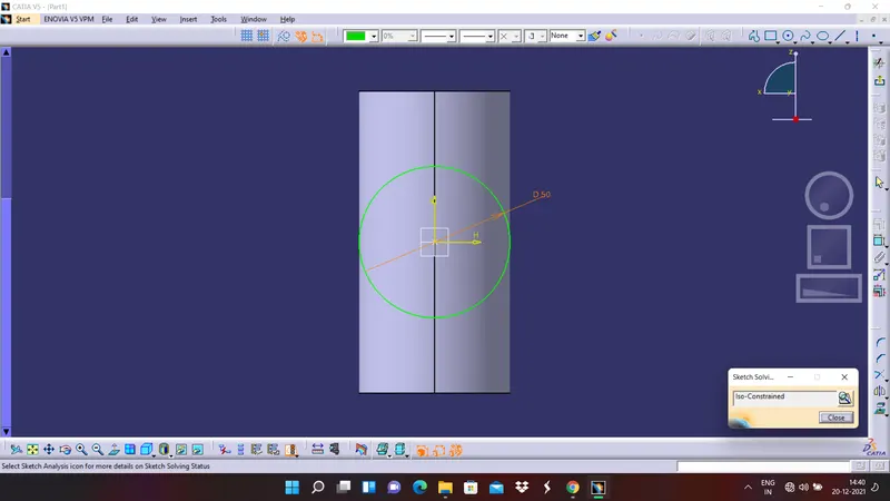
3. Now pad the horizontal circle
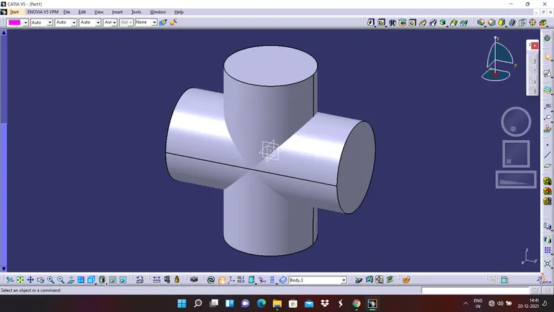
4. Add them together and apply edge fillet to it
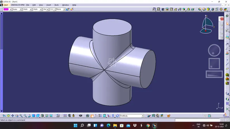
DRAFTING OF BODY 1
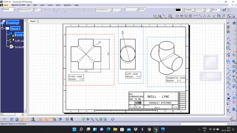
BODY 2
1. Now create a sketch for the circular portion of the body
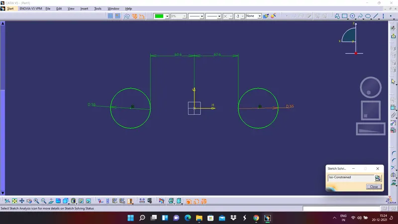
2. Pad it the sketc to the required distance
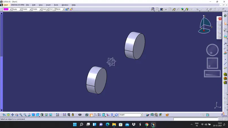
3. Shell the paded circles to the required dimenssions
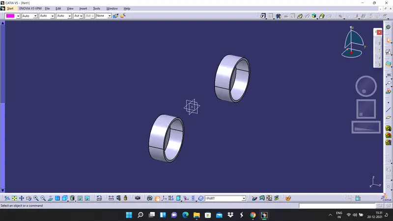
4. Now create a sketch for I cross-section between the two circles
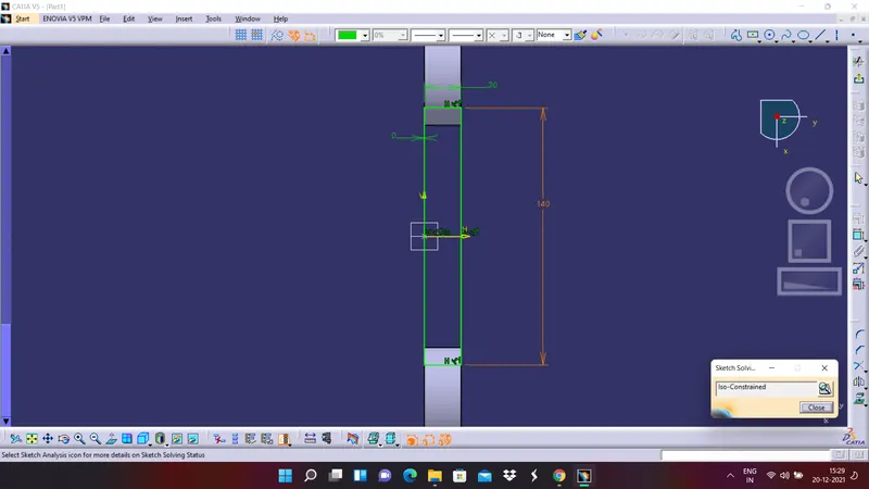
4. Pad it to the required distance
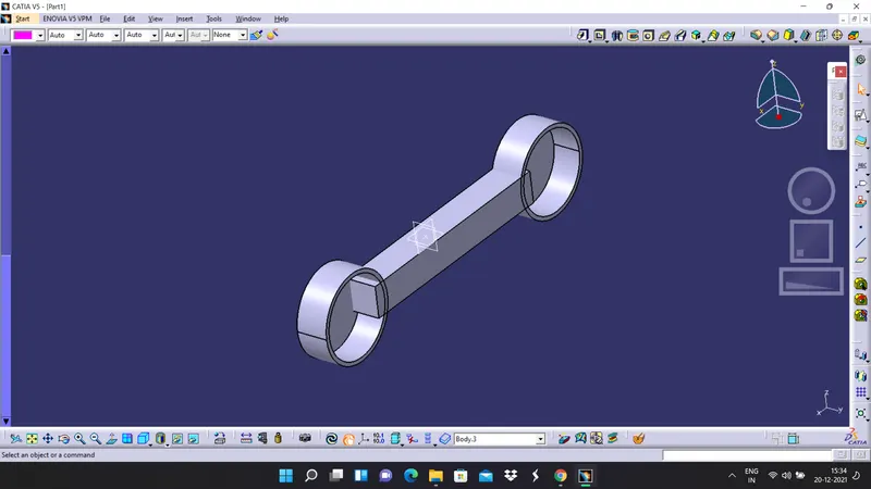
5. Union trim the two bodies to get the required shape
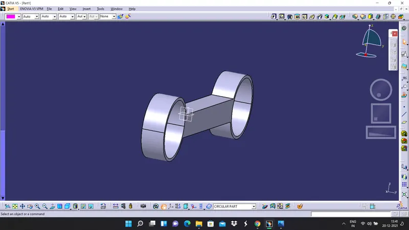
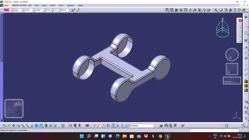
6. Now by taking the plane at the centre mirror the part to the other side
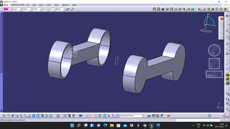
7. Now let us create a sketch for the H cross section to connent these two objects
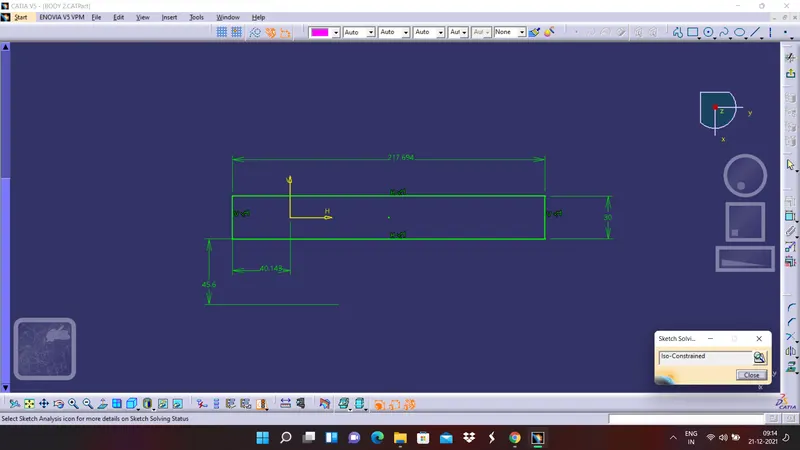
8. Pad it and union trim with the previous body
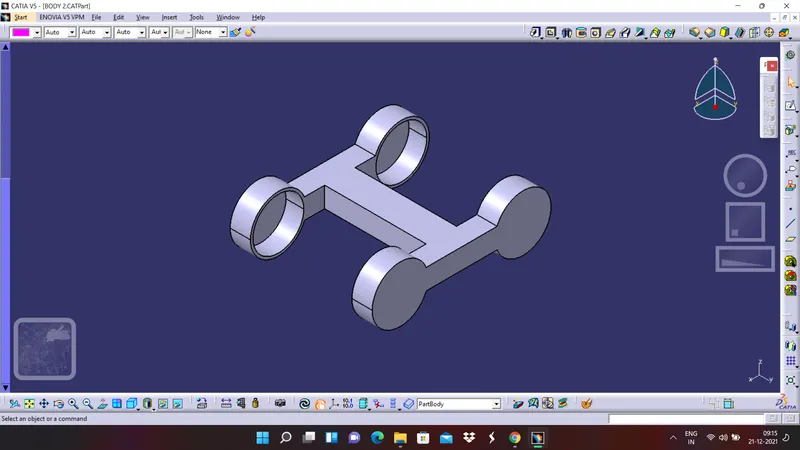
9. Finally apply edge fillets with proper radius.
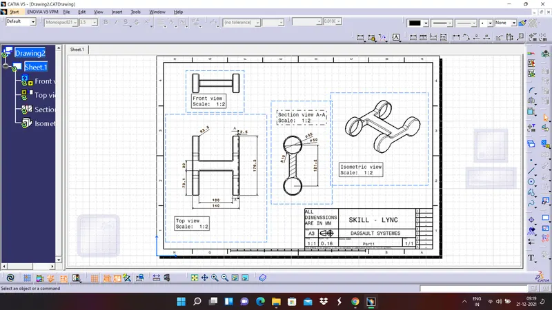
DRAFTING OF BODY 2
BODY 3
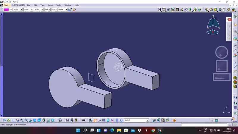
1. Create a sketch of the front view and make sure it is constrained properly
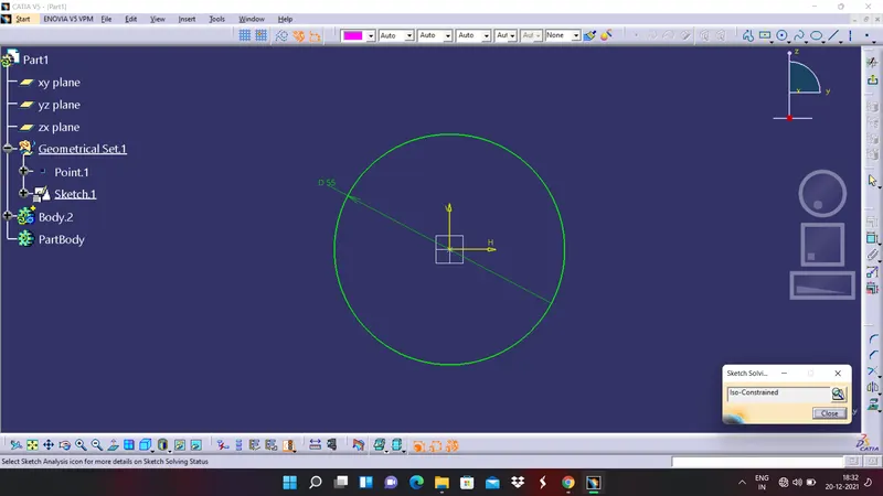
2. Pad it to the required distance
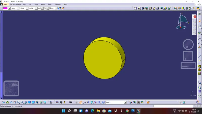
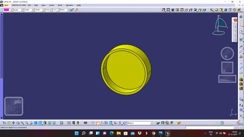
3. shell it
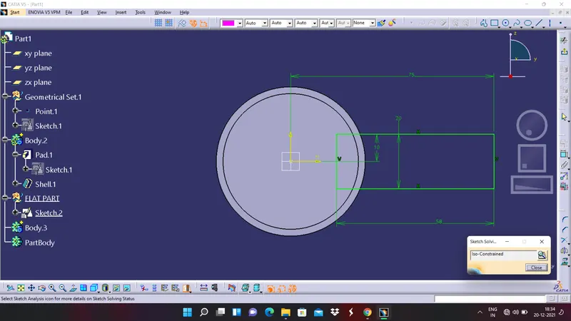
4. Create a sketch for rectangular art which is attached to it
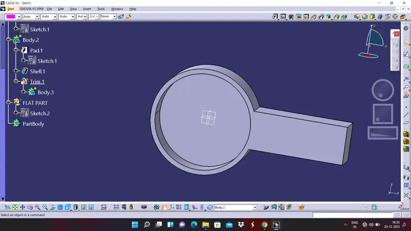
5. Pad it to the required distance and union trim both the bodies
6. Mirror it by creating a plane at the centre
7. Create a sketch for side part and make sure it is constrained properly
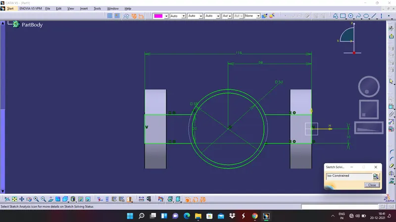
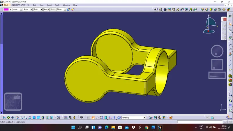
8. Pad it with required distance and add it to the previous body
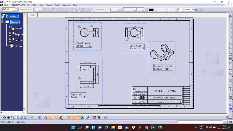
DRAFTING OF BODY 3
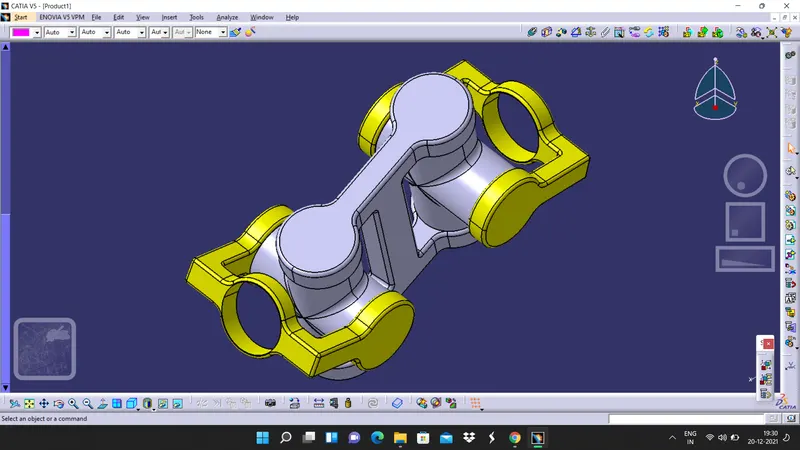
FINAL ASSEMBLY OF CV JOINT
1. Go to assembly workbench and activate the product and by using existing comonent command take all the bodies which we have created earlier.
2. Now apply proper constrains to the individual component create an assembly.
DRAFTING OF FINAL ASSEMBLY:
CONCLUSSION
Thus, we are concluding that that we have created 3d part bodies of individual and components and their drawings, we have also assembled the bodies and created assemblies. A proper report has been prepared and all the images are attached to the challenges successfully.