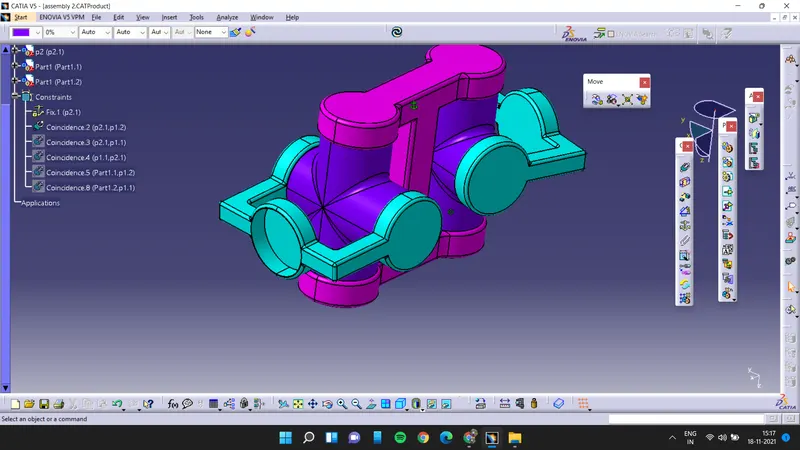
Week 11- Assembly Workbench
- AIM :
To create assemblies according to the provided with 2D diagrams of the components by first creating the individual part files and then create a complete assembly of those part files in the assembly
THEORY :
Assembly modeling is the process of creating designs that consist of two or more components assembled together at their respective work positions. The components are brought together and assembled in Assembly Design workbench by applying suitable parametric assembly constraints to them. The assembly constraints allow you to restrict the degrees of freedom of components on their respective work positions.
- Types of Assembly Design Approach :
In CATIA you can create assembly models by adopting two types of approaches. The first design approach is the bottom-up approach, and the second one is the top-down approach.Both these design approaches are discussed below.
1.Bottom-up Assembly -
The bottom-up assembly is the most preferred approach for creating assembly models. In this of approach, the components are created in the Part Design workbench as (*.CATPart) file. Then the product (*.CATProduct) file is started and all the previously created components are inserted and placed in it using the tools provided in the Assembly Design workbench.
After inserting each component, constraints are applied to position them properly in the 3D space with respect to other components.
2.Top-down Assembly -
In the top-down assembly design approach, components are created inside the Assembly Design workbench. Therefore, there is no need to create separate part files of the components.
This design approach is completely different from the bottom-up design approach. Here you have to start the product file first and then, one by one, create all components. Note that even though the components are created inside the product file, they are saved as individual part files and can be opened separately later.
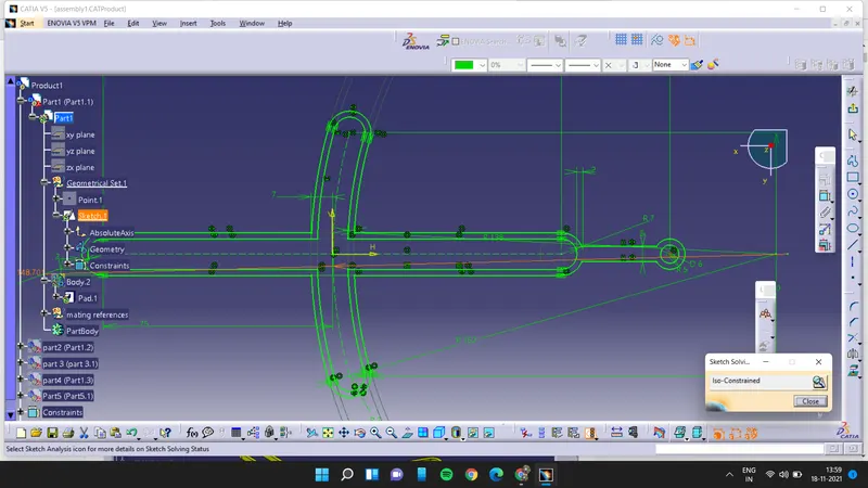
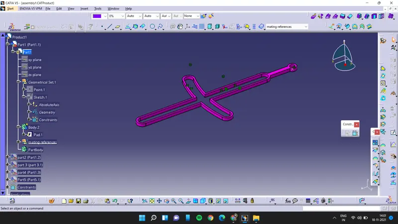
part 1:
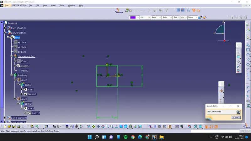
part 2:
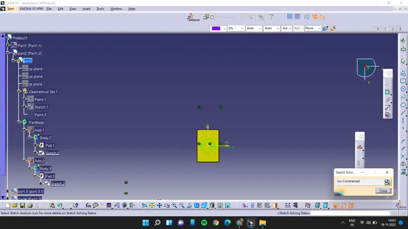
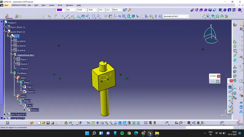
part 3:
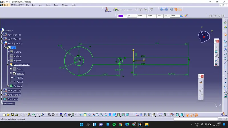
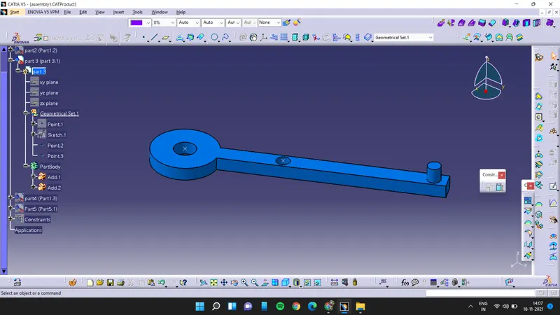
part 4:
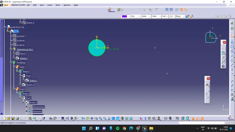
part 6:
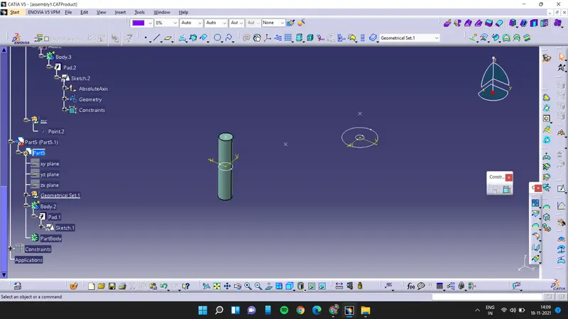
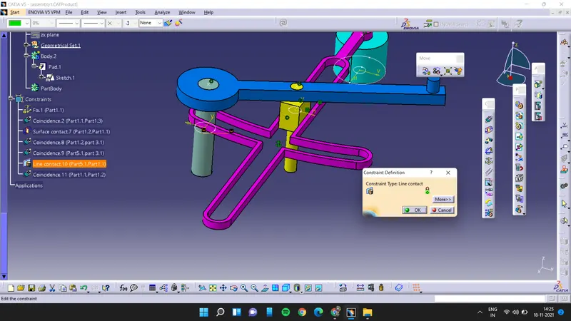
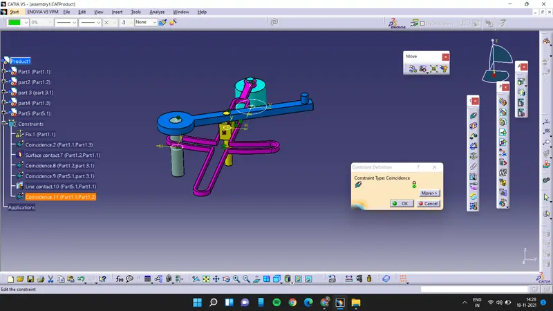
after drawing and padding all the parts first we have to open the assembly workbench of catia v5
first we have to fix one part
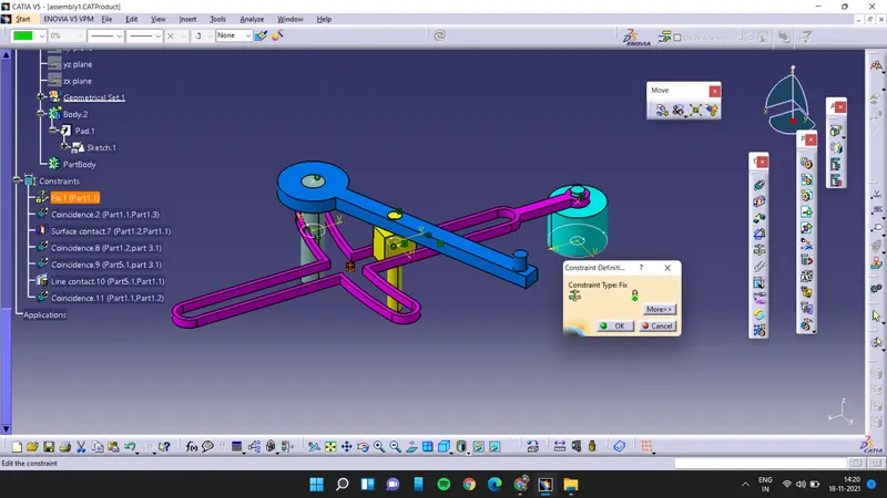
then use coincidence constraints to join the end and part 3
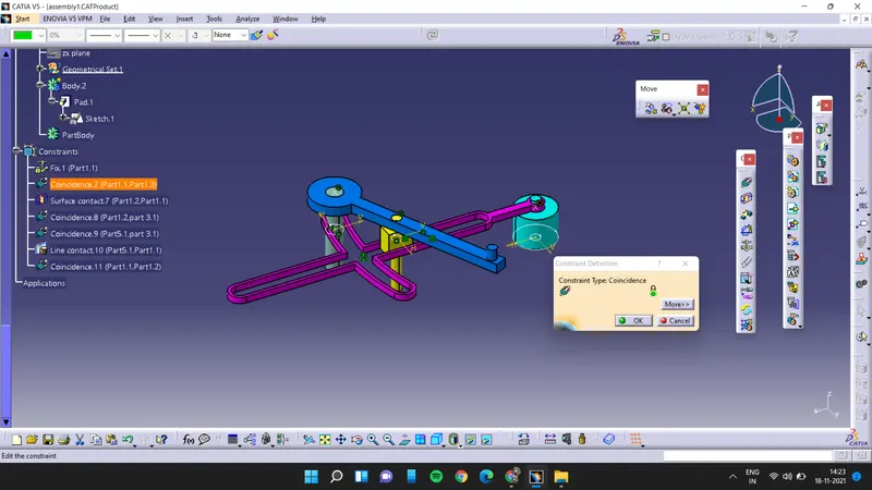
then using surface constraint to connect the part 2 and the part 1 also the top is constaint with coincidence constraint also left edge is constaint with the fix part
Assembly 2:
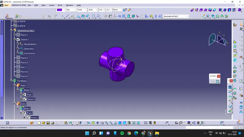
Part 1
PART 2:
PART 3:
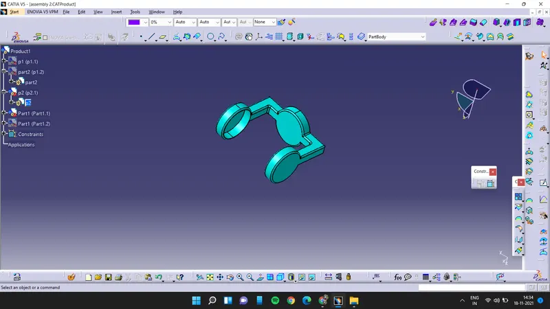
process:
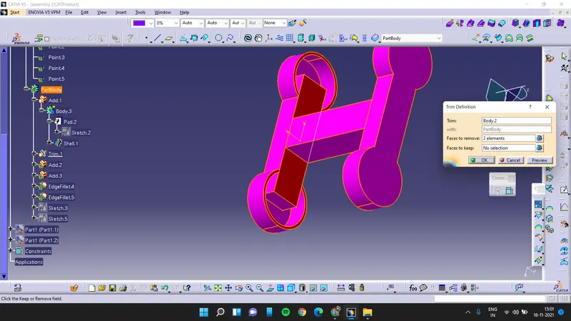
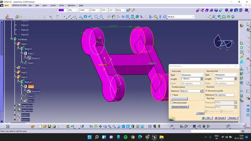
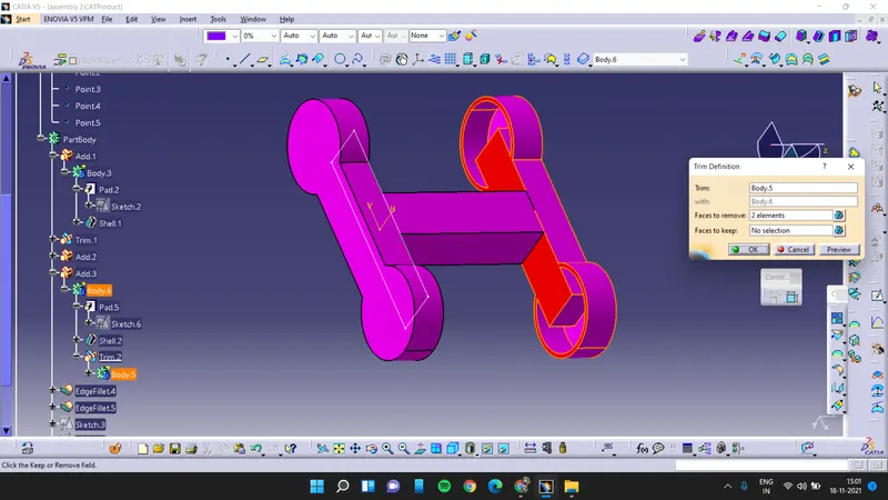
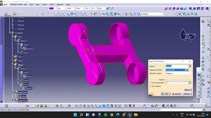
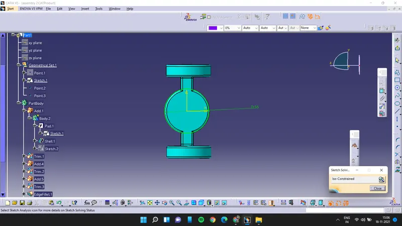
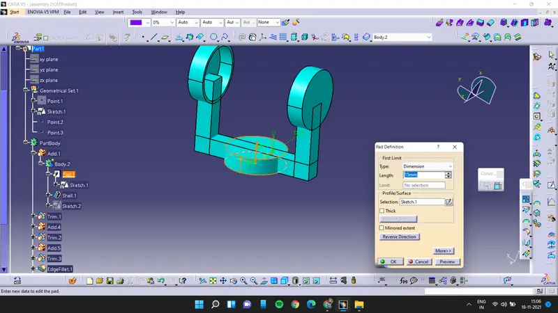
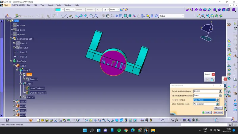
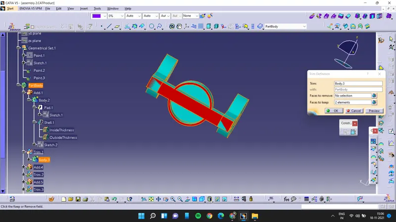
creating the sketches for the first part and the padding it and adding it and then applying fillets to it
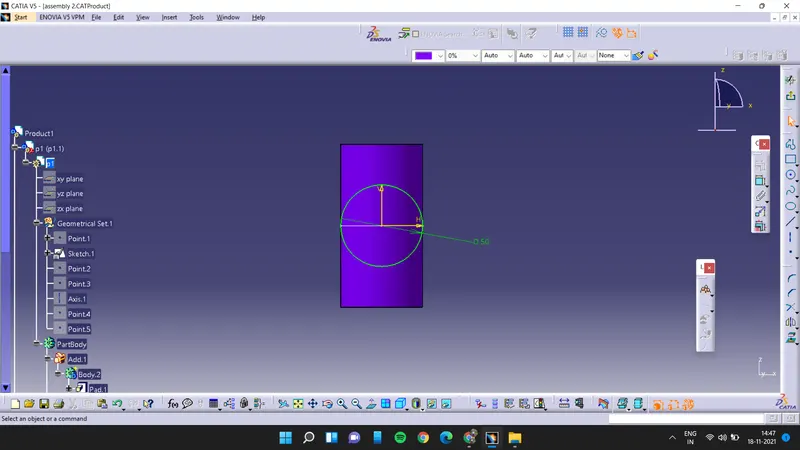
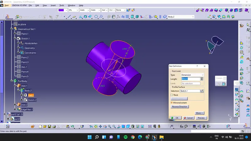
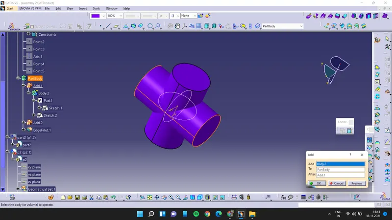
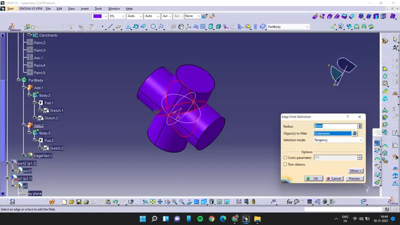
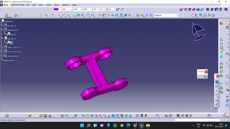
part 2
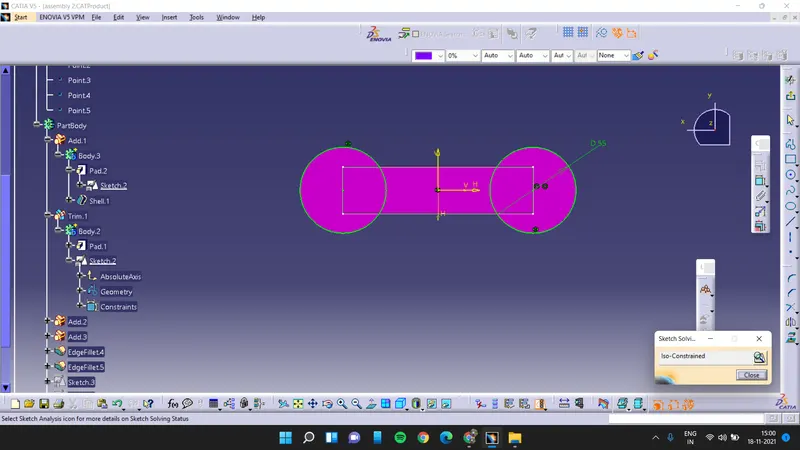
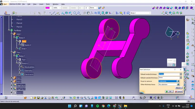
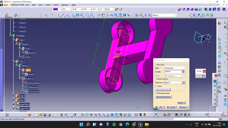
Part 3:
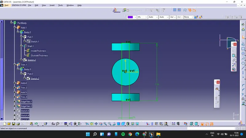
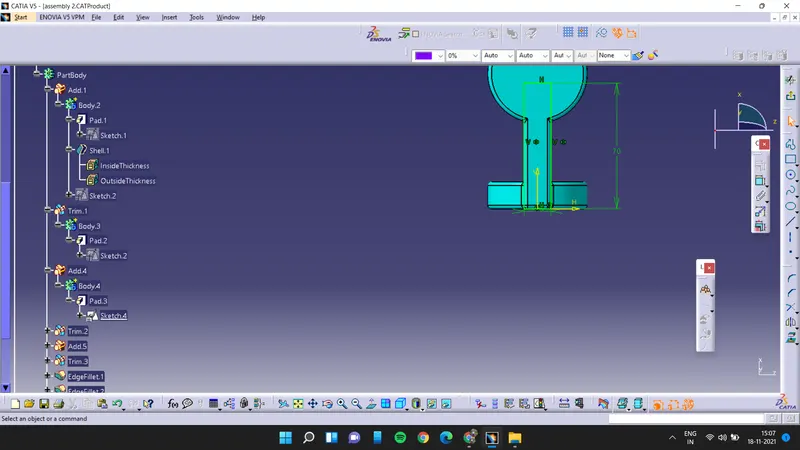
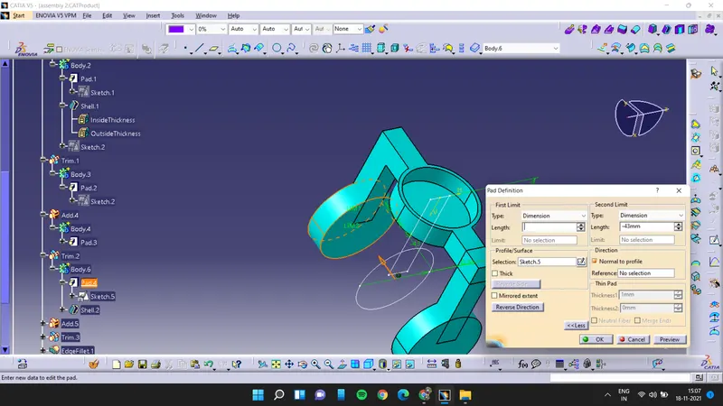
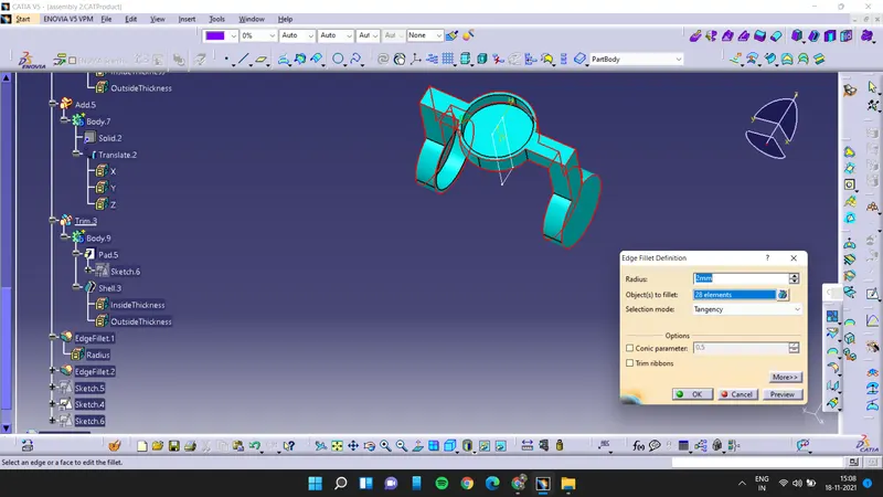
after creating all the parts we need to assemble it for assembly we have to import all the parts in assembly workbench then we have to fix the middle part i.e. part2 by using fix option and then we have to assemble the part 1 on the fixed part by using coincidence constraint
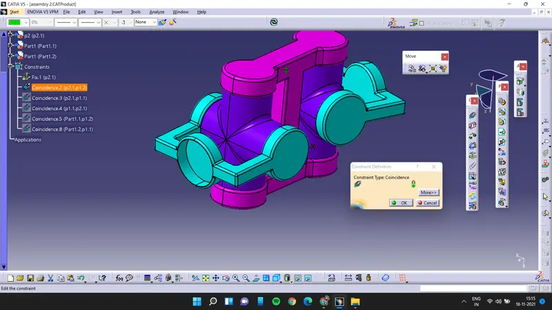
then connect the part 3 with the part 1 by using coincidence constraint and do the same to the other side it will complete the assembly
final product
assembly 1
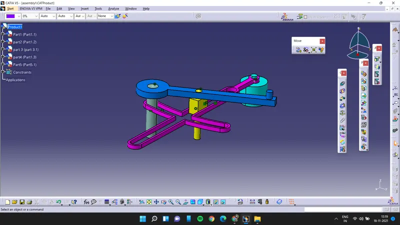
assembly 2