Radar Mast & Final Assembly of Yacht
Project Report
Modelling Sunseeker Predator Yacht
Index
- Introduction
- Design Approach
- Features
- Modelling of parts
- Assembly
- Rendering
- Special Mention
Introduction
This project is all about modelling of different parts of Modelling Sunseeker Predator Yacht and then assembling all the parts to make a great looking machine. And this project contains rendering and photo view 360, which gives us a realistic and natural view and it comes so natural that it just treat to our eyes after this all hard work.
Design approach
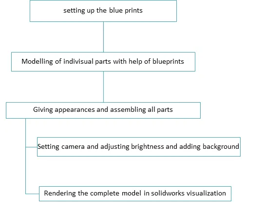
For every modelling design there are two approaches one is top to bottom approach and other is bottom to top approach for this assembly we are using bottom to top approach. Design is starts with the modelling of engine component like propellers and then components which are attached with the hull like superstructure seats etc. following flow chart shows all the information about each and every step.
Index
- Introduction
- Design Approach
- Features
- Modelling of parts
- Assembly
- Rendering
- Special Mention
Introduction
This project is all about modelling of different parts of Modelling Sunseeker Predator Yacht and then assembling all the parts to make a great looking machine. And this project contains rendering and photo view 360, which gives us a realistic and natural view and it comes so natural that it just treat to our eyes after this all hard work.
Design approach
For every modelling design there are two approaches one is top to bottom approach and other is bottom to top approach for this assembly we are using bottom to top approach. Design is starts with the modelling of engine component like propellers and then components which are attached with the hull like superstructure seats etc. following flow chart shows all the information about each and every step.
Features
Features Plays an important role in solidworks modelling it helps to make different shapes, cuts on surfaces and on solid bodies. Let us discuss all the features which we have used in modelling of this chopper
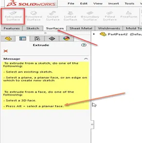
- Surface Extrude: Using the SOLIDWORKS Surface Extrude feature, we can extrude the boundary edges of a face of a solid body or edges of a surface body in a customized direction. When we run the Extruded Surface command, two things can happen: Either a sketch is active or preselected or no sketches exists. In case no sketches exist or is selected, a message in yellow color shows in the property manager window on the left. The message is guiding us to select a sketch or a planar face to start drawing a sketch for extrusion purpose. In addition, the message guides us to extrude from a 3D face or use “Alt + planar face” to extrude.
- Fillet: Fillet/Round creates a rounded internal or external face on the part. You can fillet all edges of a face, selected sets of faces, selected edges, or edge loops. We can use different types of fillets according to shape of our model Such as Round fillet, constant radius, multiple radius.
|
|
|
|
|
|
|
|


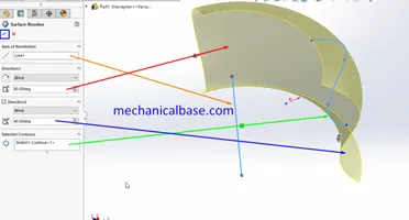
- Revolved surface: A revolved feature must contain an axis of revolution. Create an axis of revolution either by sketching a centre line with the revolved section, or by selecting existing linear geometry.
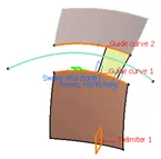
- Swept surface: Sweep Surfaces are surfaces that are generated from a section curve positioned along a path. You can create a swept surface by sweepingout a profile in planes normal to a spine curve while taking other user-defined parameters (such as guide curves and reference elements) into account.
- Lofted surface: It is the simplest way to allow the software to interpolate a shape between two or more profiles. It works with solids and surfaces, and it has unique functions as well as some overlap with the Boundary feature. Loft has several unique functions like Closed Loop, centreline loop.
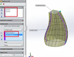
- Filled surface: The Filled Surface feature constructs a surface patch with any number of sides, within a boundary defined by existing model edges, sketches, or curves, including composite curves. You can use this feature to construct a surface to fill a gap in a model.
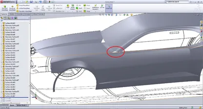
- Offset surface: In surface models, use this tool to offset model edges and faces onto surfaces. The tool adds a 3D sketch entity on the surface. Geodesic Offset Creates an offset distance that is the shortest possible distance between the selected edge and the resultant offset entity, taking the support curvature into account.
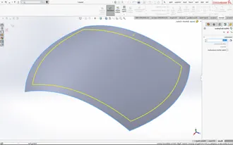
- Ruled Surface: The Ruled Surface command is a very versatile command that can create several different types of surfaces. It will create surfaces at an edge relative to an existing surface. All it takes is just an edge and a user input distance. With that, the Ruled Surface can add new surface geometry in the ways such as Tangent to Surface, Normal to Surface, Tapered to Vector, Perpendicular to Vector, Sweep.
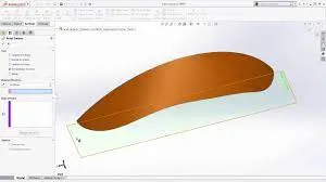
- Delete face: The Delete Face Feature allows the user to efficiently remove faces by maintaining multi-selection facility. There are many options available within the delete feature – Delete, Delete and Patch, and Delete and Fill.
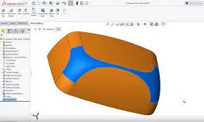
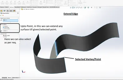
- Extend surface: You can extend a surface by selecting an edge, multiple edges, or a face You can propagate extended surfaces to tangent faces by clicking the Propagate callout which appears only if you select edges.
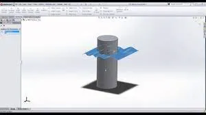
- Trim surface: It is used to trim two or more intersecting surfaces You can use a surface, plane, or sketch as a trim tool to trim intersecting surfaces. You can also use a surface in conjunction with additional surfaces, as mutual trim tools.
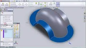
- Knit surface: The Knit Surface tool is used to combine two or more faces and surfaces into one. Edges of the surfaces must be adjacent and not overlapping. Surfaces do not need to be on the same plane. Select the entire surface body, or select one or more adjacent surface bodies.
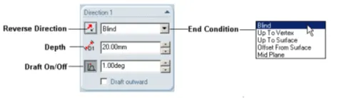
- Extrude Boss/Base: An Extruded Boss/Base feature will allow you to take a 2D sketch and add thickness to it in the third dimension. Every few releases, this feature gets some terrific functionality added to it. To perform extrude we shouldn’t forget to give the accurate directions like from blind or up to the surface or mid points etc.
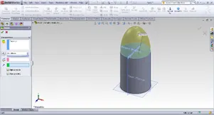
- Dome: Dome, in architecture, hemispherical structure evolved from the arc, usually used to form a ceiling o roof over a selected face or surface.
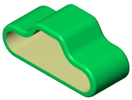
- Shell: The shell command is used to create a thickened surface, either it can be done in interior or exterior surface.
Modelling of parts
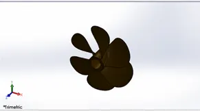
1.Propeller: Propeller is the outermost part of the engine of yacht for creating the propeller model first we have to use boss/base revolved feature to create the middle component of the propeller then by using boss/base loft feature first fin is modelled then applying fillet to make edges smooth and then by using circular pattern all fins are modelled then appearance to the body is applied.
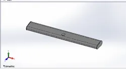
2.Radar: Using the sketch and boss/base extrude the outer model is created then fillet is applied convert all edge into a curved shape. Then by using boss base extrude, cut extrude and linear pattern four entities are created on the one edge and then the total body is mirrored from the middle and then the hole is created in thr middle.
3.Blueprints: Blueprints are very useful to create any model for this yacht the front view of the blueprint is inserted on the front plane with some values then according to positions back view top view side view and bottom view is also inserted on front plane right plane top plane according to the need and also by reminding that the horns of yacht should be on the same side front view and back view is adjusted. 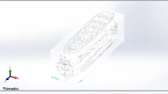
4.Hull: For modelling the hull first we have inserted the blue prints and then the by using sketches we have created the outer surface by surface extrude feature then the deck surface is created by fill surface feature by selecting boundary surfaces and then window is created by using extrude cut and then window is copied and patterned by using linear pattern option round outer boundary is modelled by swept surface and creating planes. Then the railing is modelled by projecting curves and then swept boss base is used to give a round profile to the railing and the extra portion is removed. After creating all the parts the entire side is mirrored to make the entire hull. And at the end decals are applied on the surface of deck and all other surfaces on the hull. 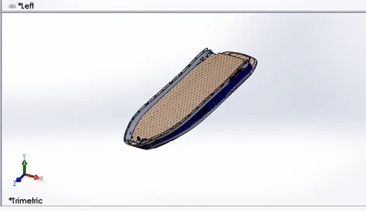
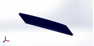
5.Garage door: Garage door is created from the garage part which is removed from the hull. First we took the part which is delete from the garage section by using split tool then created the one side of the door and applying fillets to the outer edges then and then hole is created and one end and the part is mirrored with respect to the middle surface by using knit surface and mirror feature.
6.Front seat: Designing of front seat started with creating the curves with reference to blueprint. The major features used during designing of front seat were surface loft, surface trim, surface knit, cut extrude. A dome was also used to create mattress like appearance on the seat. The mattress was provided with light gray color whereas the other seat surface with white color.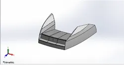
7.Middle Seat: Middle seat is located behind the superstructure. It was created with reference of blueprint on hull surface. One table was also created with the middle seat. For this first we inserted the blue prints and then hull surface is also inserted then by using boss extrude chamfer and fillet the seat with the table is modelled. 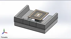
8.Rear seat: It is created with reference of blueprint on hull surface it is first crated as closed surface body and then converted into solid body. While designing rear seat I first create closed surface body of half seat by using surface tools like sweep, trim, knit and loft. Seat was first designed half and then it was mirrored to get the full seat. 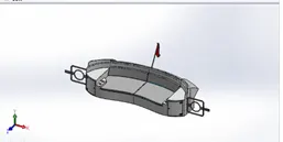
9.Super structure: The designing of superstructure was totally based on the 3d curves and 3d sketches. 3d curves were created by projecting two different sketches which were made with reference to blueprint. The most frequently used tools while designing superstructure were surface loft, surface trim, surface knit, surface fill and extended surface. Wind shield and other windows were provided with dark colour and other part of superstructure with white appearance. Superstructure is an multi body part which consists of cockpit, table, viper, window. It was also designed half and then mirrored about mid plane. 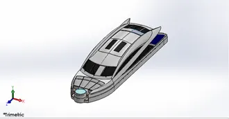
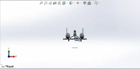
- Radarmast: It’s a mechanism used for the navigation of the ship. It’s a multi body part consisting of antenna, navigation light, fog horn and radar scanner. First the surface of super structure and blue prints are inserted then by using sketches, Boss extrude, sweep, revolve, fillet the half part is created and then all parts are mirrored and then appearances are applied to the model.
Assembly
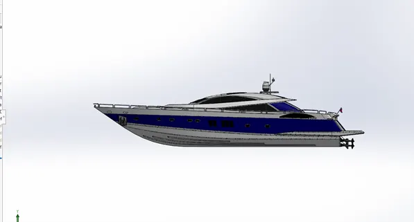
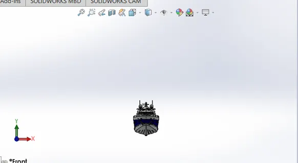
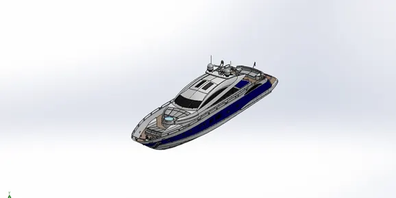
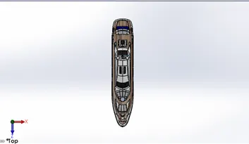
After modelling of all parts is completed assembly is the only thing which brings all the part together and gives us a desired machine for which we are working for firstly we have to open a solidworks assembly and then we have to insert the hull of the yacht and then we have to insert the super structure it will automatically fix with the hull then we have to bring radarmast, front seat and middle seat it will fixes automatically on the hull then we need to bring the rear seat and by giving mating relations like coincident mate to the surface and distance mate from end surface the rear seat fixes with the hull surface. Then we insert the garage door and give the coincident mate to the hole and then by giving coincident mate to the mid plane of hull and right plane of hull the garage door is fixed. And after the door propeller is inserted and it is also fixed by coincident and concentric mates and same propeller is inserted and fixed with the hull body. And then at last the radar is fixed on the radarmast by giving concentric and coincident mate relation to the hole of radar and the radarmast.
Rendering
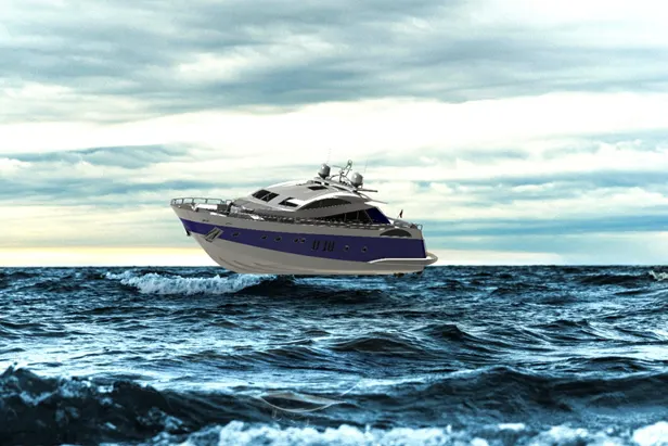
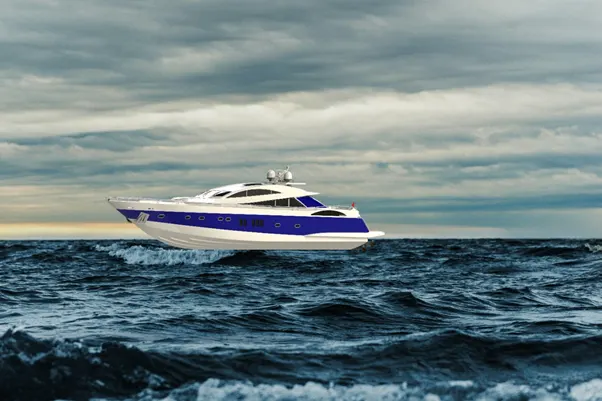
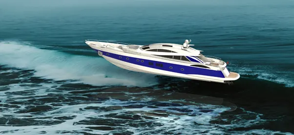
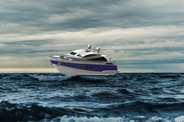
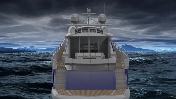
Rendering gives a realistic and natural look to the yacht. But before that camera view and setting the desired lights and we also added the ocean background which gave a realistic view to the yacht. Later on the yacht model is taken to solidworks visualize where we adjusted the brightness of environment and gamma values so that the outcome looks more realistic. And then we performed the rendering.
special thanks
I am highly indebted to Abhiteja Padma and all other faculties of skill-lync for their guidance and constant supervision as well as for providing necessary information regarding the project & also for their support in completing the project.
Thank you.