Week 8 - Challenge 1 - Draft Analysis on a Fan Cover
DRAFT ANALYSIS REPORT:
- Draft:
Draft is an angular tapering given at the design stage to every Plastic Component that has to be manufactured. It is given in the direction of the Mold Movement. The Draft allows the parts to release easily from the mold without creating friction between the surface of component and the core and cavity plates.
When a Plastic component cools down inside the mold, the natural tendency of it is to shrink and attach to the core or cavity half. The movement of mold opening causes friction on the walls of the component as well as the core/cavity blocks. This reduces the life of the mold as well as the component itself. The component may also have rough surface finish as well as weak structure due to this. This problem can be solved by giving draft to the component.
- Draft Analysis:
Draft Analysis is a tool in CATIA which identifies the zones which deviates from the specified values of angles along a defined draft direction using colour codes. It highlights the regions of draft using colours. Draft analysis is the first step performed after receiving the Class A of the component.
- Draft Angle:
This is the angle that the draft faces make with the pulling direction. This angle may be defined for each face.
- Tooling Axis:
Tooling axis defines the mold or core and cavity opening direction. we should create a tooling axis in such a way so that it should cover most of features,holes,geometries and most of the crossectional area.
- Procedure to be followed

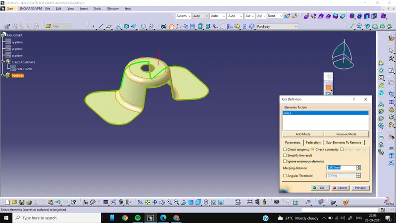
First ensure the class-A surface is properly closed and has no discontinuity on it. For this we have use boundary command or join command.
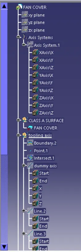
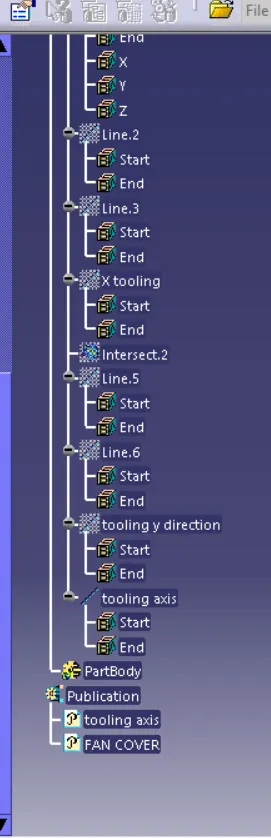
analyze the model manually or visually to see which direction is most suitable for tooling axis. From the Z direction the hole is visible so we choose this direction for tooling axis.This axis is called dummy axis. Now we will use bisecting method to make the real tooling axis Make an axis system and intersect the ZX plane with the class-A surface. We will get the line. Now we have to see which surface will create problems or will be difficult to be tooled and make a line along that surface using point to point option. Here we can see in the picture that we have made two lines, now we will bisect the lines and choose proper direction, here vertical direction. This will be our tooling axis for X direction, And same procedure is followd for y direction.
Tooling axis x-direction
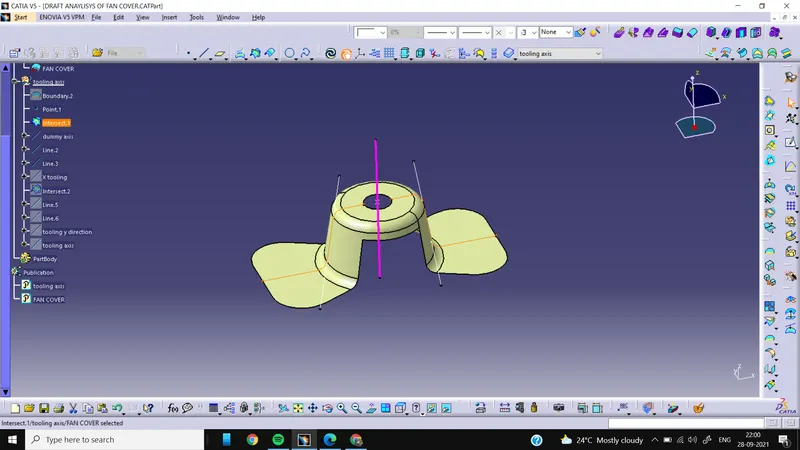
tooling axis Y-direction:
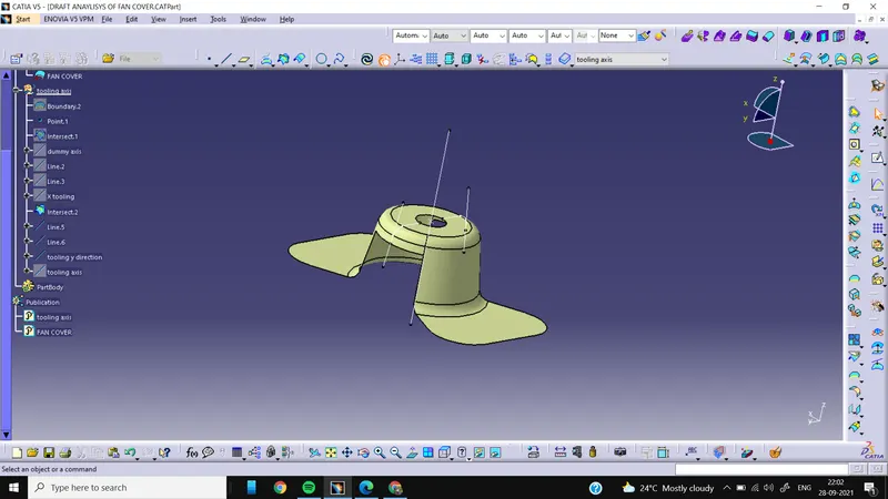
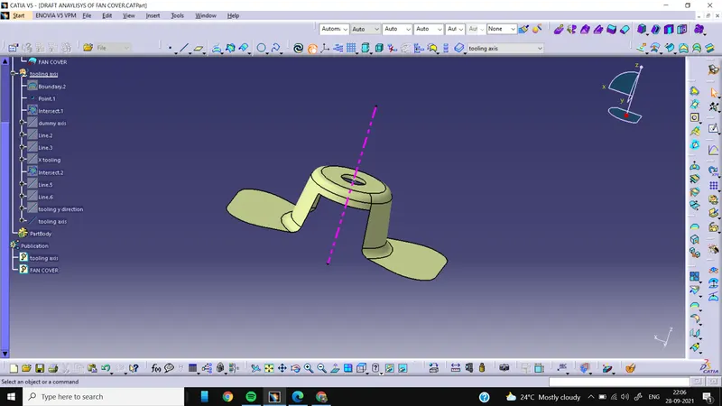
now bisecting both the axis so that we will get our final tooling axis. and then publish it by using publish command
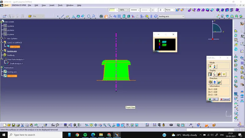
now we have to perform the draft analysis for that first of all we have to align the compass with the tooling axis to define the new current draft direction.
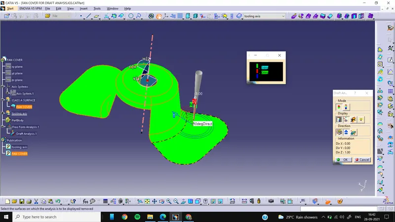
From the color coding above table it is said more than 2.9 is green and less than is red. when we lock the component and click on the running point it will show us a pointer which we can place it anywhere on the model so that it shows the angle with respect to the tooling axis.
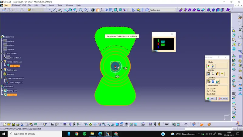
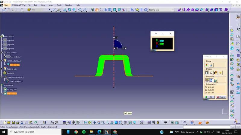
- Green color indicates that the model passed in the draft analysis also it represent the draft angle of 2.9 and above 2.9
- Red color indicates that the model darft angle is zero
- Blue color defines the negative draft angle or less than zero draft angle.
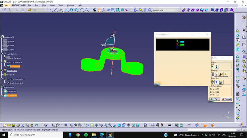
FOLLOWING ARE THE DIFFERENT VIEWS OF ANALYSIS
Isometric view:
top view:
side view:
front view: