Photo Realistic Rendering
Project Report
MODELING OF AMERICAN CHOPPER ON SOLIDWORKS
Index
- Introduction
- Design Approach
- Features
- Modelling of parts
- Assembly
- Rendering
- Special Mention
Introduction
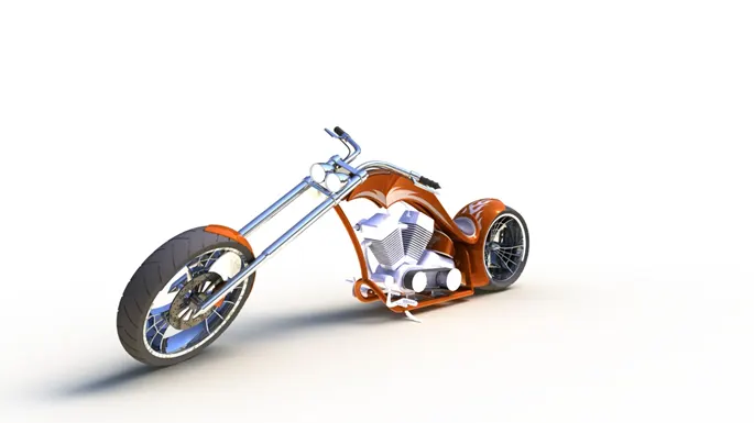
This project is all about modelling of different parts of American chopper bike and then assembling all the parts to make a great looking machine. Also this project contains rendering and photo view 360, which gives us a realistic and natural view and it comes so natural that it just treat to our eyes after this all hard work.
Design approach
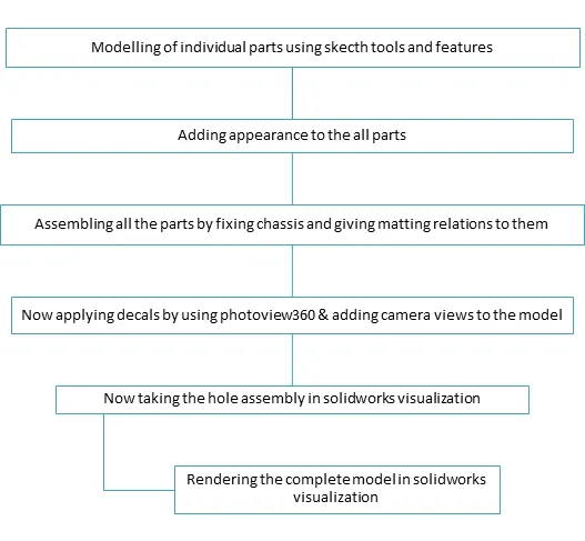
For every modelling design there are two approaches one is top to bottom approach and other is bottom to top approach for this assembly we are using bottom to top approach. Design is starts with the modelling of engine component like transmission belt and then components which are attached with the body frame like fenders kick stand etc. following flow chart shows all the information about each and every step.
Features
Features Plays an important role in solidworks modelling it helps to make different shapes, cuts on surfaces and on solid bodies. Let us discuss all the features which we have used in modelling of this chopper
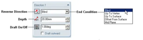
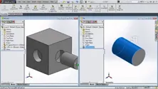
- Extrude Boss/Base: An Extruded Boss/Base feature will allow you to take a 2D sketch and add thickness to it in the third dimension. Every few releases, this feature gets some terrific functionality added to it. To perform extrude we shouldn’t forget to give the accurate directions like from blind or up to the surface or mid points etc.
- Fillet: Fillet/Round creates a rounded internal or external face on the part. You can fillet all edges of a face, selected sets of faces, selected edges, or edge loops. We can use different types of fillets according to shape of our model Such as Round fillet, constant radius, multiple radius.
|
|
|
|
|
|
|
|


- Revolved Boss/Base:
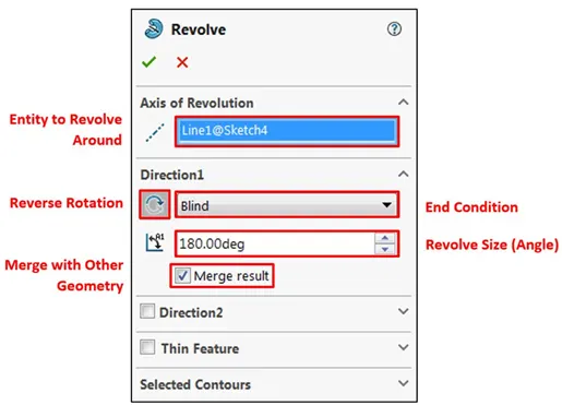
Revolved Boss or Base is a SolidWorks feature tool which is used to create solid 3D model around an axis. You can revolve the sketch around an axis to add materials to it.
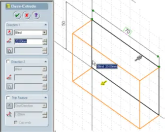
- Extrude Cut: Extrude tool is used to extend a sketched profile in one or two directions as either a thin feature or a solid feature. An extrude operation can either add material to a part (in a base or boss) or remove material from a part.
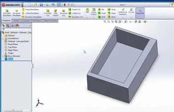
- Shell: The shell tool hollows out a part, leaves open the faces you select, and creates thin-walled features on the remaining faces. If you do not select any face on the model, you can shell a solid part, creating a closed, hollow model. You can also shell a model using multiple thicknesses.
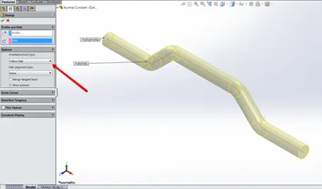
- Sweep Boss / Sweep Cut: Solidworks swept cut is features tool, mainly used to cut a solid model or part by sweeping a completely closed profile along an open or closed path. To use swept cut, you should need a closed profile and open or closed path, which may be line, helix, and circle, rectangular or arc etc.
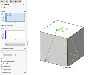
- Loft Boss/ Loft Cut: A lofted cut is a feature that removes material between two sketch profiles. To complete a lofted cut, you must create a minimum of two separate sketches on your part that you wish to cut between. Once you have created your two sketches, you are ready to cut.
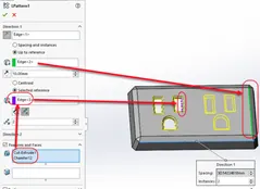
- Linear Pattern: A linear number pattern is a sequence of numbers whose difference between all the terms is the same. You can use linear patterns to create multiple instances of one or more features that you can space uniformly along one or two linear paths.
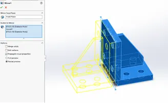
- Mirror: The ability to mirror can be found in part and assembly files, and allows you to mirror sketch entities, features, faces, bodies, and components. Creates a copy of a feature, (or multiple features), mirrored about a face or a plane. You can select the feature or you can select the faces that comprise the feature. Bodies to Mirror. Select a body in a single model or multibody part to create a mirror entity.
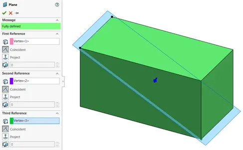
- Reference Geometry: Reference geometry defines the shape or form of a surface or a solid. Reference geometry includes items such as planes, axes, coordinate systems, and points. You can use reference geometry in the creation of several kinds of features.
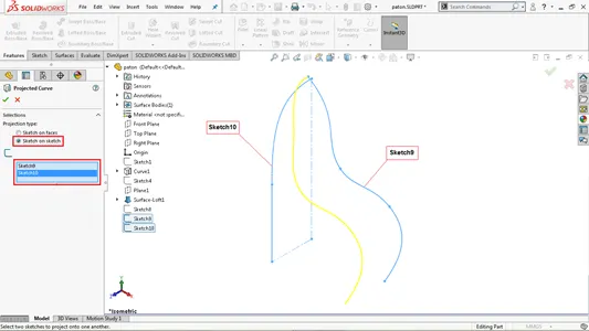
- Projected Curve: You can project a sketched curve onto a model face to create a 3D curve. You can also create a 3D curve that represents the intersection of two extruded surfaces generated by creating sketches on two intersecting planes.You can create multiple closed or open-contour projected curves from a single sketch. You can also use 3D sketches as input for the Projected Curve tool. The Projected Curve tool does not support projections of intersecting curves.
- Mates: Mates create geometric relationships between assembly components. As you add mates, you define the allowable directions of linear or rotational motion of the components. You can move a component within its degrees of freedom, visualizing the assembly's behaviour. Mates are solved together as a system. The order in which you add mates does not matter; all mates are solved at the same time. You can suppress mates just as you can suppress features.
Modelling of parts
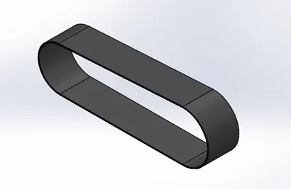
1.Transmission Belt: It is the most important part of engine. It is used to transmit relative power of motors and it is modelled by simple boss extrude feature to make solid belt later some fillets are applied which gives a round edge and later appearance is gives as matt rubber.
2.Kickstand: When the bike is at rest or in ideal position all the weight of bike is on the kick stand so the contact of kick stand with the ground must be flat so split tool is used to make it and then some domes are also applied to both the ends to give a circular shape and extrude boss/base is used to make the part later on fillets are used to make it smooth and it also gives a nice shape.
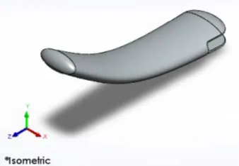
3.Front fender: Fender is used to protect the rider from the stones, dirt which are being thrown by the tyre in the air here it has been modelled by using revolving the planes and axis and then extra part is removed by split tool to give a desired shape then fillets are applied to make edges smooth and then appearance on face or siena colour is applied which gives it same appearance as to the remaining part.
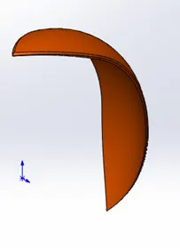
4.Rear fender: Rear fender is modelled with the same method which we have used for front fender just the difference is between the sizes of both fenders and also it has same appearance as of that front fender.
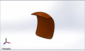
5.Chain: Chain transfers the power from engine to rotor of rear wheel which results in the motion of vehicle. In this part we have first sketched the path by then we have created two chain blocks which are used to make the pattern of upper part then again we used same blocks and we have to give the directions according to the curve when one side of the total chain is done then we used the mirror function. A fine finished chrome plate metal is used as the appearance of the linked part.
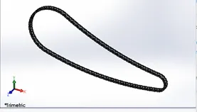
6.Oil tank: since the oil tank is positioned on the engine the bottom surface is made flat on the top plane and it has been adjusted with the height such that it should not coincide with chassis. The shell feature plays an important role in the making of oil tank shell feature gives that hollow shape from inside without affecting outer shape later siena appearance has been applied for nice looks .
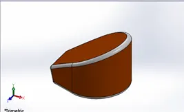
7.Pedals: Pedals are strong rigid body and it is also one of the most used part of any bike so the basic modelling is begin with front plane and then extrude boss/base is used to make a solid body and then three more extrude bosses are used to make a foot resting part then fine chrome finish appearance is applied which matches with the appearance of kick stand.
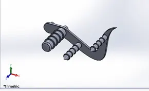
- Front wheel/ Rear wheel: Both the front wheel and Rear wheel has almost same designing methods just the difference is between the width and diameter of both tyres. First of all the rims are designed with the help of revolve feature then spoke is created which then used to make circular pattern to make similar spoke then rotor is designed used extrude boss/base and then callipers are designed then the tyre is designed using revolve feature. Then treads are applied on the tyre and some fillets are used in treads to make round shaped treads. The rear tyre also contains chain sprocket so it is created with the help of extrude boss/base and then extra part is removed with the help of extrude cut and circular pattern. Finally The entire wheel consists of five solid parts Chrome finished Rims, Sienna metal painted Caliper, Chrome finished sprocket and matte rubber tires.
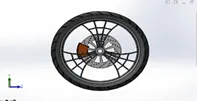
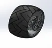
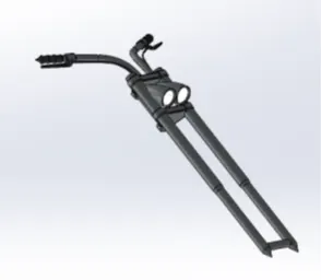
9.Front fork: Front fork gives the desired direction to the bike it is attached with the chassis at triple clamps also the front tyre and front fender is also attached to the front fork so it has been designed with the help of extrude boss/base firstly we just designed the right side which contains the handle bar for which we have used swept boss base feature and then we designed the headlight and shell feature gives the desired shell to headlights. And then the right side is mirrored against the triple clamp and at last the rubber appearance is given to the handle grips and the break wire and chrome plate appearance is given to entire forks and lighting appearance is given to headlights.
10.Chassis: All designed parts are mounted on the chassis it is first part which is fixed while assembly it is designed with the help of sketch and then extrude boss base feature is used to make solid body parts of it two projected curves gives the lower curved path and swept boss/base is used to make solid profiles of rear wheel and split tool is also used to remove extra portion of the rods which connects the front shell to join the chassis with the front fork a revolve part is created at the front and other the joints between the two sweeped rods is extruded, now to make the attachments with the pedals and the kick stand two geometries are created extruded and the undesired part is extruded out. At the end all the sharp edges undergo desired fillet and a plane is added for the purpose of the further assembly purposes. also the chassis has the same Siena appearance to match with other parts.
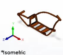
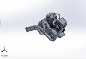
11.Engine: Engine contains motors, exhaust pipes spark plugs it is the most complex design of any bike while the designing firstly both the motors are designed with extrude feature and then extrude cut is used to give cut and fillets are used to make teeth on the wheel and then teeth is copied with the help of circular pattern part is created so that transmission belt will smoothly run over the part later on the curved part of engine is created with the help of extrude cut and then top case is created with extrude boss base and then it is mirrored about construction line and then exhaust pipes are designed with the help of projection curves at last the air intake is designed with swept boss/base feature and then extra part is removed with extrude cut and then the cut is patterned with the help of circular pattern which connects with exhaust pipes and then by using extrudes we have designed the spark plugs at the top and later on appearance has been added to engine and all other parts.
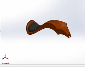
12.Gas tank: Gas tank covers the engine and oil tank also it prevents the rider from heat of engine also gas tank includes the seat firstly the one side of gas in created which takes additional reference and surface sweep is used to attain the basic layout of the gas tank, now the edge is surface trimmed to attain the design of the tank one more plane is added and a surface loft is created as the front face of the tank now with the help of boundary sweep feature the front face and the side face are joined together with the rear of the gas tank now mirroring the entire part and knitting them together we get the entire gas tank structure.
Assembly
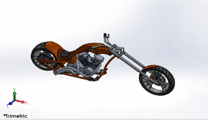
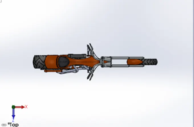
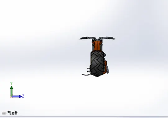
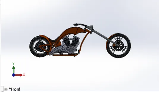
After modelling of all parts is done assembly is the only thing which brings all the part together and gives us a desired machine for which we are working for firstly we have to open a solidworks assembly and then we have to insert all the components for this chopper assembly we are fixing the chassis first then we use the planes of chassis to relate with the planes of remaining parts. Firstly we bring the engine and give coincident mate to the base of engine with the plates of chassis and we also give distance mate for the base of engine and plate of chassis after the fixing of engine we bring the pedals it has round pins which will be coincident with the holes of chassis and then same pedal is mirrored to the other side, now we bring in the kick stand here first mate made is a concentric with the hole created in the chassis and the extruded part in the stand the to define the angular rotation of the kick stand an angular mate is provided with the body so that it will move to desired angle only then we bring the transmission belt it has coincident mate with the rotor teeth then we bring oil tank which have coincident mate with the curve part of engine and then rear wheel is taken and it has coincident mate with the chassis and then we bring the rear fender and it has coincident mate with the rear wheel and then finally front fork is taken and the front fork is mated coincidently with the upper part of the chassis and a width mate is applied to retain the vertical motion of the fork now for the turning angle of the front part of the chopper an angle mate with certain limitations is applied with the fork and the chassis then then front wheel and front wheel is attached to it front fender has a coincident mate with the wheel and front wheel has coincident mate with the front fork
Rendering
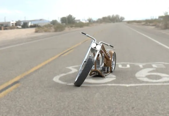
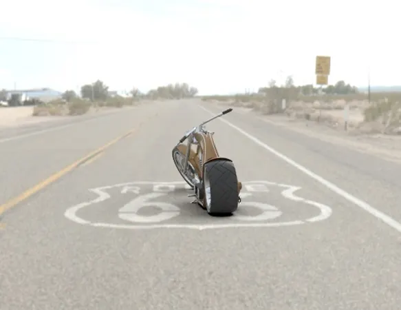
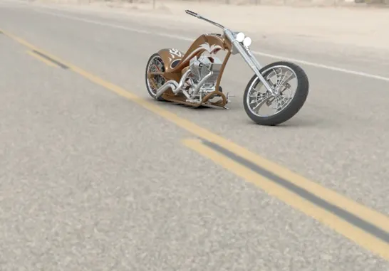
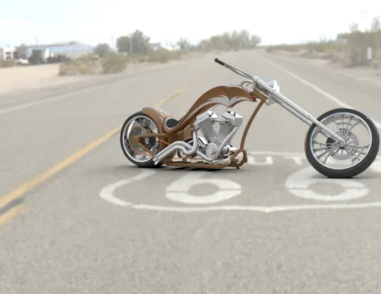
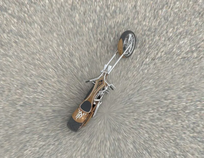
Rendering gives our chopper a realistic and natural look. But before rendering some decals are added to some bodies our chopper with the help of photoview360 on both fenders, gas tank and also oil tank which brings a better look to our chopper. Now we try to make it more realistic by giving it a camera view setting the desired lights and the focal distance creating the angle of the view and saving the camera angle which gave a realistic view to the chopper. We also bring camera view for our chopper later on we took our decals added chopper assembly to solidworks visualize where we adjusted the brightness of color of chopper and camera views of our bike and then we added background of iconic route66 environment and then by adjusting gamma value and shadows and positioning we started rendering and got realistic outcomes.
Special thanks
I am highly indebted to Abhiteja Padma and all other faculties of skill-lync for their guidance and constant supervision as well as for providing necessary information regarding the project & also for their support in completing the project.
Thank you.