Week 8 - Challenge 2 - Base Bracket Design
OBJECTIVE:
Creating the Base Bracket Plastic component through the given Class-A surface.
Class A surface:
It is the visible aesthetic surface which have curvature and tangency alignment to ideal aesthetical reflection quality of any automotive component. Class A surface refers to those surfaces which are visible It is a required where aesthetics has a significant contribution.
Class B surface:
It is a surface which is offset below a certain thickness from the class A surface. All the features of the product are to be performed on the class B surface with respect to class A surface
Class C surface:
class c surface is the surface which is used to join both the Class A and Class B. This surface connects both A and B surfaces along the Tooling Axis. It contains the draft as per the design. It is basically the thickened surface between both A and B surface
PROCEDURE:
- First ensure the class-A surface is properly joined and has no discontinuity on it. For this we can use boundary command or join command.
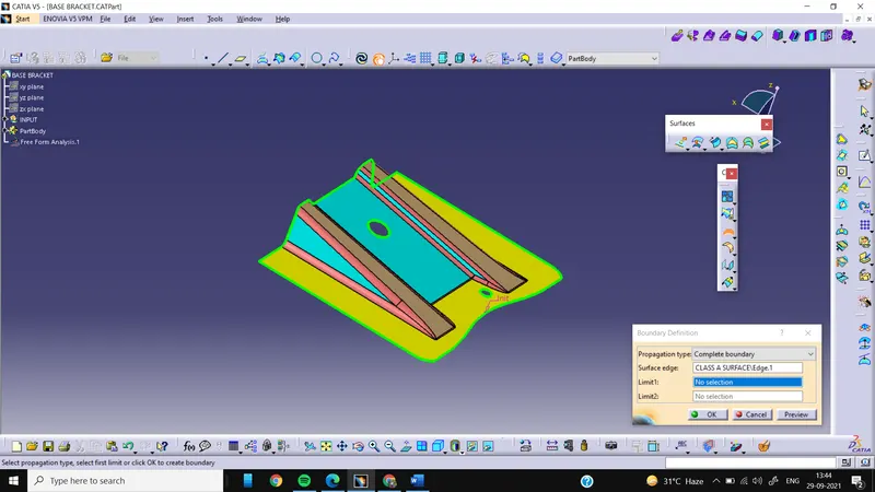
- Analysis the model manually or visually to see which direction is most suitable for tooling axis.
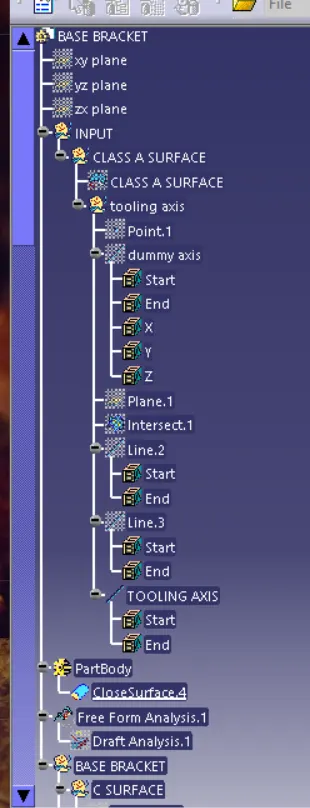
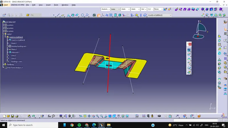
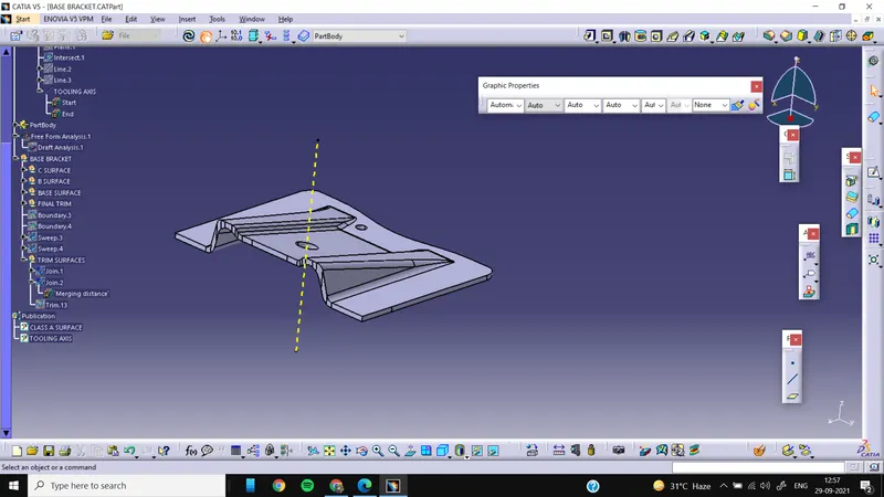
- Now we need to create the tooling axis for the base bracket model. Visually check which direction is better for creating tooling axis. First create a dummy tooling axis in Z direction.
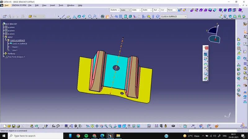
above line 1 is dummy tool axis
- Now create the YZ plane at the centre point of the hole (reference point).
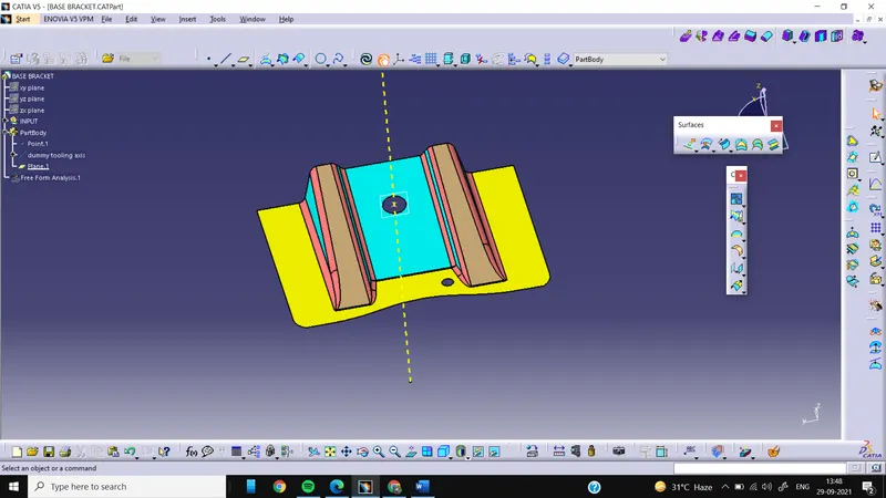
- Now using the intersect option, select the YZ plane as first element and base bracket (Class A surface) as second element. This will give a 2D sketch of fan cover viewing from Y-direction.
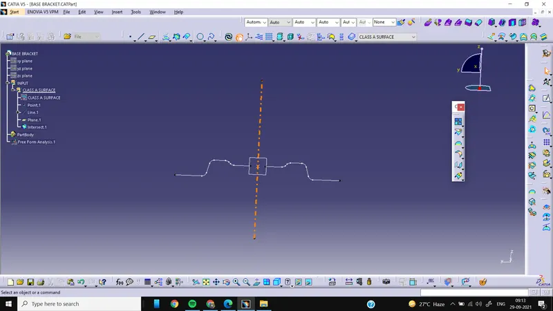
- Now create lines through the walls of a base bracket using point to point option with the help of intersect 1 where you think the tooling might create problem. And using these 2 lines create a bisecting line from reference point in Z direction. This will form a main tooling axis in Z direction
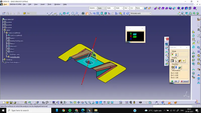
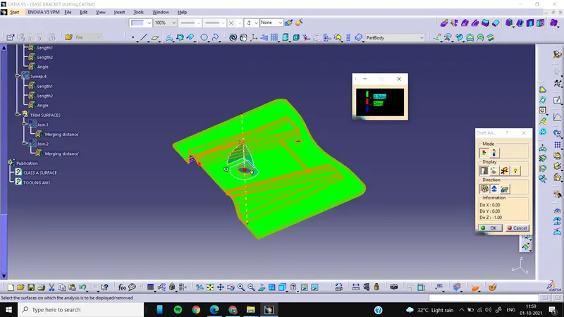
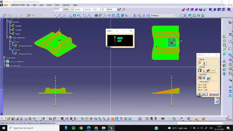
- go for draft analysis and use compass for draft direction and select the tooling axis
- The green colour in this analysis shows that our model is passed in the analysis and also indicated the drafting angle 2.9 deg and above 2.9 deg.
- Red color indicates the angle 0 degree draft angle.
- and blue color indicates the negative draft angle.
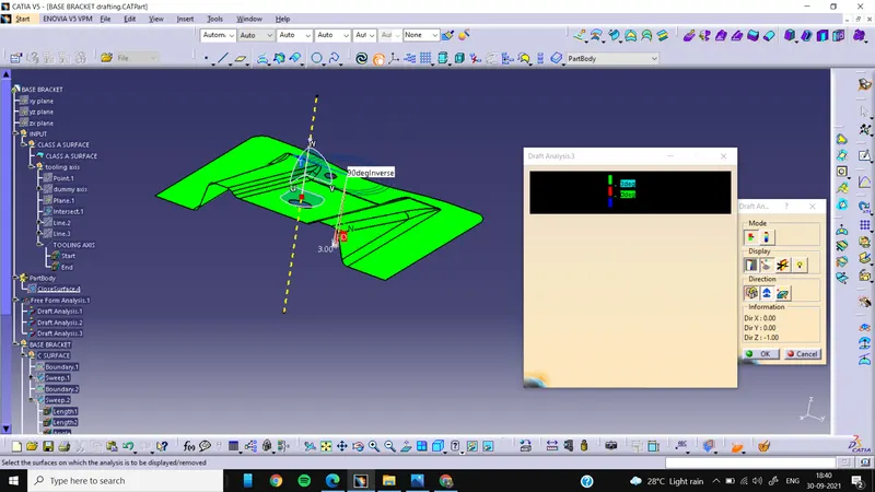
- Lock the surface and analysis the running point
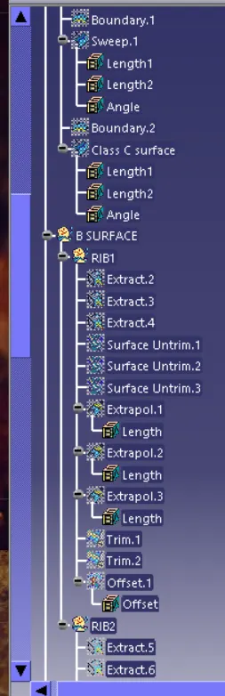
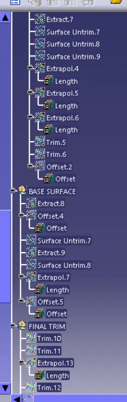
- After that we have to create class B surface for that we need to extract the different surfaces of class A then we have to untrim it and then we have to extrapolate the surface and then using the trim tool we have to trim extrapolated surface to get required design.
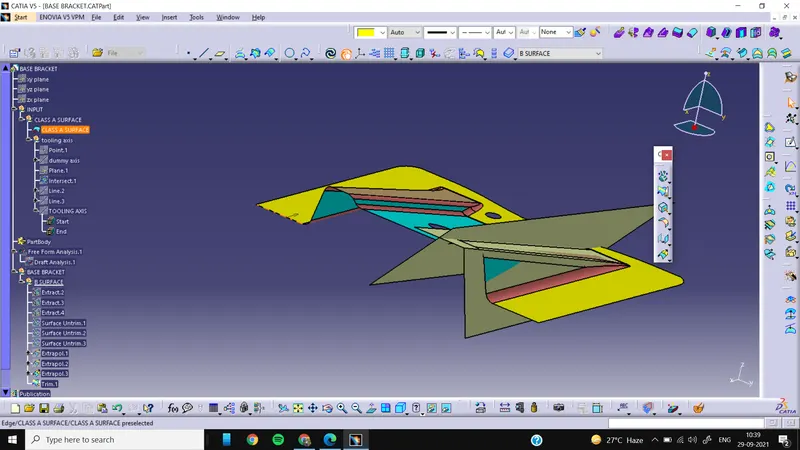
- Now offset the obtained trim for the thickness of 2.5mm
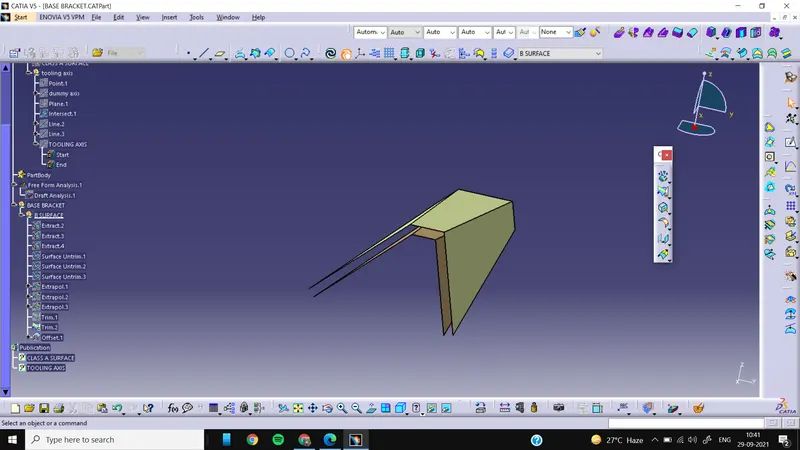
Perform the same procedure for the next surface and middle portion also
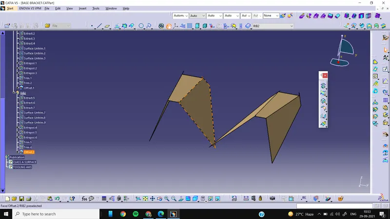
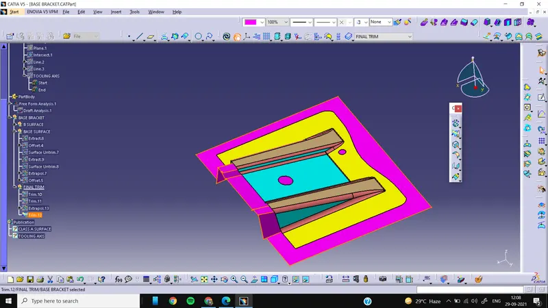
- Then apply the edge fillets as per required
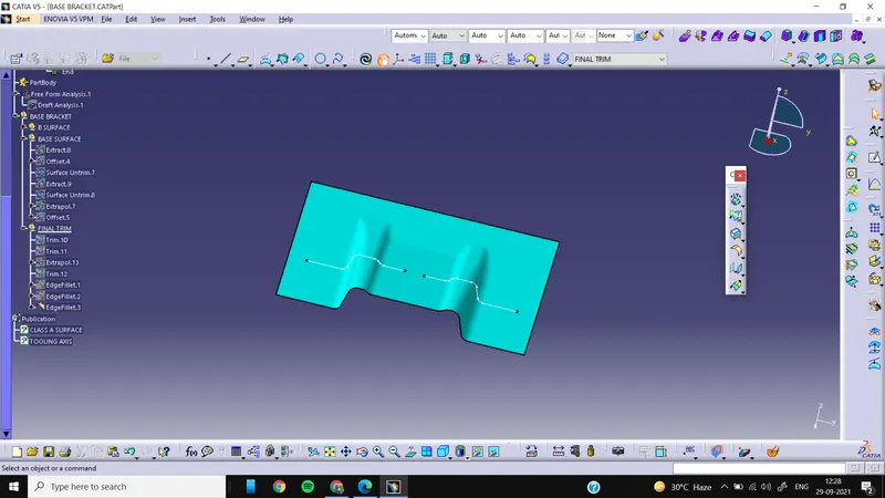
- Create boundary for class a surface and also for holes and
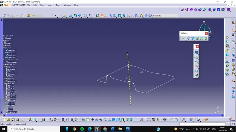
- then draft for 3 degree by using sweep command
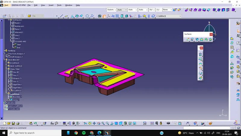
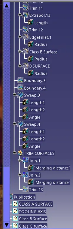
- Then join class A and class c surface using join command and Then trim the joined surface with the Class B surface
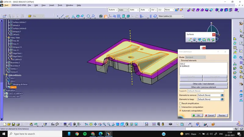
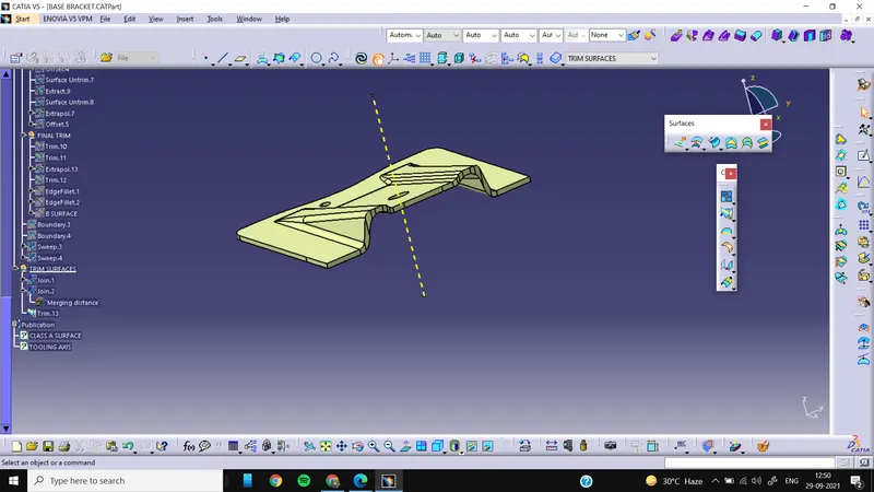
- Then use close surface boundary to make closed surface solid
different views are as follows:
1.ISOMETRIC VIEW:
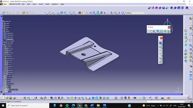
2.FRONT VIEW:
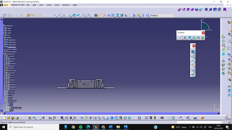
3.SIDE VIEW:
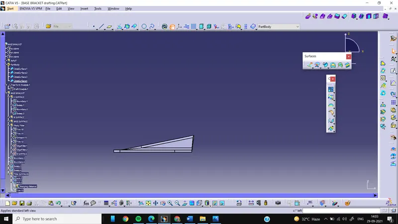
4.TOP VIEW:
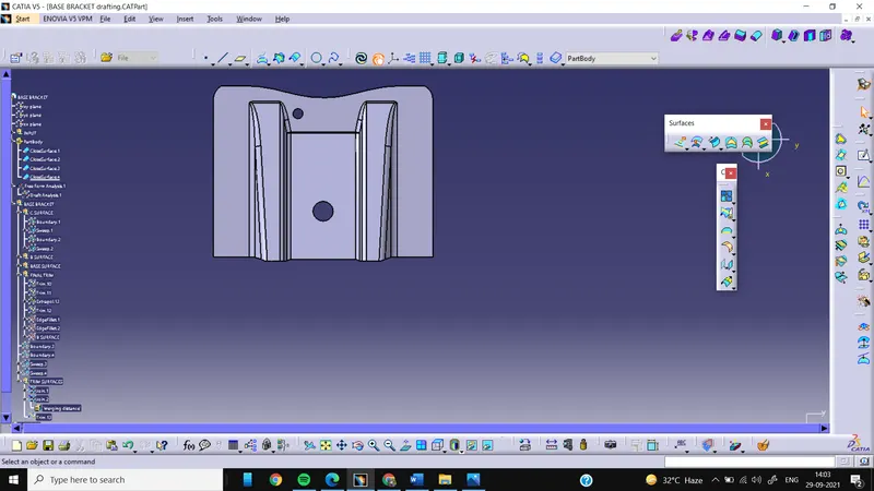
Draft analysis of closed body:
tree structure: