Week 11.1: Turbo Charger Simulation Project
Turbo Charger Simulation Project
- Aim:
To simulate a transient simulation on a turbocharger made-up model and to analyse its impellers speeds on 3 different pressure ratio cases. Also calculate the end time required to obtain max impeller speed once it reaches steady state.
- Theory:
1. Turbo Charger:
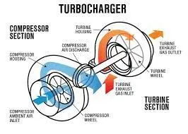
A turbocharger, formally a turbosupercharger and colloquially known as turbo, is a turbine-driven, forced induction device that increases an internal combustion engine's power output by forcing extra compressed air into the combustion chamber. This improvement over a naturally aspirated engine's power output is because the compressor can force more air—and proportionately more fuel—into the combustion chamber than atmospheric pressure (and for that matter, ram air intakes) alone.
- Working:
In naturally aspirated piston engines, intake gases are drawn or "pushed" into the engine by atmospheric pressure filling the volumetric void caused by the downward stroke of the piston (which creates a low-pressure area), similar to drawing liquid using a syringe. The amount of air actually drawn in, compared with the theoretical amount if the engine could maintain atmospheric pressure, is called volumetric efficiency. The objective of a turbocharger is to improve an engine's volumetric efficiency by increasing the pressure of the intake gas (usually air) allowing more power per engine cycle.
- Procedure:
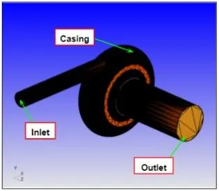
Model was pre-processed and suitable boundary flagging was performed. The scale was reduced to meters from mm.
- Geometry:
- Turbine:
- Case Setup:
1. Application: General flow
2. Solver: Transient solver
3. Simulation type: Gas
4. Simulation time parameters:
start time: 0 sec
end time: 0.006 sec
5. Regions and initialisation:
In this step, we have created a region of the fluid and initialise the species value as follows:
N2= 0.77
O2= 0.23
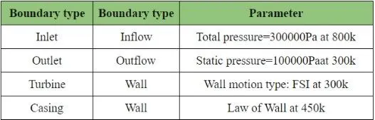
6. Boundary conditions:
7. Physical Models:
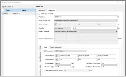
RNG K-epsilon, FSI
- Fluid Structure Interaction:
8. Grid control:
element size: x=y=z=1e-4m
9. Output files:
- 3D files: 6e-5sec
- Text output: 1e-5sec
- Restart files: 6e-5sec
- Max number of restart files saved: 3
- Results:
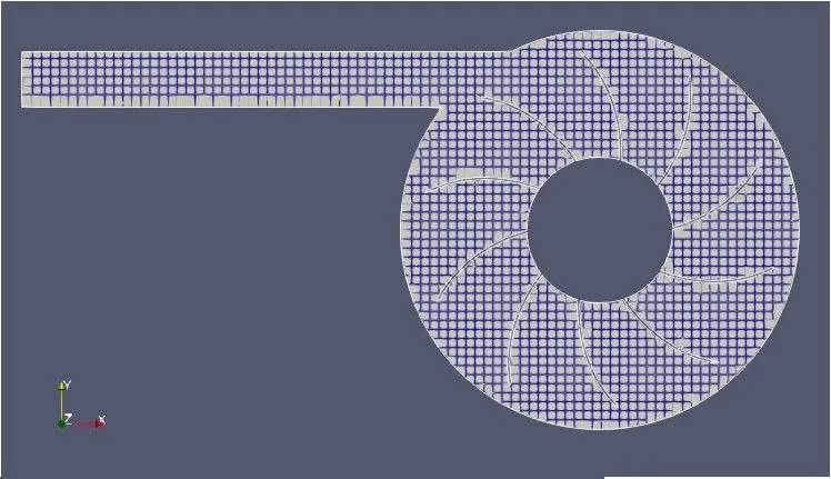
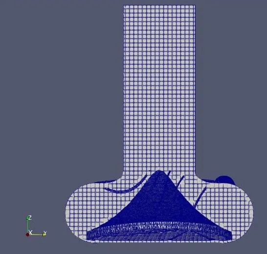
- Mesh:
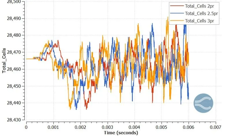
- Total cell count:
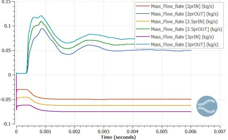
- Mass flow rate:
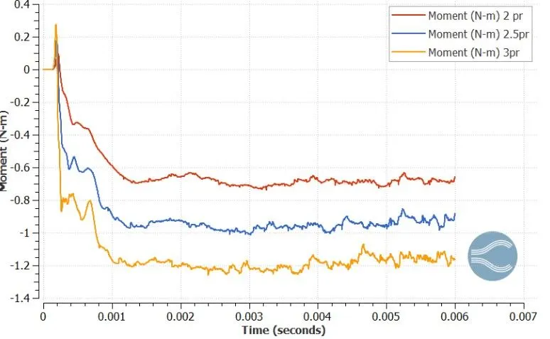
- Torque:
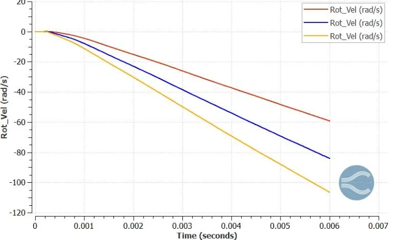
- Rotational velocity:
- Conclusion:
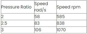
- Speed of impeller/turbine:
- In order to achieve max impeller speed, the simulation is required to run longer until the simulation reaches steady state. Therefore, we need to extend our end time accordingly.
at PR 3 we achieved an impeller speed of 1070 rpm. Now in order to achieve 2000rpm when ran till it reaches steady state is given by,
0.006(2000/1070)= 1.12sec
Therefore, we need to run for 1.12 sec inorder to find out the max speed of impleller.