Week 10 - Simulating Combustion of Natural Gas.
Aim: To perform a combustion simulation on the combuster model using Ansys
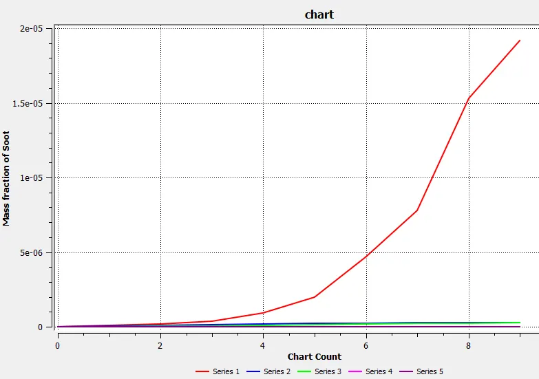
Part 1: Perform a combustion simulation on the combustor model and plot the variation of the mass fraction of the different species’ in the simulation using line probes at different locations of the combustor as shown in Fig. You need to plot for CO2, H2O, CH4, N2, O2, NOx emissions & Soot formation.
Part 2: In this part, you need to add the water content in the fuel from 5% to 30% by mole and observe the effect of it on the results. It is necessary to provide line plots and contours
Combustion: Coombustion is burning of fuel inside a chamber. A chemical reaction in which fuel reacts with oxygen give large amount of heat. IC engines process is different in the combuster, in the inlet high pressure oxygen rich air sent into chamber and there is an inlet for fuel which srpayed at high velocity throgh the nozzle to atomize and high turbulent air mixes with fuel. The cobustion takes place only after proper mixing of air and fuel. combustor are most important for aircraft and rocket propulation. These combustor produce sufficient heat and thrust for air craft or rocket to be moved.
There are two types of combustion
- Internal combustion
- External combustion
Geometry preparation
The given geometry is imported into spaceclaim. The geometry is axi symmetry it can be splitted into a plane an simulation is performed to get better results and reduced computational power and time
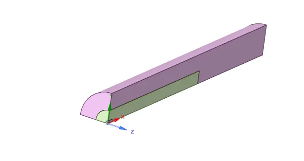
The xy plane is copies and pasted in new design and the earlier geometry is deleted and then combine tool is uesd to combine all the boundaries.

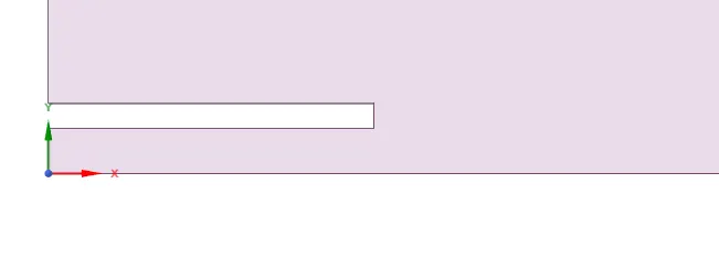
Meshing
Elemet size: 10mm
No of elements: 1777

Setup
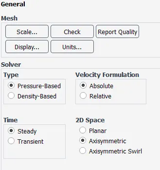
In setup Pressure based solver is used and absulute velocity, steady state time. The 2D space set to axisymmetric
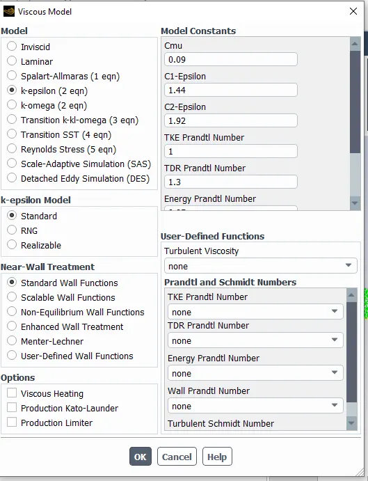
K epsilon model used with standard
Energy turned on as temperature is involved
Species setup
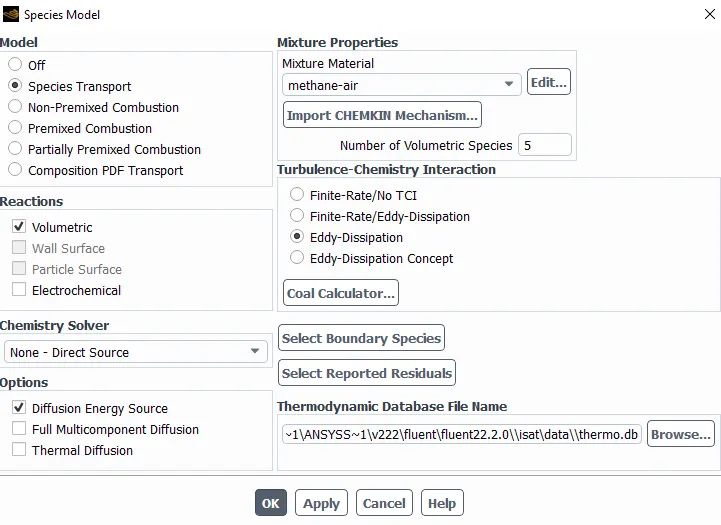
enable species transport and reactions are volumetric, mixture material is methane air selected and enable diffusion energy source and select eddy dissipation
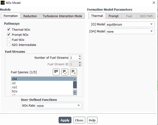
NOx model is selected
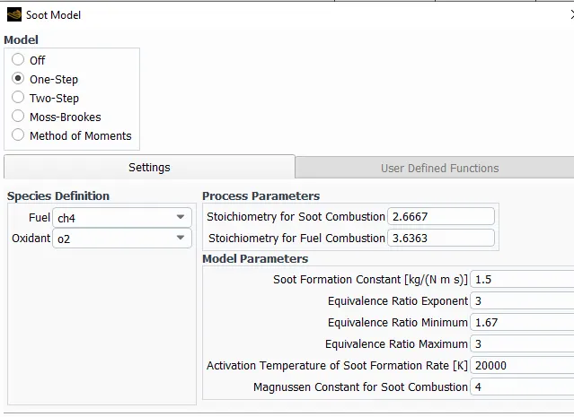
Soot model is also activated
Boundary conditions
Air inlet: velocity=0.5 m/s, mole fraction of o2=0.23
Fuel inlet: Velocity=80m/s, mole fraction of ch4=1
Post processing
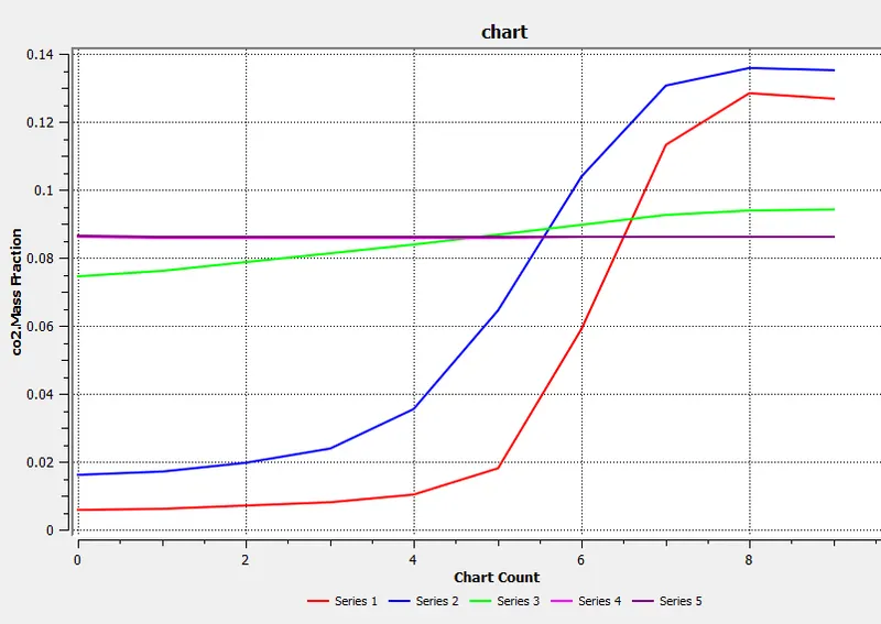
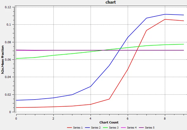
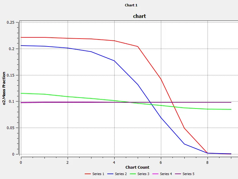
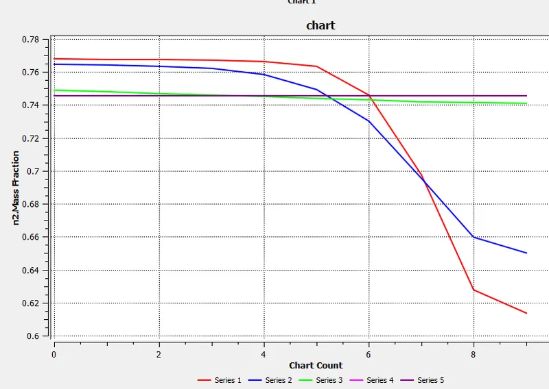
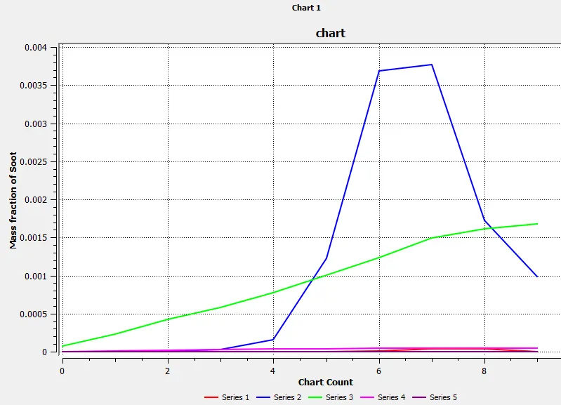
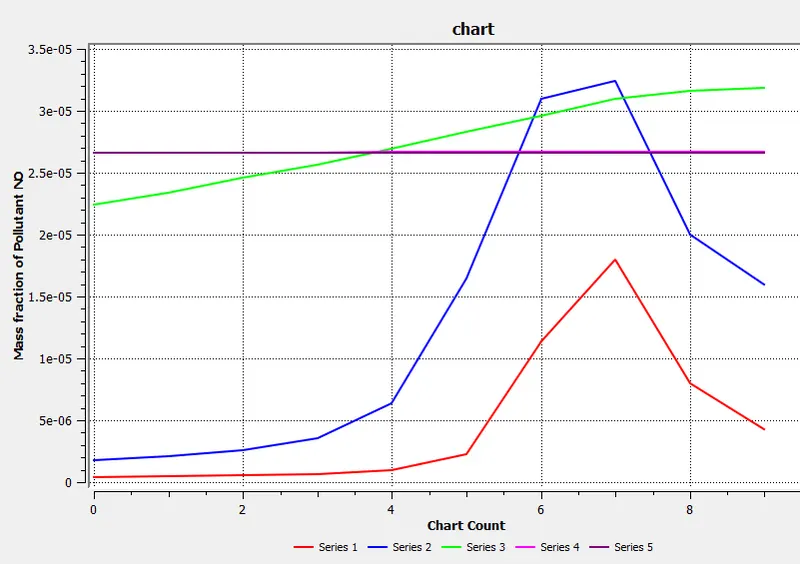
Create line probes at a distance of 0.1, 0.2, 0.3, 0.4, 0.5m
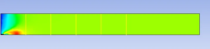
Define contour and plots what we need
Part 1: Without adding water
CH4:1
H20:0
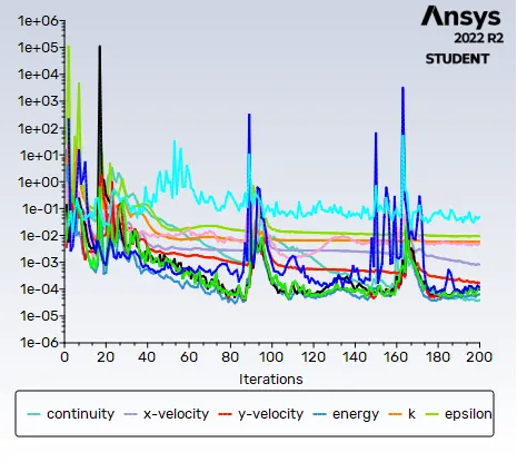
Residuals
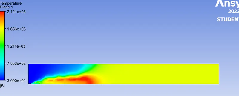
Temperature
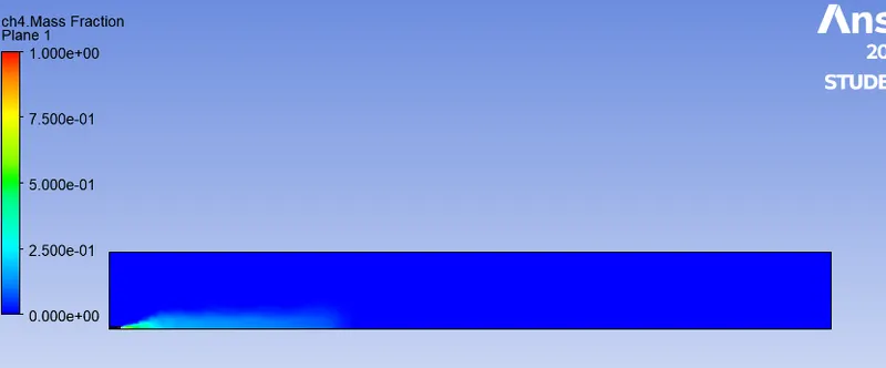
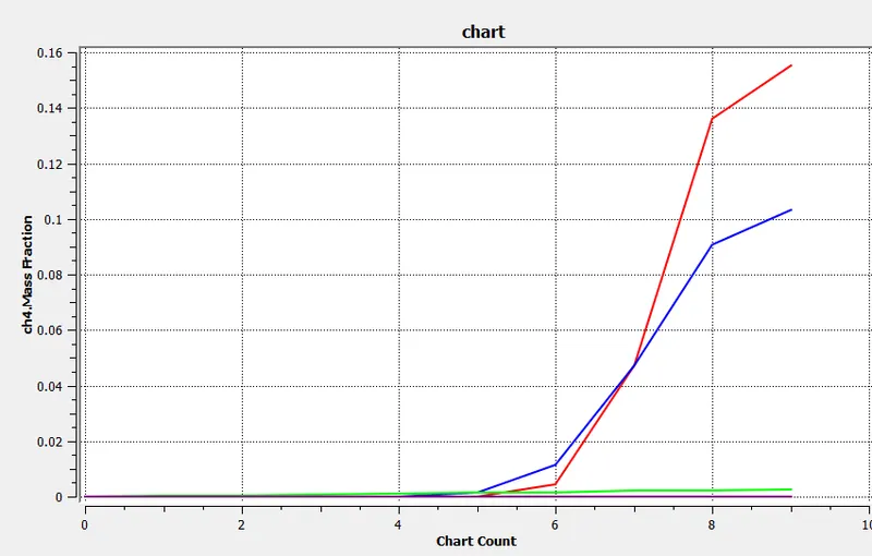
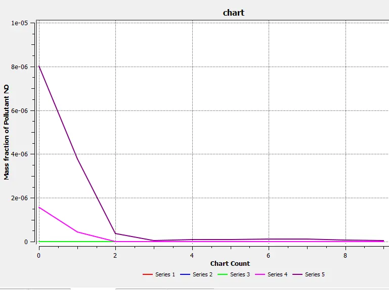
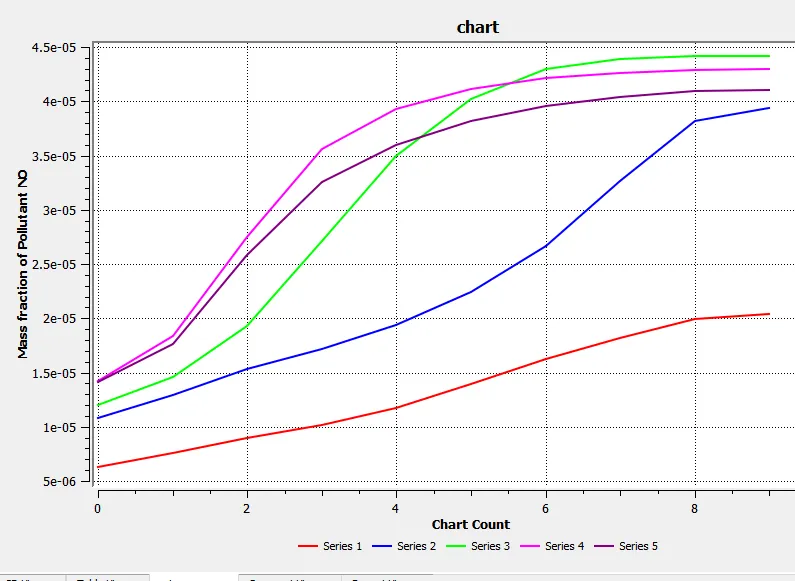
Plots and contours of mass fraction of different species at line probes
Mass fraction of CH4
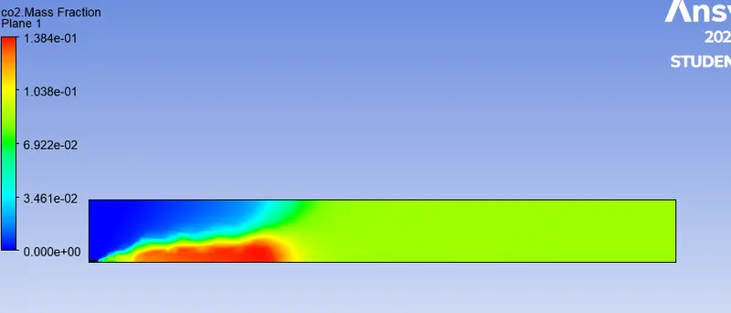
Mass fraction of CO2
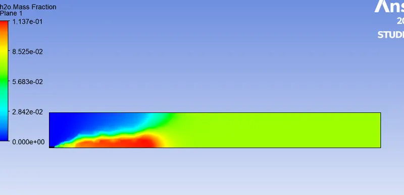
Mass fraction of H2O
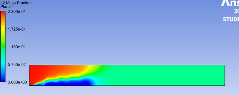
Mass fraction of O2
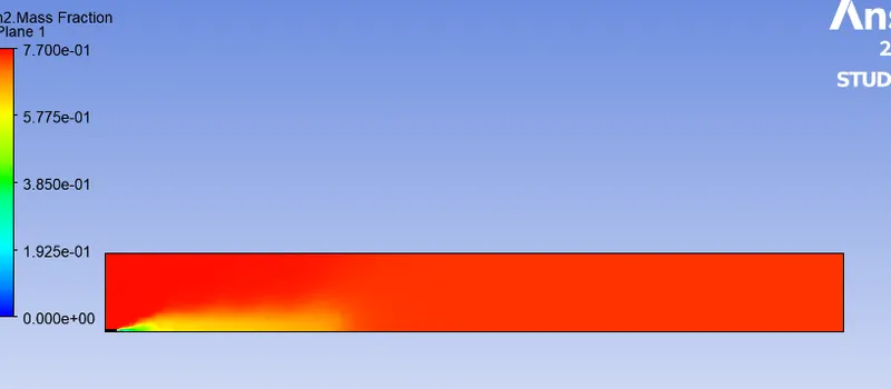
Mass fraction of N2
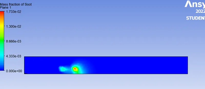
Mass fraction of pollustant Soot
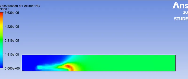
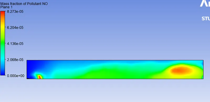
Mass fraction of NOx emmision
Conclusion of part1
Part 2:
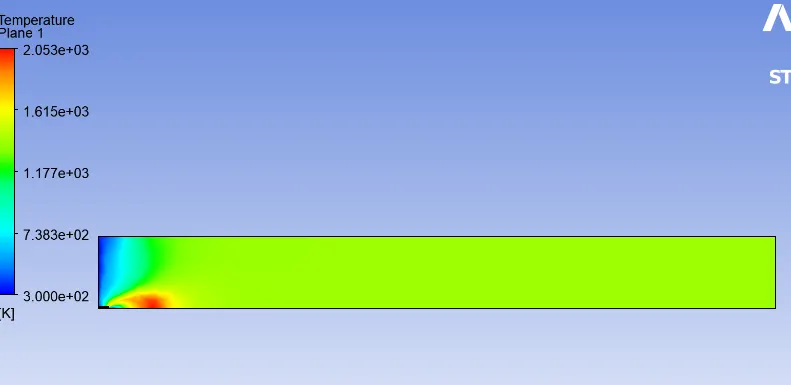
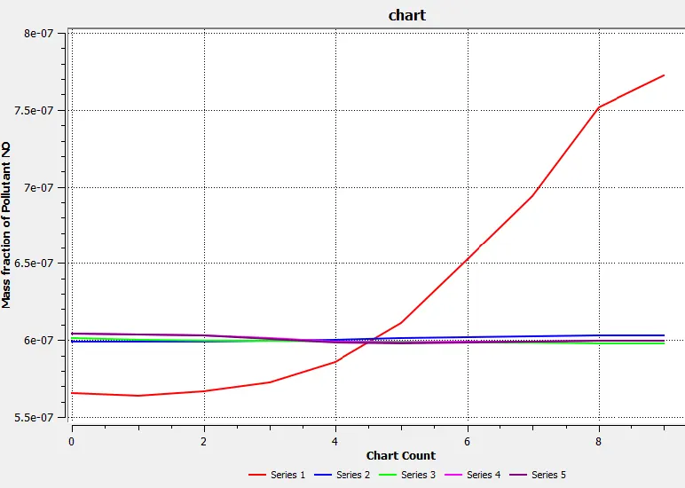
5% water
Temperature contour
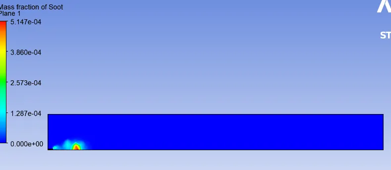
Mass fraction of Soot
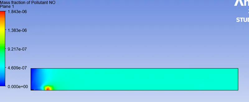
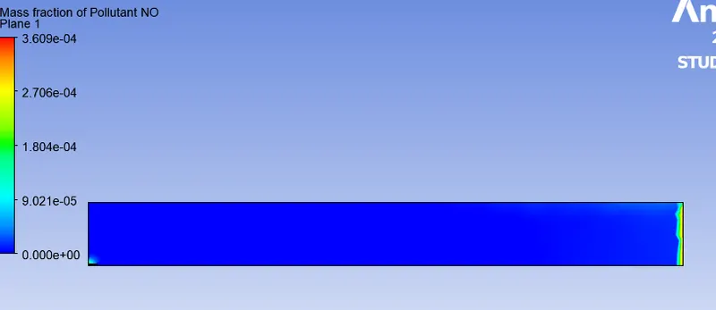
Mass fraction of Pollutant NOx
10% of water
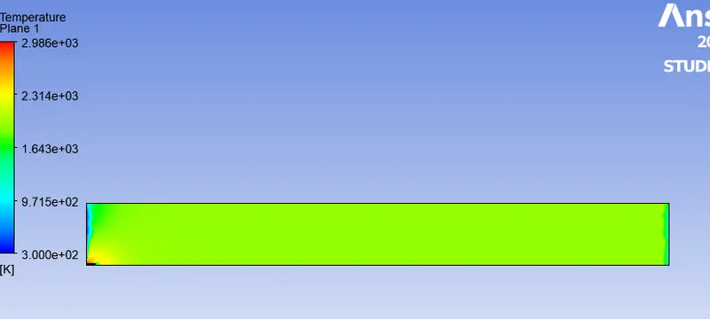
Temperature contour
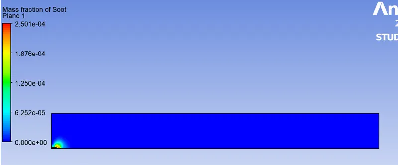
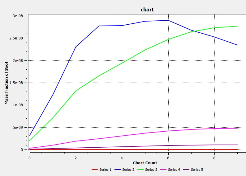
Mass fraction of soot
Mass fraction of NOx
15% of water
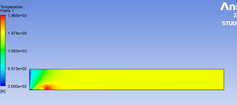
Temperature contour
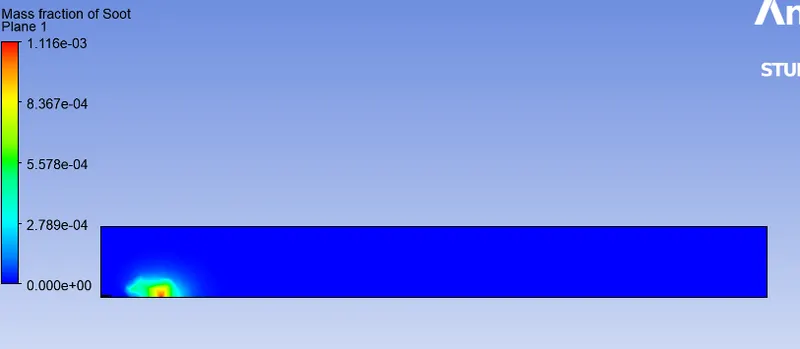
Mass fraction of soot
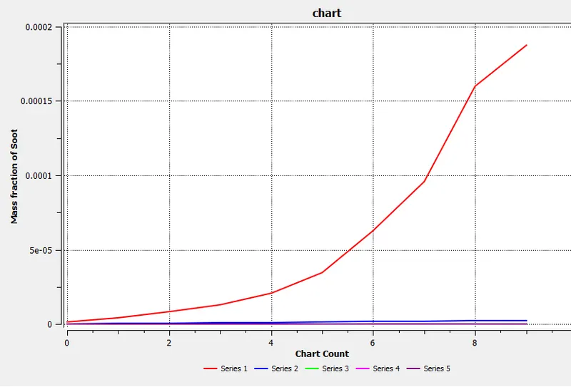
Mass fraction of NOx
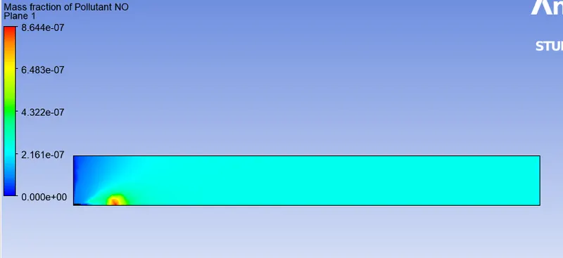
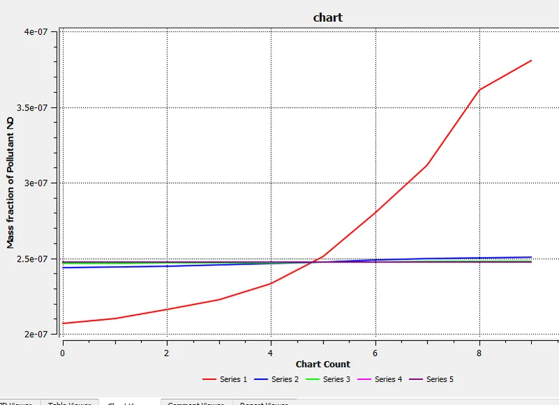
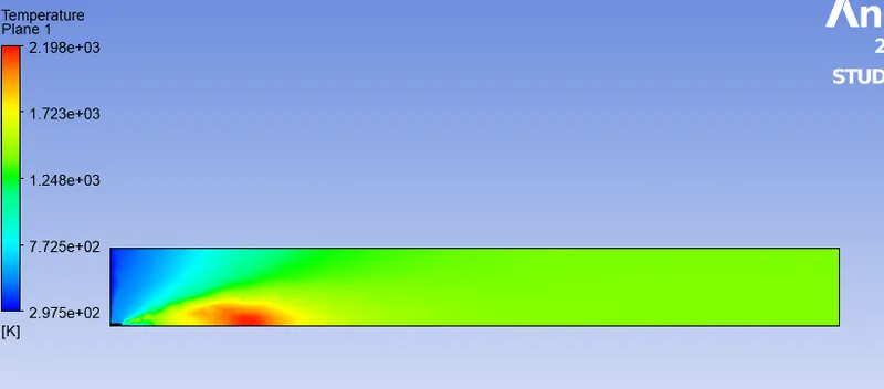
20% of water
Temperature contour
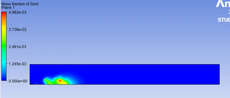
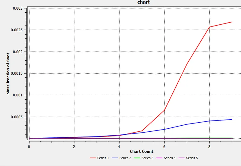
Mass fraction of soot
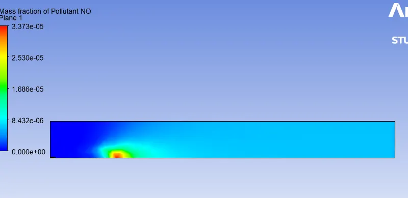
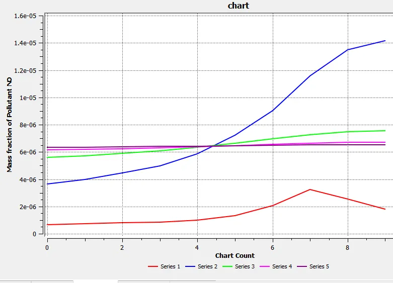
Mass fraction of NOx
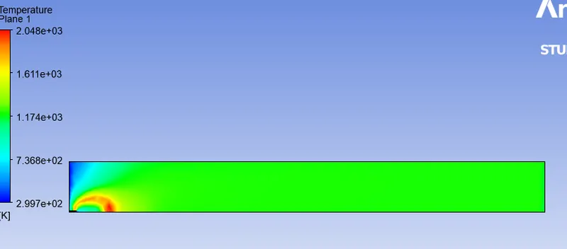
25% of water
Temperature contour
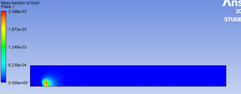
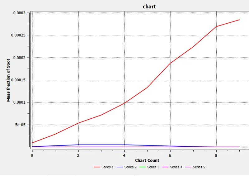
Mass fraction of soot
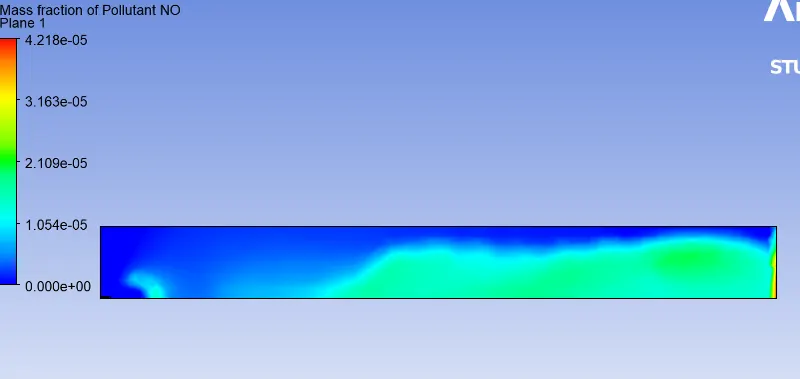
Mass fraction of NOx
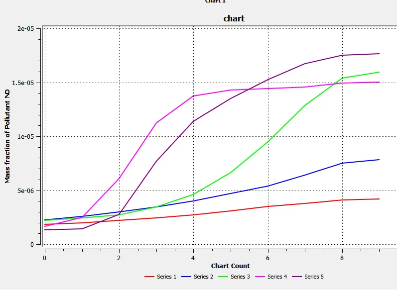
30% of water
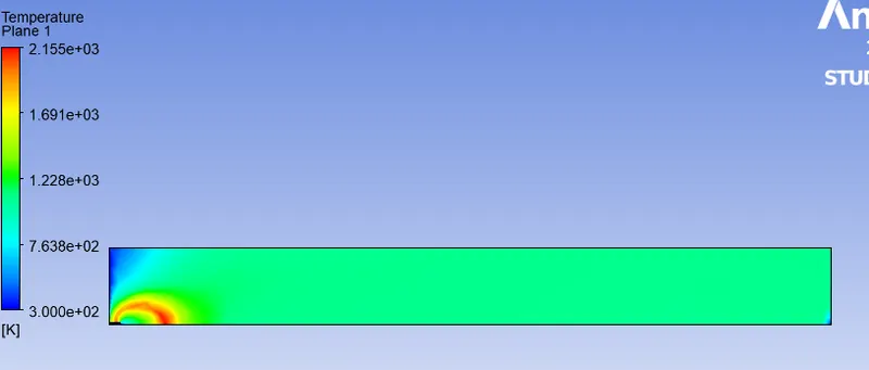
Temperature contour
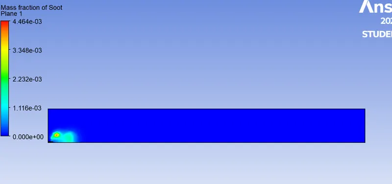
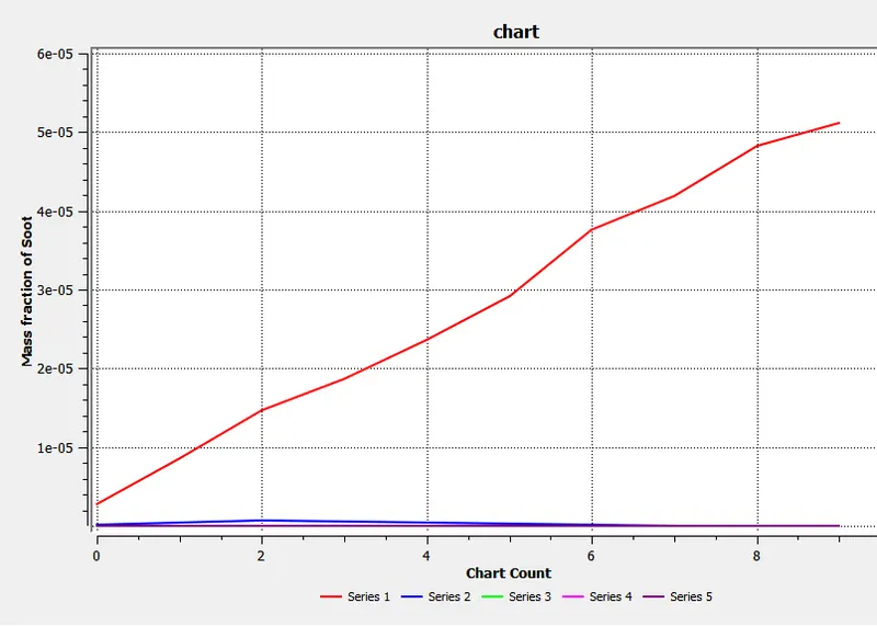
Mass fraction of soot
Mass fraction of NOx
Conclusion
- With the icrease in the mass fraction of water in the fuel- air mixture NOx pollution is reduced
- With the icrease in the mass fraction of water in the fuel- air mixture soot formation is reduced
- With the icrease in the mass fraction of water in the fuel- air mixture efficient of air mixture is achieved
- With the icrease in the mass fraction of water in the fuel- air mixture temperature of exhaust gas is reduced
- With the icrease in the mass fraction of water in the fuel- air mixture velocity of the exhaust gas is reduced
- Succesfully performed simulation on combustor and results are shown