Week 10 - Simulating Combustion of Natural Gas.
Simulating Combustion of Natural Gas
Aim:To perform a combustion simulation on a given combustor model and to observe the variation of mass fraction of different species in the simulation.
Objectives:
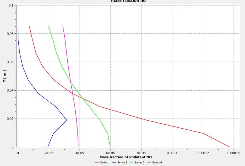
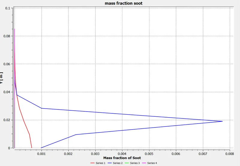
- To perform a combustion simulation on the combustor model and plot the variation of the mass fraction of the different species’ in the simulation using line probes at different locations of the combustor( plot for CO2, H2O, CH4, N2, O2, NOx emissions & Soot formation).
- To check the effect of adding the water( 5% to 30% by mole ) in the fuel in relation with the Nox and soot formation.
Introduction :
Combustion is defined as a chemical reaction in which a hydrocarbon fuel reacts with an oxidant to form products, accompanied by the release of energy in the form of heat. Being an integral part of various engineering applications like internal combustion engines, furnaces, and power station combustors, combustion exhibits itself as a wide domain during the design, analysis, and performance characteristics stages of the above-mentioned applications. To solve the complex equations from chemical kinetics and to yield information about the reaction mechanism, proper physical modeling has to be done. In this project, the combustion process is simulated with the help of CFD software ANSYS fluent. When the combustion is incomplete, various pollutants are formed, some pollutants are carbon dioxide, carbon monoxide, lead, and nitric oxide. In this project, the formation of pollutants from NOx emission which mainly consists of No, No2, N2o, and soot formation which is a mass of impure carbon particles are simulated and the variation of mass fraction of pollutants from NOx emission and soot formation with the addition of water into the fuel in studied.
Theory:
Comptational fluid dynamics modeling of combustion calls upon the proper selection and implementation of model suitable to faithfully represent the complex physical and chemical phenomenon associated with any combustion process.
The model should be competent enough to deliver information related to the species concentration, theri volumetric generation or destruction rate and changes in the parameters of the system like enthalpy, temperature and mixture density.
The model should be capable of solving the general transport equations for fluid flow and heat transfer as well as additional equations of combustion chemistry and chemical kinetics incorporated into that as per the simulating environment desired.
Possible types of Combustion Simulation possible in Ansys Fluent
The simulation of combustion can be divided into two types-
A. Combustion based on Mixing
- Non-Premixed Combustion
- In non-premixed combustion, fuel and oxidizer enter the reaction zone in distinct streams.
- It occours during direct injection or late injection of fuel in IC engines.
- Examples of non-premixedcombustion includes pulvarized coal furnaces, diesel internal-combustion engines and pool fires.
- Premixed Combustion
- In premixed combustion,fuel and oxidizer are mixed at the molecular level prior to ignition.
- Combustion occurs as flames front propagating into the unburnt reactants.
- Examples of premixed combustion include aspirated internal combustion engines, lean- premixed gas turbine combustors, and gas-leak explosions.
- Partially Premixed Combustion
- Partially premixed combustion systems are premixed flames with non-uniform fuel-oxidizer mixtures(equivalence ratios).
- Such falmes include premixed jets discharging into an inert atmosphere, lean premixed combustors with difussion pilot fames and cooling air jets, and imperfectly mixed inlets.
B. Combustion based on Phase
- Fluid Phase (Volumetric Reactions)
- Combustion takes place in the fluid region.
- Wall (Surface Reactions)
- Combustion takes place on the wall or a solid surface.
- Particles ( Surface Reactions)
- Combustion takes place on the Lagrangian particles.
- Combustion of coal is an example of particle combustion.
- Porous Region
- Combustion takes place in a porous region.
- The reactions in an after-treatment system is am example of combustion in the porous regions.
The chemical reaction involved in the combustion of methane in air is shown below:
`CH_4 + ar(O_2+3.76*N_2) -> a*CO_2 + b*H_2O + c*N_2`
Where,
1= a,
4 = 2b therefore b=2,
2 ar = 2a+b therefore ar = 2,
ar*7.52=2C therefore C =7.52.
Air has 2 moles of oxygen + 7.52 moles of nitrogen
Mole fraction = Moles of the substance/Total moles of the mixture.
- Mole fraction of Oxygen = 2/9.52 = 0.21
- Mole fraction of Nitrogen = 7.52/9.52 = 0.79
Mass fraction:
Mass fraction = Mass of the substance / Total mass of the mixture
Mass fraction of Oxygen = (16*0.21)/((16*0.21)+(14*0.79)) = 0.23
Mass fraction of Nitrogen = (14*0.79)/((16*0.21)+(14*0.79)) = 0.76
Solving and modelling approach:
Importing Geomtry in spaceclaim:
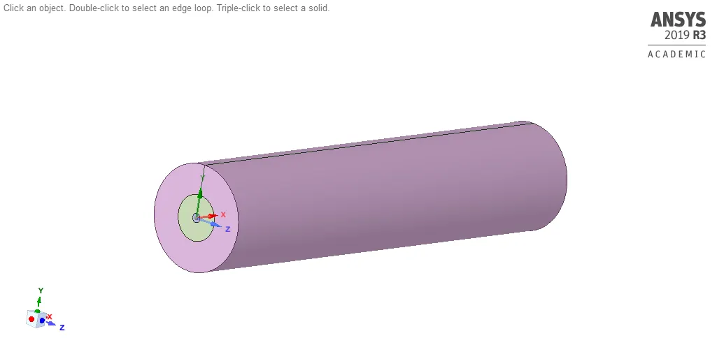
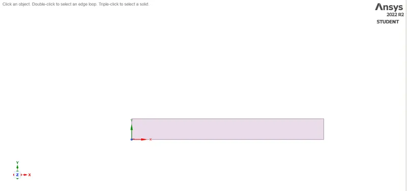
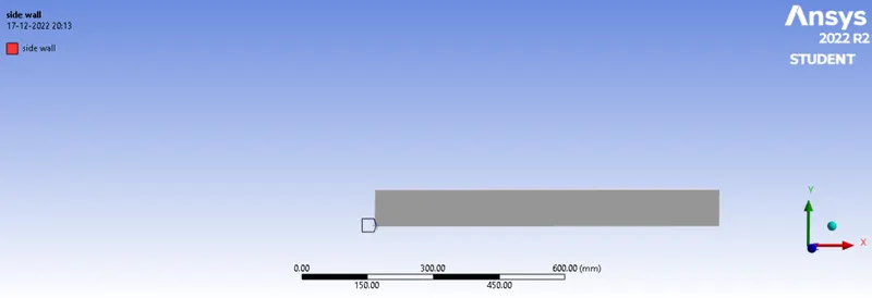
3-D geometry is converted to 2-D by using
combine bodies
inserting planes
split body
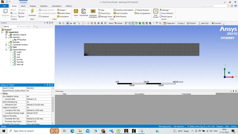
Meshing:
Element size :5mm
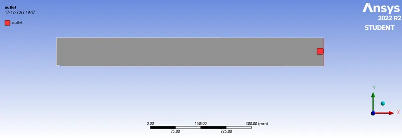
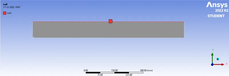
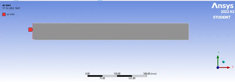
Setup:
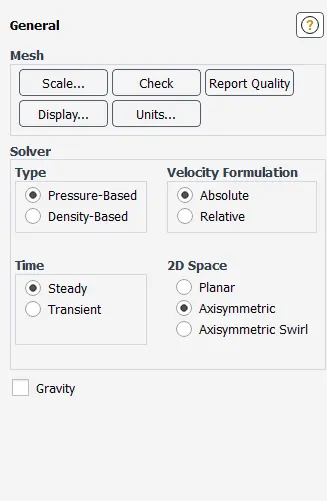
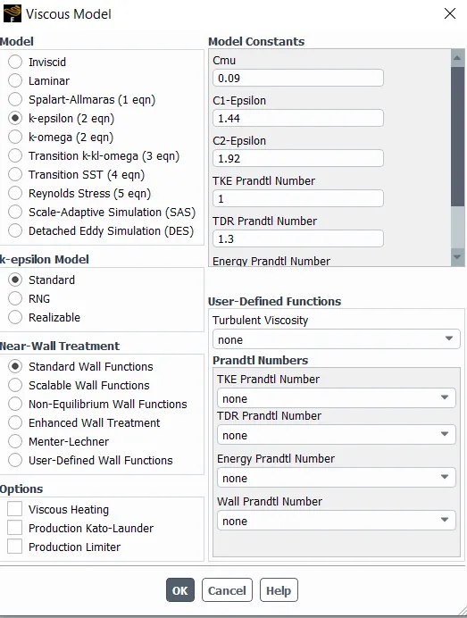
General set up and Energy is turned on.
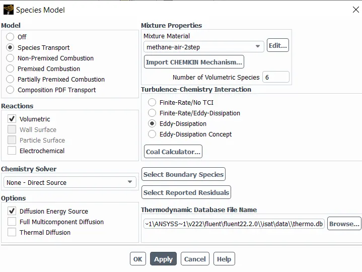
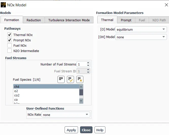
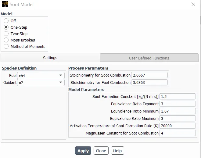
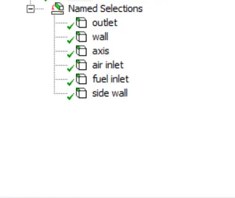
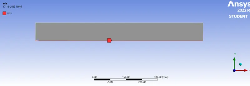
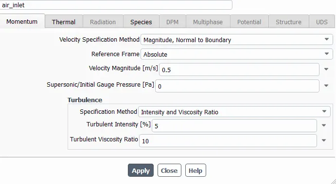
Boundary setup:
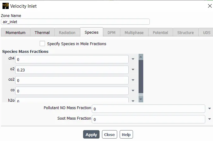
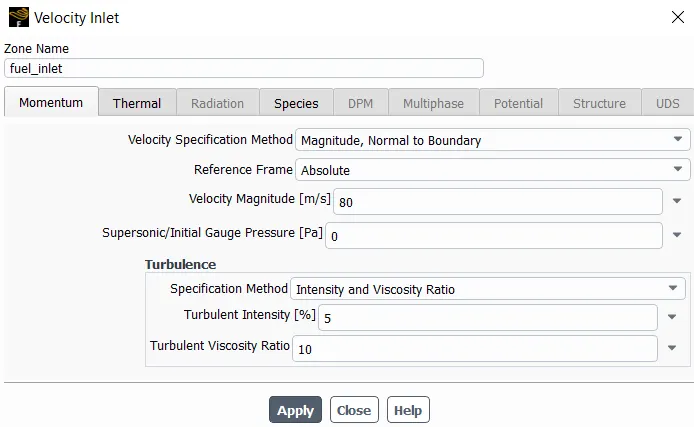
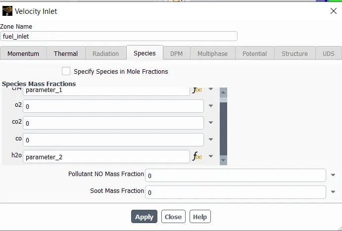
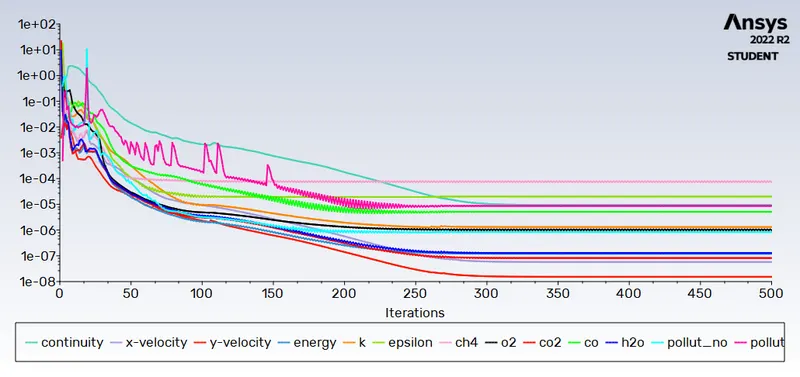
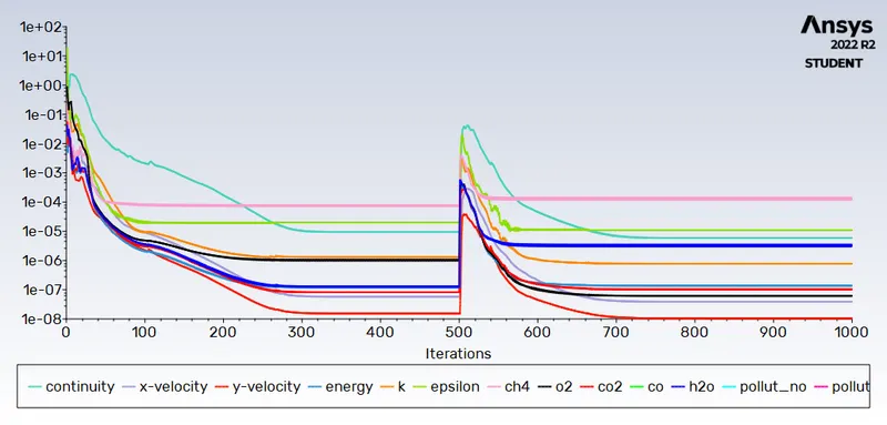
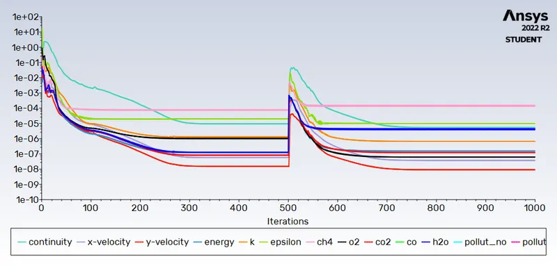
Residual:
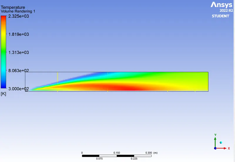
Temperature:
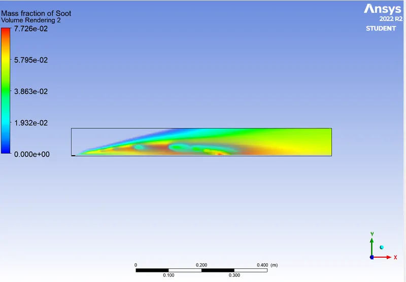
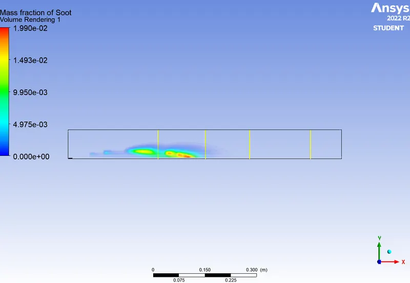
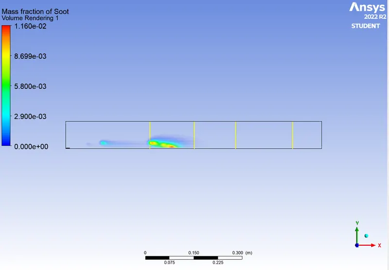
soot:
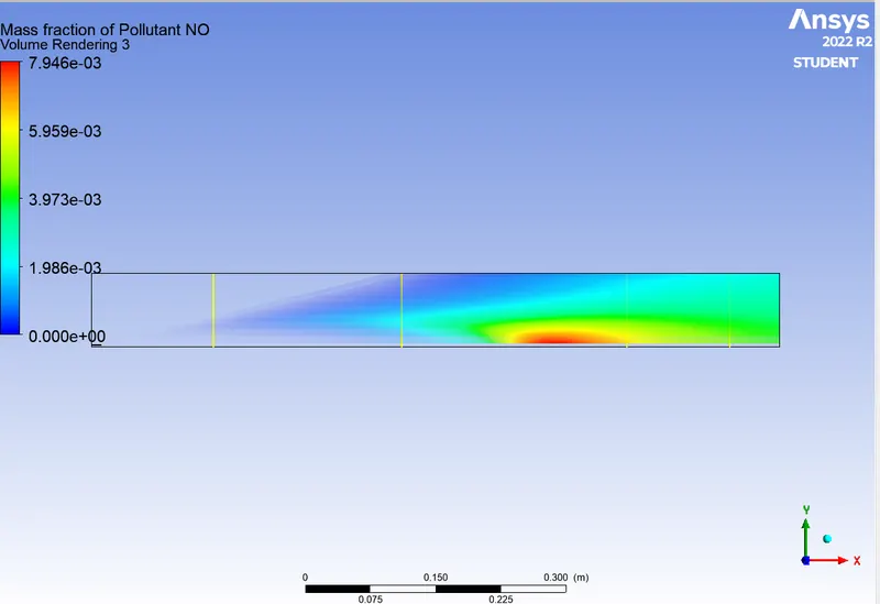
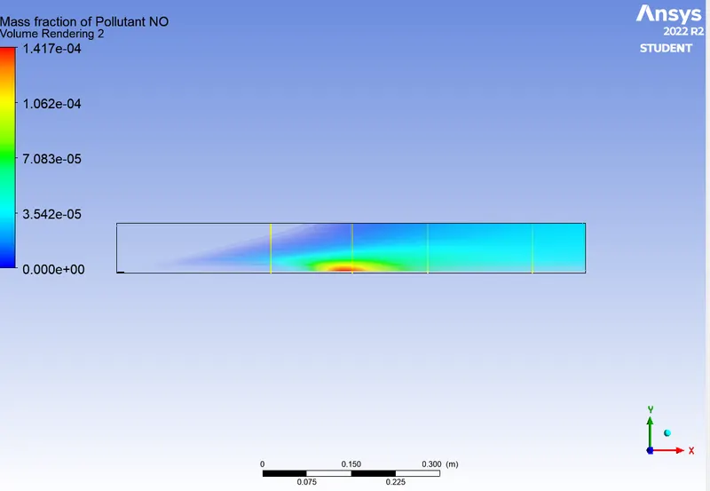
no:
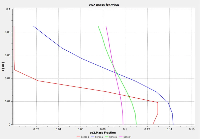
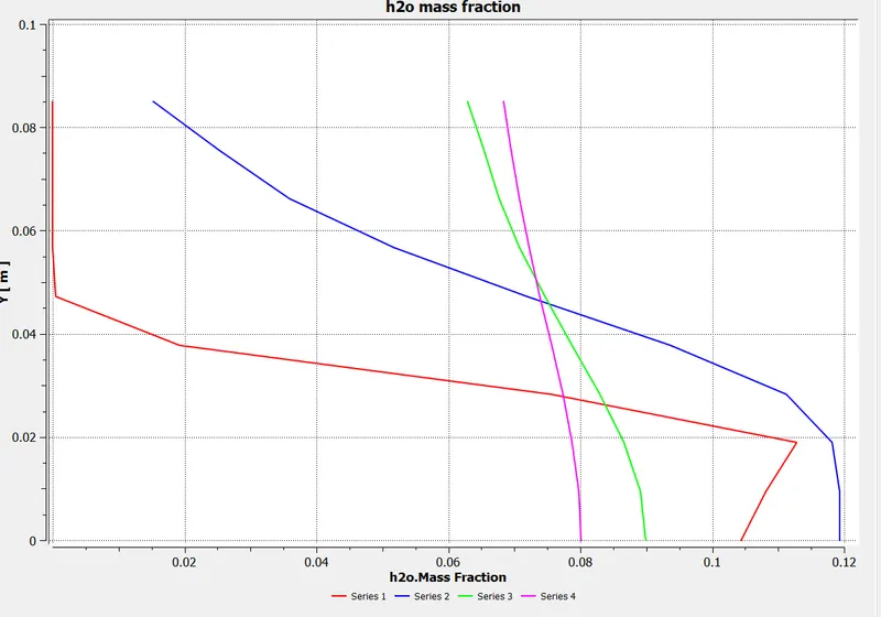
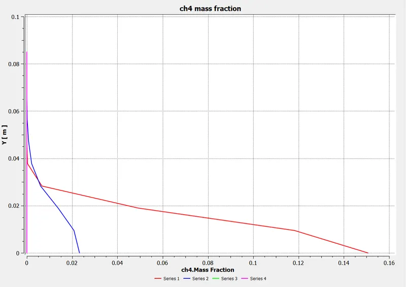
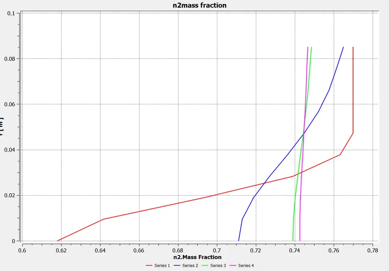
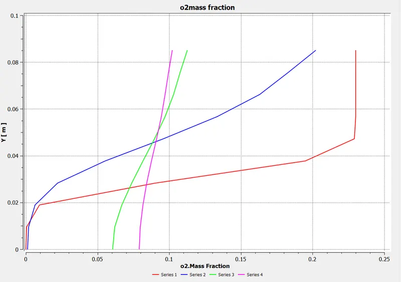

Part II
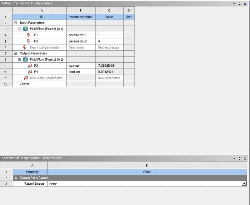
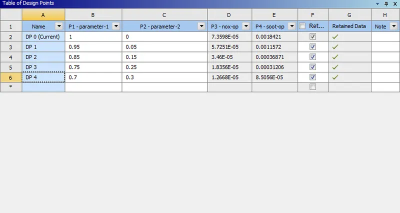
Adding the water content in the fuel from 5% to 30% by mole (Parametric study)
Results:

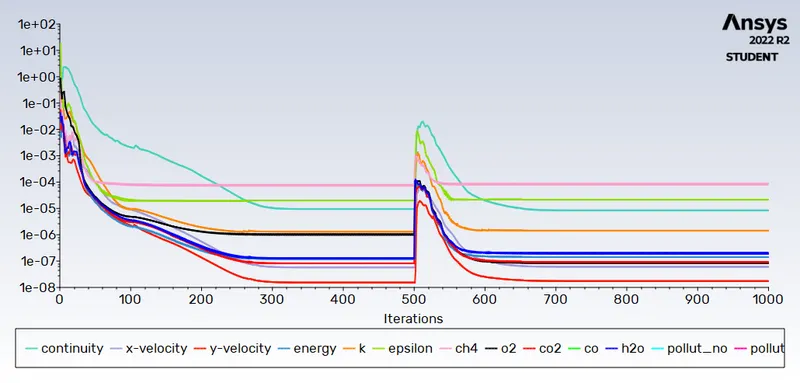
Residual:
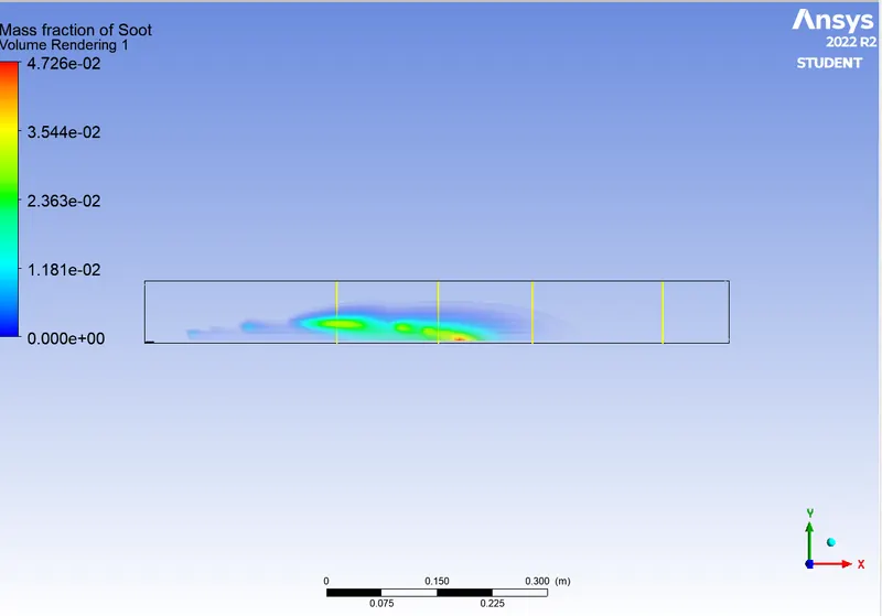
soot:
nox:

Residual:
soot:
nox:

Resisual:
soot:


Residual:
soot:
nox:
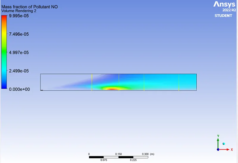
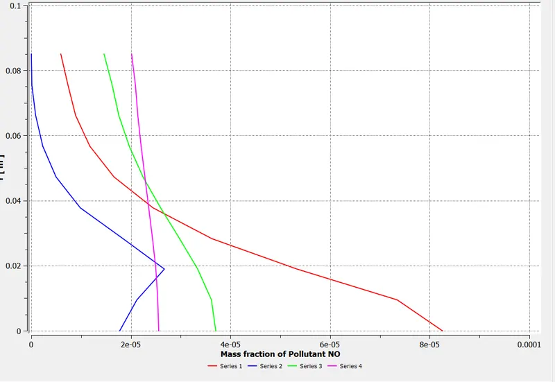
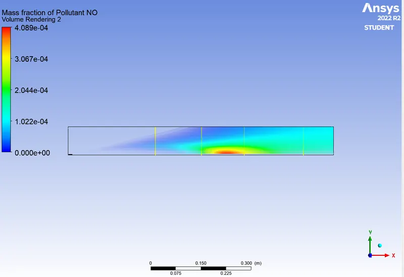
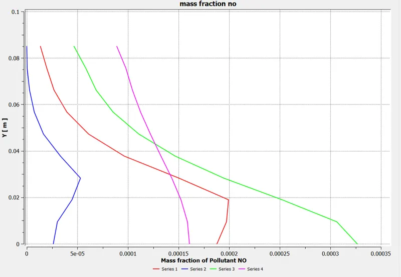
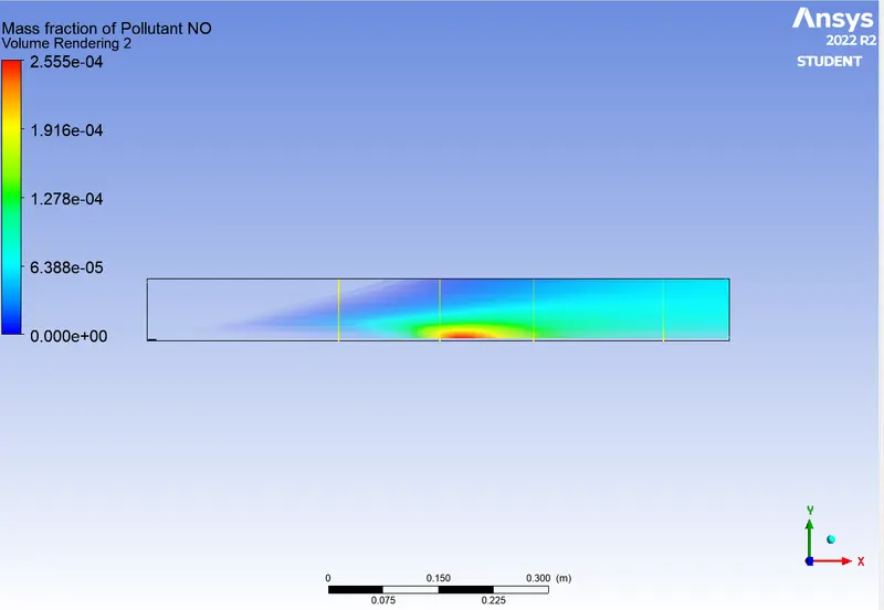
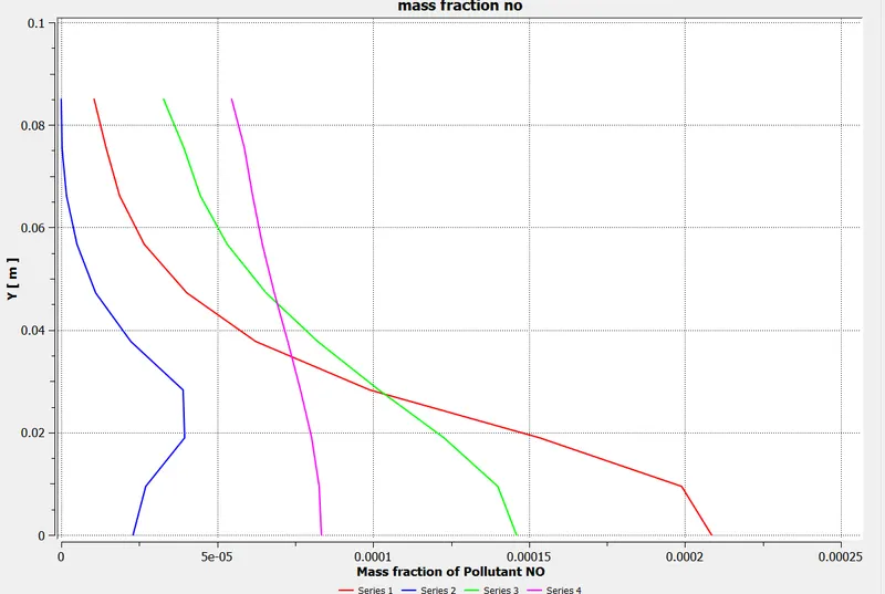
- Latent heat absorption of water particle during the combustion will lower the temperature resulting in the reduction of Pollutant NO. So Pollutant NO emissions decrease with an increase in the addition of water.
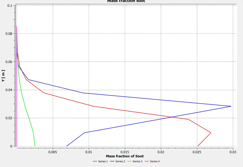
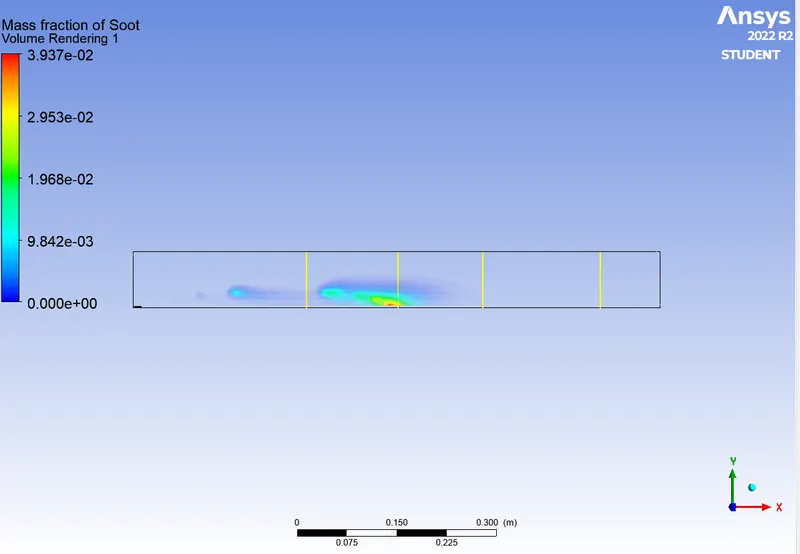
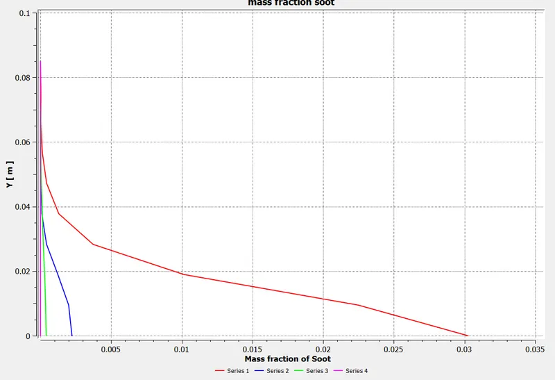
- A decrease is observed in the formation of soot particles. the lowest valve observed is in DP0 where water percentage is 0.
- Fuel dilution by H2O is a great way to reduce emissions. However, a trade-off must be made between the performance required and the dilution amount.
- Since soot value decreases with dilution we can say there is less wastage of fuel, i.e. complete combustion occurs.
- Eddy - dissipation model(Turbulence Chemistry Interaction) helps us to model combustion via turbulence mixing without the presence of an ignition source.
| DPO | SOOT
2.0743955e-05 |
NOX
0.00015445317 |
| DP1 | SOOT
3.9361225e-06 |
NOX
0.00011550263 |
| DP2 | SOOT
6.5717336e-05 |
NOX
6.5717336e-05 |
| DP3 | SOOT
6.8294595e-08 |
NOX
3.3071673e-05 |
| DP4 |
SOOT 1.3143904e-08 |
NOX
2.2244868e-05 |
Conclusion: It was realized that for a sufficient value of the large-eddy mixing time scale, kε, a combustion process could be initiated and driven by turbulence using the eddy-dissipation model, and the presence and concentration of different species, in terms of their mass fractions, involved could be visualized both along and across the combustor model. A significant decrease in the mass fraction of soot and NOx was observed due to the addition of varying water content in the fuel by mole.