Week 10 - Simulating Combustion of Natural Gas.
Aim
To perform heat transfer analysis using ansys fluent software for the cylindrical lithium-ion battery with heat generation boundary condition.
To perform mesh independent study.
Introduction
Batteries Thermal Management System
The basic types of BTMS are listed below.
1. Air cooling
2. Liquid cooling
3. Direct refrigerant cooling
4. Phase change material cooling
5. Thermoelectric cooling
6. Heat pipe cooling
Air cooling
Air systems use air as the thermal medium. The intake air could be direct either from the atmosphere or from the cabin and could also be conditioned air after a heater or evaporator of an air conditioner.
Liquid cooling
It is a cooling system in which water is used as the coolant for the purpose of cooling the battery. Liquid cooling is the most commonly used cooling system due to its convenient design and good cooling performance. Dielectric liquid cooling or direct-contact liquid which can contact the battery cells directly, such as mineral oil. The other is conducting liquid or indirect-contact liquid which can only contact the battery cells indirectly, such as a mixture of ethylene glycol and water. Depending on the different liquids, different layouts are designed.
Direct refigerant cooling
Similar to active liquid systems, a direct refrigerant system (DRS) consists of an Air Conditioning loop, but Direct Refrigerant System uses refrigerant directly as heat transfer fluid circulating throughout the battery pack.
Phase change material cooling
Phase change material absorbs heat throughout the melting process and saves it as latent heat till it reaches a maximum value. For a period, the temperature is kept at a melting point and then the temperature increase is delayed. Therefore, PCM is used as a conductor and buffer in the BTMS. Also, the PCM is always combined with another BTMS system such as liquid cooling or air cooling system to manage the battery core temperature.
Thermoelectric cooling
To improve the cooling/heating power of passive air systems, there are two possible upgrades. One is through thermo-electric modules. The thermoelectric cooling system changes the electric voltage into temperature difference and vice-versa. It removes heat through the components by exhausting electricity directly. Fans are equipped to improve heat transfer by forced convection. To blend a passive air system with the thermoelectric system and the connected system cools down the battery temperature even less than the input air temperature, and the power is limited to less than one kW. It allows with the ability to switch between cooling and heating operations and to do that only the polarity of the electrodes is needed to be reversed.
Heat pipe cooling
It’s a passive cooling system which is basically a sealed tube filled with refrigerant and it absorbs heat by vaporizing the refrigerant from the hot side and it removes heat into surrounding by condensing the refrigerant back to liquid, form on the cold side and then flows back. A partial vacuum is maintained in the casing of the heat pipe and to increase the heat transfer rate of heat pipes a capillary structure is used within the heat pipes which increases the surface temperature. The heat pipe may use water or any refrigerant as the coolant and this cycle repeats again and again. The battery acts as a heat source and sits below the heat pipe (on the evaporating side) and the cooling fins acts as the heat sinks on the heat pipe (on the condensing side). According to experiments, a reduction of 30% in the thermal resistance is found for heat pipe cooling system under natural convection as compared to without heat pipe. A thermal resistance reduction of 20% under low air velocity convection is possible. The main problem with this cooling is the safety of the system which can be a concern in the case of an emergency; a short circuit can happen due to the coolant leakage on the battery cells which can cause a failure of the vehicle and can be fatal. Also, the capillary tubes require a minimum diameter to maintain an adequate pressure drop and avoid blockage.
Geometry
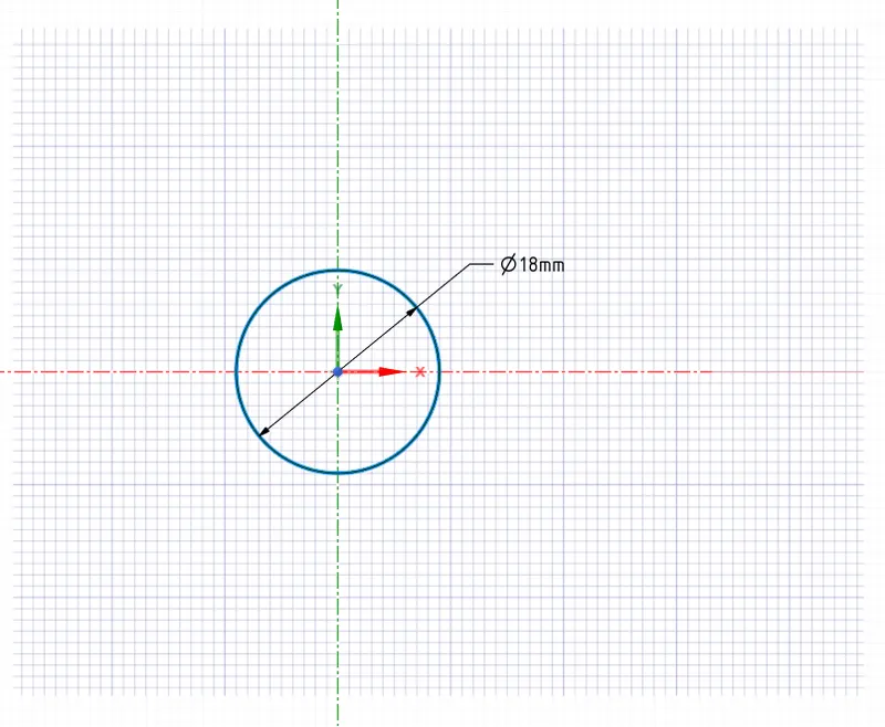
Geometry starts with the simple sketch of circle 18 mm diameter which is the diameter of a cylindrical battery.
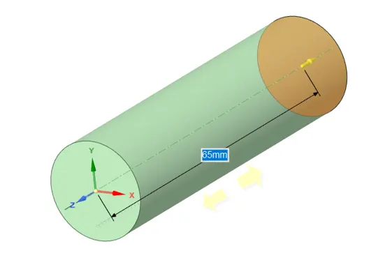
Using pull tool its surface is extended upto 65 mm which is the height of a battery.
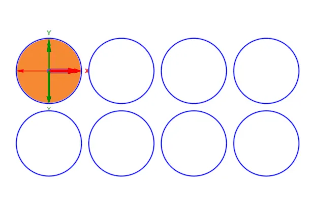
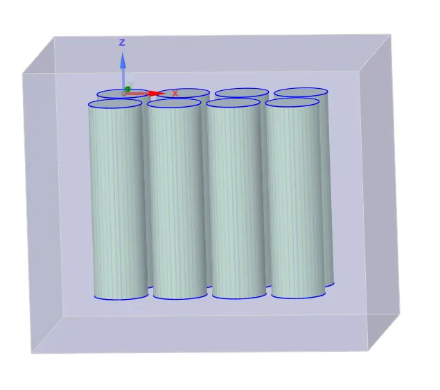
After which a linear pattern is made with 4 x 2 battery pack system along x and y direction.
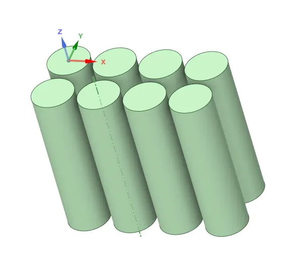
An enclosure is created for its fluid domain.
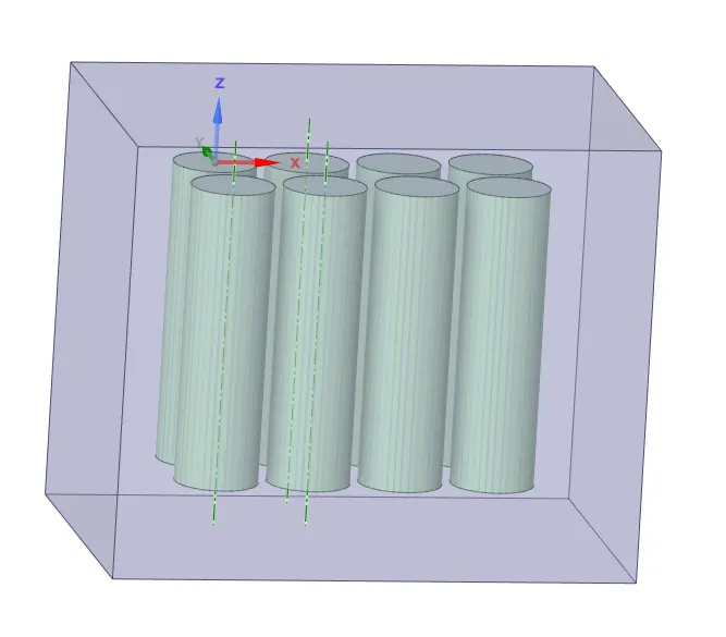
A share topology is enabled in order to get conformal mesh.
Mesh
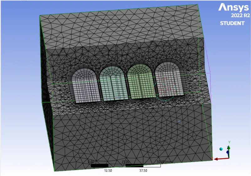
Mesh is generated with the element size of 8 mm.
Total mesh elements is 157298 for first three cases with the space between batteries as 2 mm and varrying velocity of air as 3, 5 and 10 m/s.
Total mesh elements for case four and five are 159674 and 169293. Case four and five have space between batteries as 4mm and 6mm respectively.
For mesh independent study total mesh elements used are 361347 and 483090.
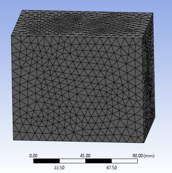
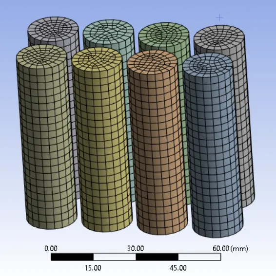
A program controlled inflation layer is opted with maximum layers of 5 and growth rate of 1.2 .
Solver settings
A steady state pressure based solver is opted.
Energy is turned on as temperature is involved.
Viscous model : k - omega - SST
Material properties :

Material for the batteries is Lithium-ion.
Material for fluid domain is polystyrene.
It is assumed that battery pack system (4x2) generates heat in the amount of 48750 W/m3.
For this under cell zone conditions of battery source term is enabled with the energy source value of 48750 W/m3.
Boundary conditions :
Inlet = Velocity inlet (air)
Convection wall which is fluid domain having the thermal conditions of convection with heat transfer coefficient of 5 W/m2K.
Free stream temperature is set as 26 degree celcius.
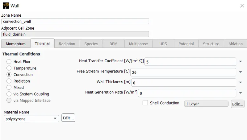
Initialization is done using Hybrid method and the solution method opted is coupled scheme.
Results
Case : 1
Space between the batteries 2 mm and inlet velocity of air 3 m/s
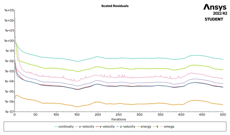
Residuals
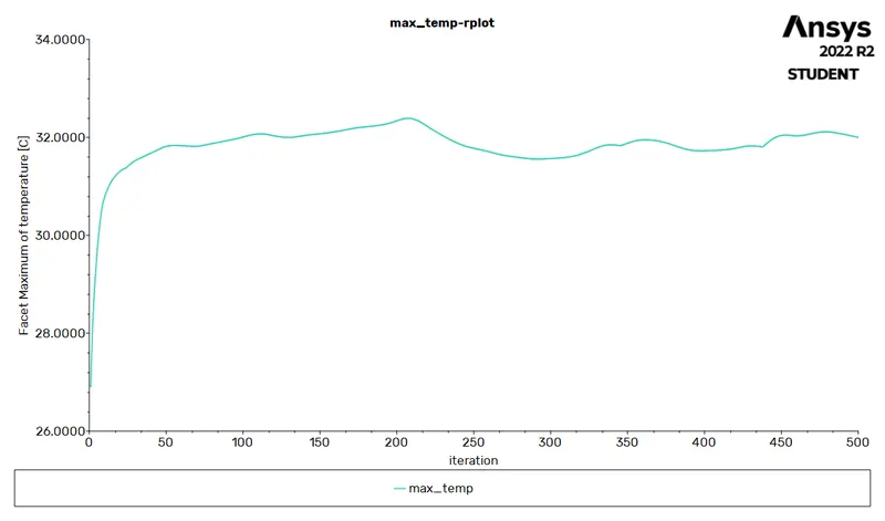
Maximum temperature
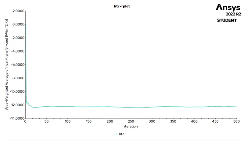
Heat transfer coefficient
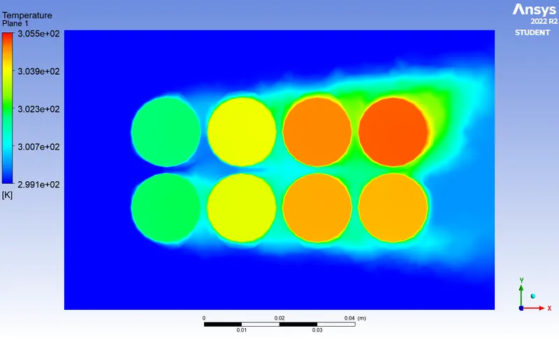
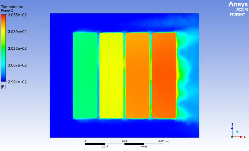
Temperature contour
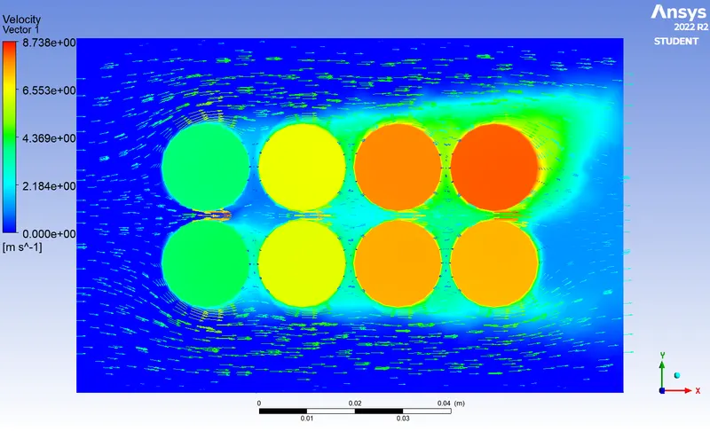
Velocity vector
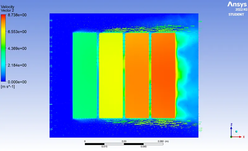
Animation
https://drive.google.com/file/d/1JrjCxrk7pJDDCRwzAk_BZEsg15L4q4oa/view?usp=share_link
Case : 2
Space between the batteries 2 mm and inlet velocity of air 5 m/s
Residuals
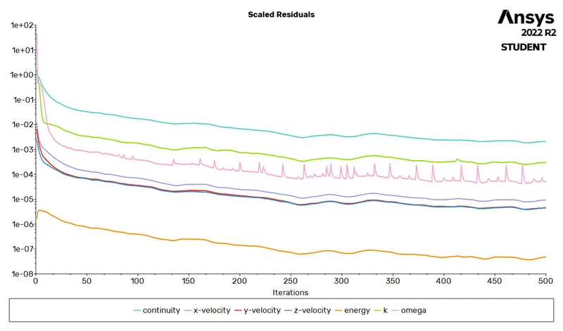
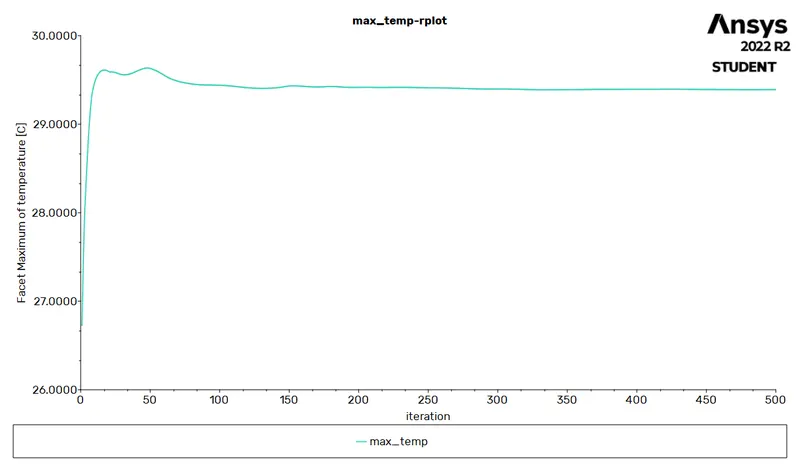
Maximum temperature
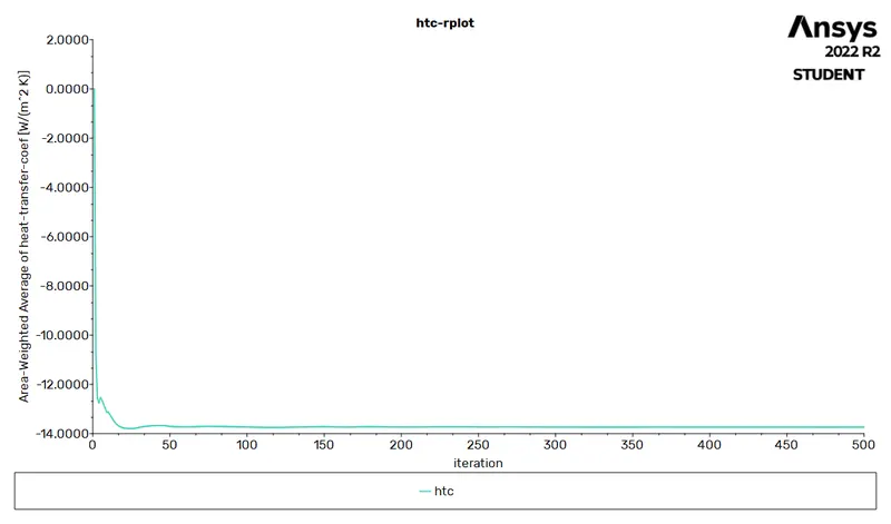
Heat transfer coefficient
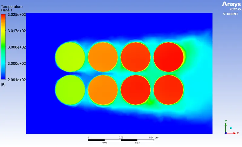
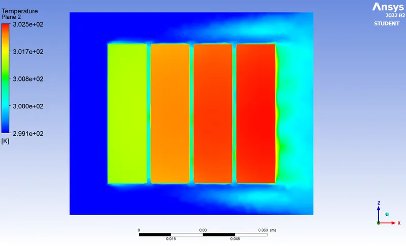
Temperature contour
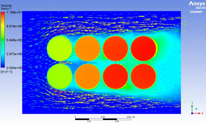
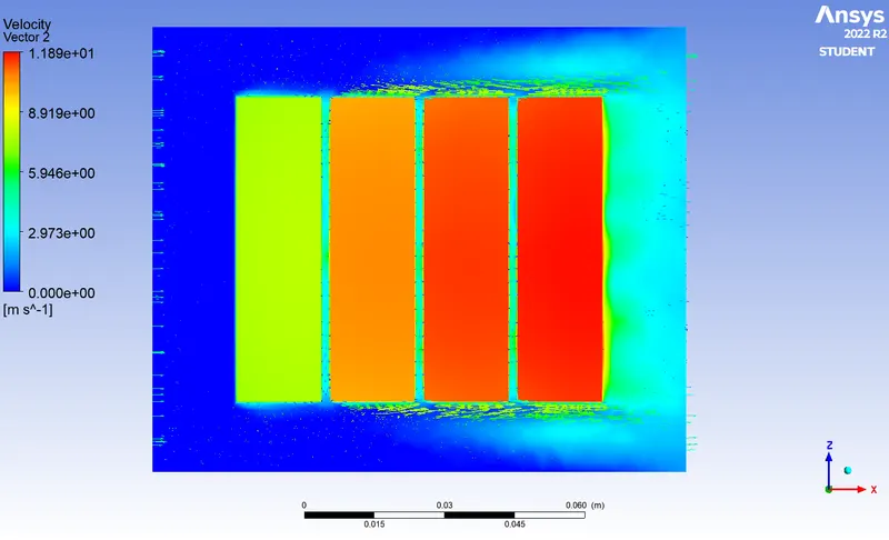
Velocity vector
Case : 3
Space between the batteries 2 mm and inlet velocity of air 10 m/s
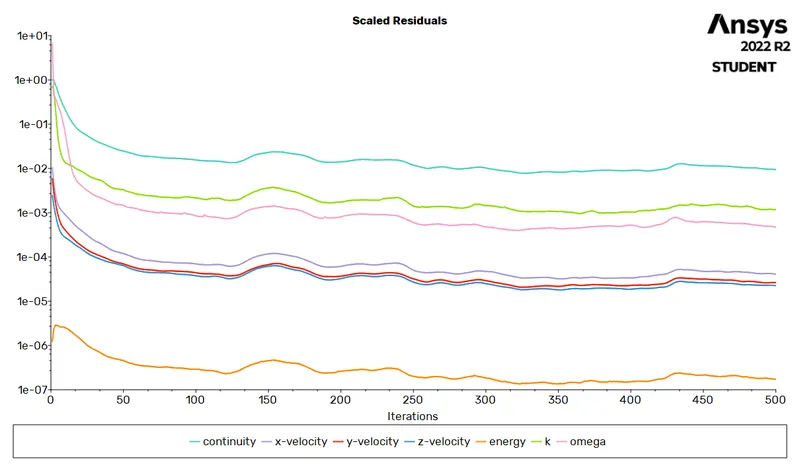
Residuals
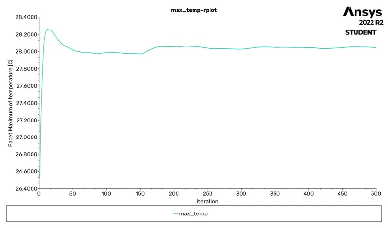
Maximum temperature
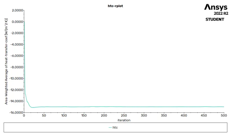
Heat transfer coefficient
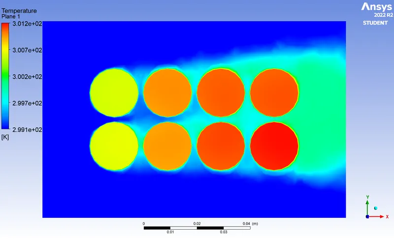
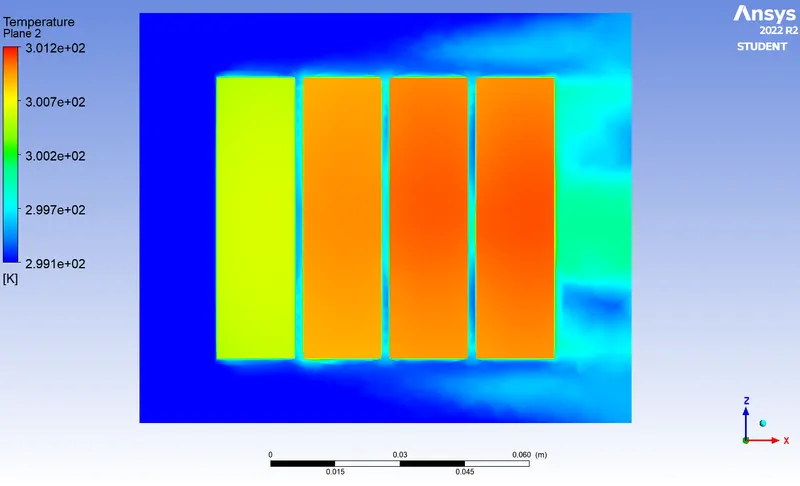
Temperature contour
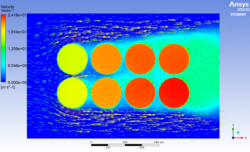
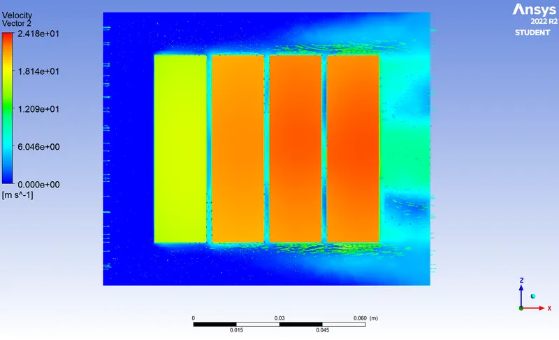
Velocity vector
Case : 4
Space between the batteries 4 mm and inlet velocity of air 3 m/s
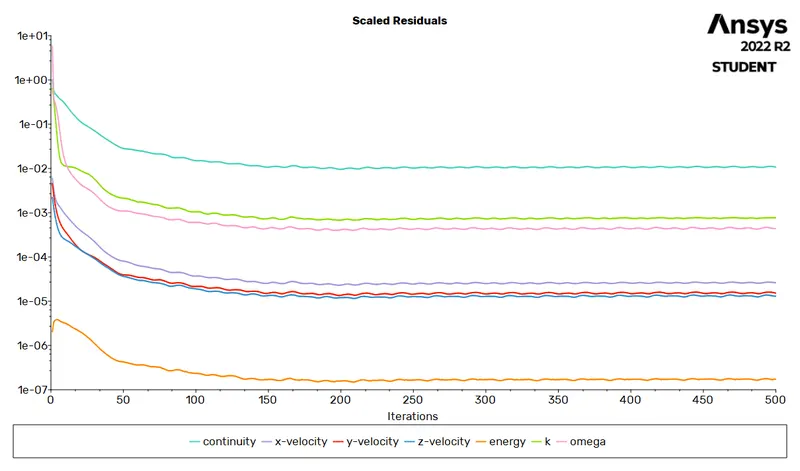
Residuals
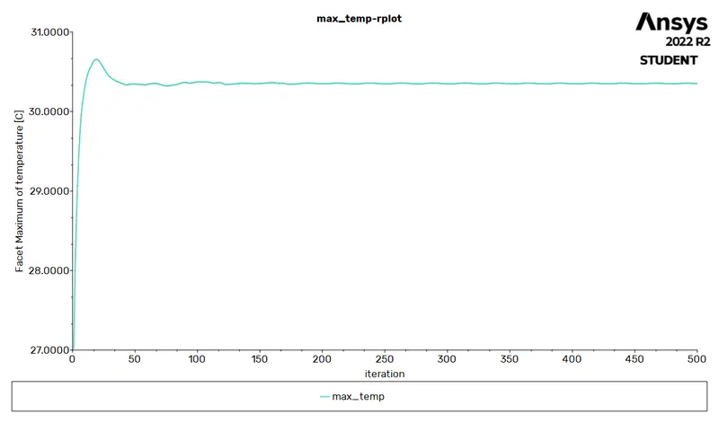
Maximum temperature
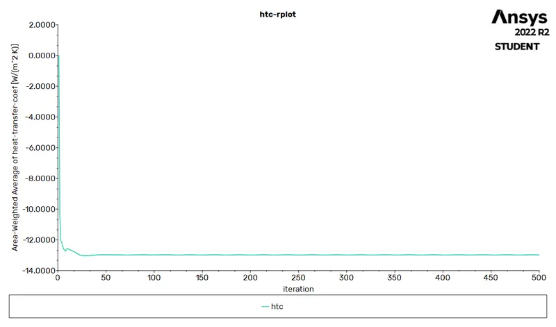
Heat transfer coefficient
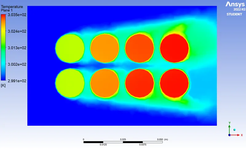
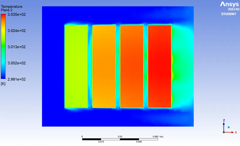
Temperature contour
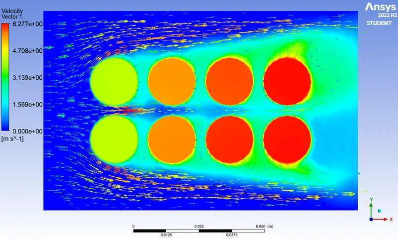
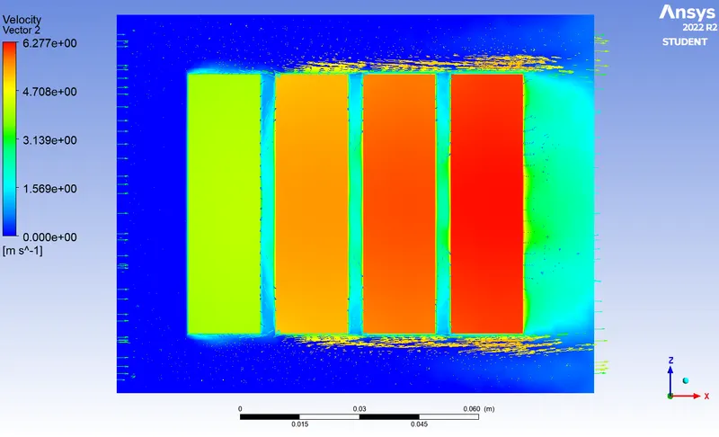
Velocity vector
Case : 5
Space between the batteries 6 mm and inlet velocity of air 3 m/s
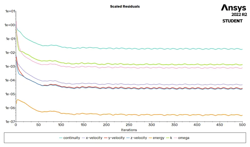
Residuals
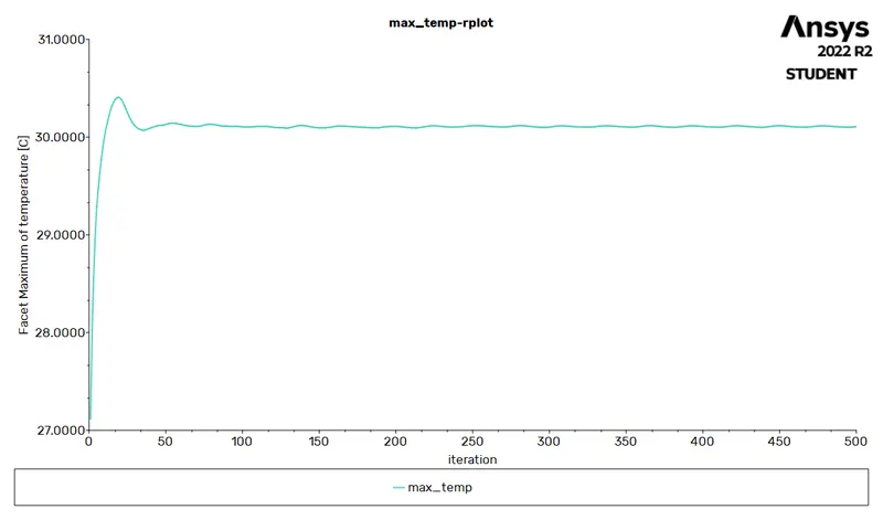
Maximum temperature
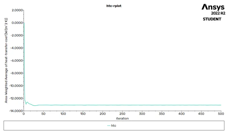
Heat transfer coefficient
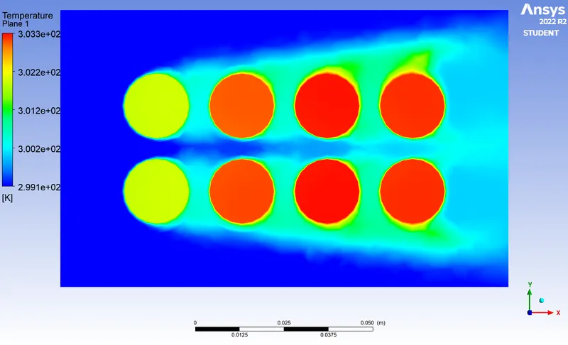
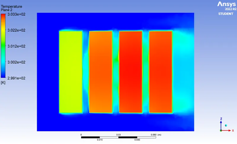
Temperature contour
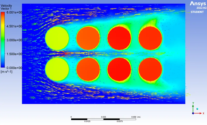
Velocity vector
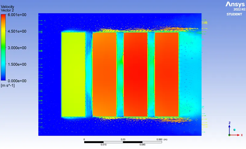
Mesh Independent Study :
Case : 6 (Total mesh elements = 361347)
Space between the batteries 2 mm and inlet velocity of air 3 m/s
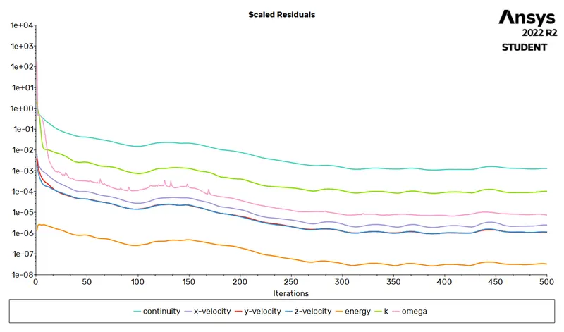
Residuals
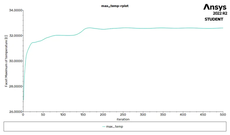
Maximum temperature
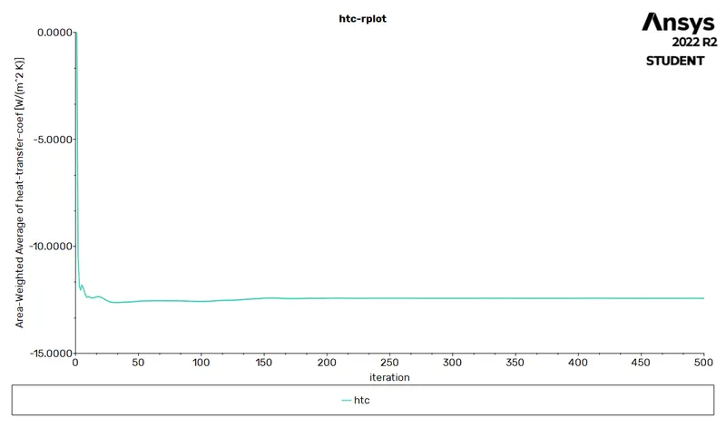
Heat transfer coefficient
Temperature contour
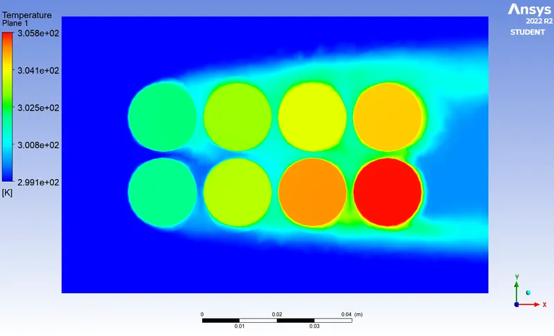
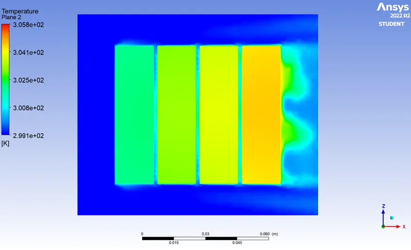
Velocity vector
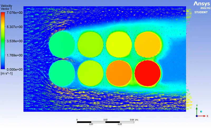
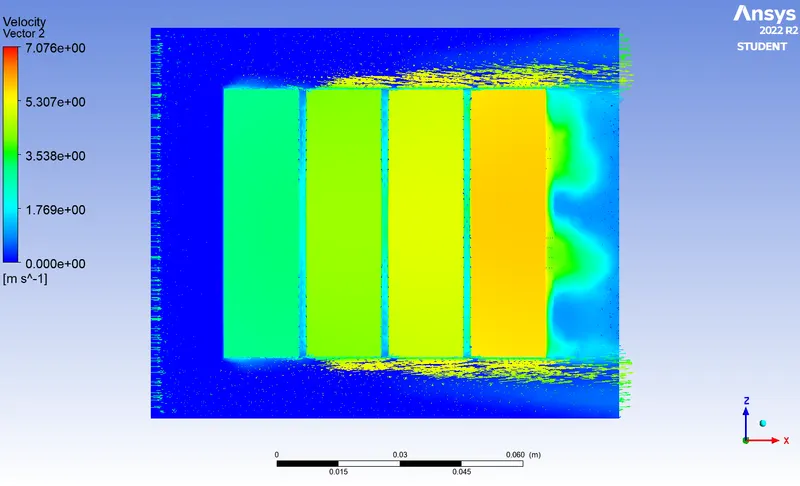
Case : 7 (Total mesh elements = 483090)
Space between the batteries 2 mm and inlet velocity of air 3 m/s
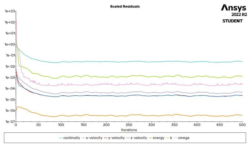
Residuals
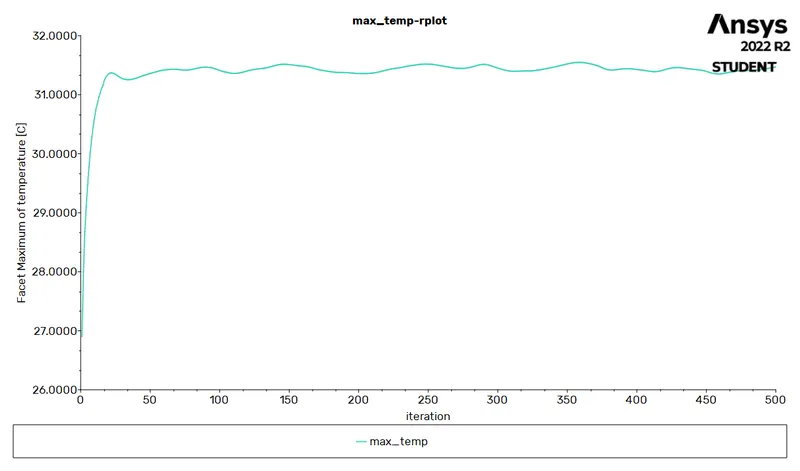
Maximum temperature
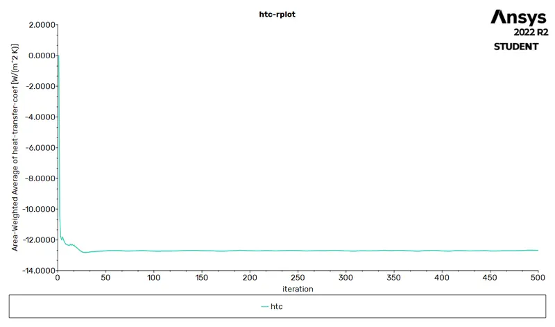
Heat transfer coefficient
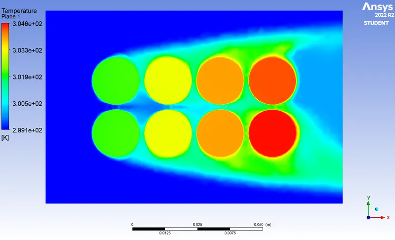
Temperature contour
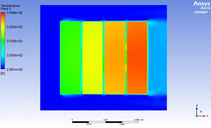
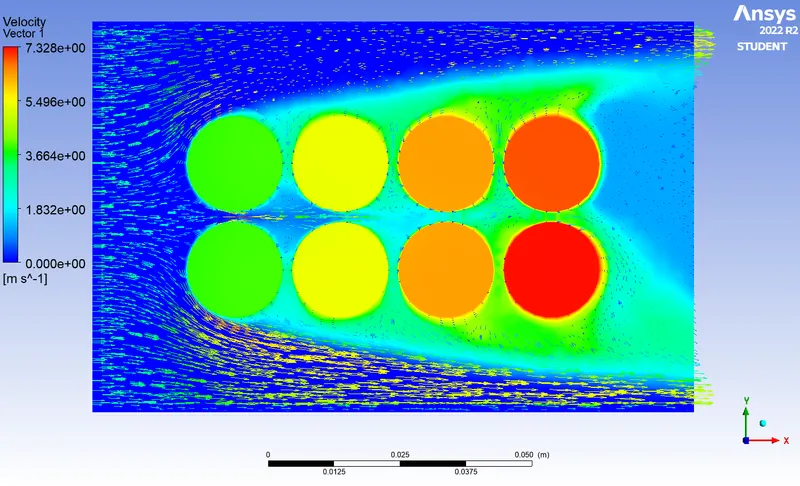
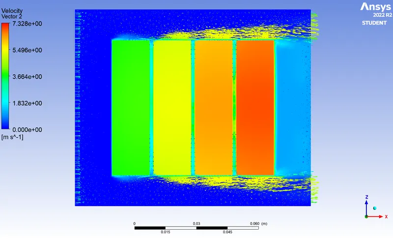
Velocity vector
Conclusion



Heat transfer coefficient increases with increase in inlet velocity of air. The maximum temperature obtained by the batteries is reduced as the inlet velocity of air increases.
By increasing the space between the batteries the maximum temperature of the battries are reduced at the same time heat transfer coefficient increases slightly. Negative sign indicates that heat is rejected by the system.
From mesh independent study able to see the variation in results with respect to mesh. For refined mesh the results accuracy could be obtained. Disadvantage is that computational time is high.