Week 10 - Simulating Combustion of Natural Gas.
Aim:
- To perform the combustion simulation on the combustor model and plot the variation of the mass fraction of the different species in the simulation using line probes at different locations of the combustor and also plot CO2, H2O, CH4, N2, O2, NOx emissions & soot formation.
- Addition of water from 5% to 30% by mole in the fuel and its effect in the formation of NOx and Soot.
Theory:
- A combustor is a component or area of a gas turbine, ramjet or Scramjet engine where combustion takes place. It is also known as the burner, combustion chamber or flame holder.
- In gas turbine Engine the combustor or combustion chamber is fed high pressure air by the compression system. The combustor then heats this air at the constant pressure as the fuel/air mix burns.
- The fuel/air mix burns and producing heat and expands rapidly, burned mis is exhausted from the combustor through the nozzle guide vanes of the turbine.
- Combustor must contain and maintain stable combustion despite very high air flow rates. Hence combustors are designed to first mix and ignite air & fuel, then mix in more air to complete the combustion process.
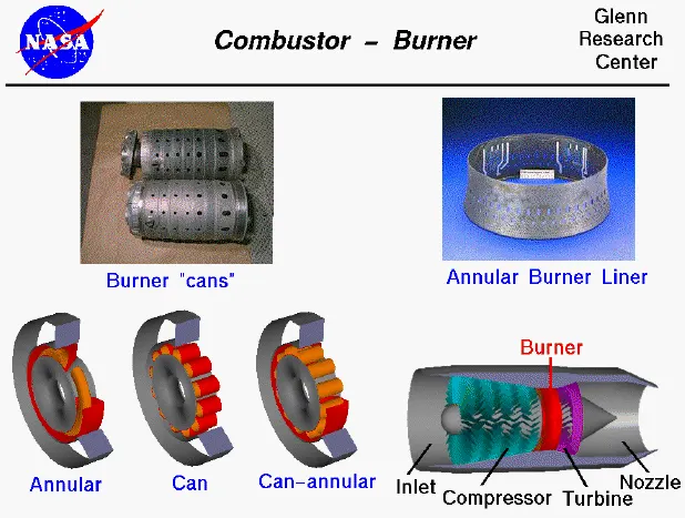
- There are three main types of combustors used now a days Can, Annular & Cannular. We are using Can type combustor for the current simulation.
NOx:
- In atmospheric chemistry the term NOx denotes the total concentration of NO & NO2, Since the conversion between these two species is rapid in the stratosphere & troposphere.
- At high temperature Oxygen & Nitrogen undergo Endothermic Reaction producing various oxides of Nitrogen.
- Such high temperature can be found in IC engine, Combustor etc.
Soot:
- Soot particle is usually formed due to incomplete combustion of fuel or pyrolysis in a rich mixture of hydrocarbon fuel with strong temperature gradient in the combustion chamber.
- Instead of complete combustion of fossil fuel most burn at lower temperature with slightly reduced supply of oxygen.
- When fossil fuel burns, it breaks into small particles that includ e soot, which settles out as a dark powdery deposit.
Simulation setup:
- Import the combustor model in the Ansys Fluent Geometry.
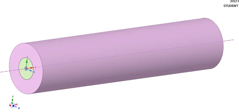
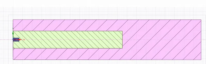
- Since the simulating on the whole model will increase the resources, as the whole model is axis symmetry hence considering 2D model for the simulation.
- Using the split body option Cut the model in 270 degree and remove the part, then select the 2D model and save the mode.


- Import the 2D geometry and Choose 0.002m mesh element size with proximity kept ON.
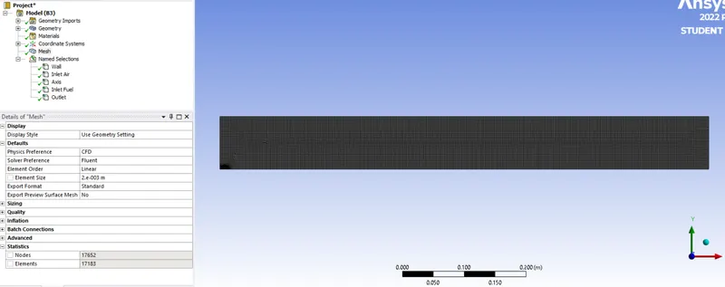
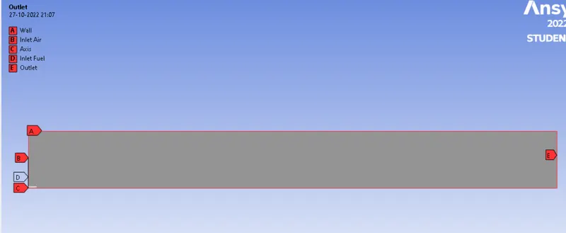
- Choose steady state simulation with axis symmetry, Energy enabled.
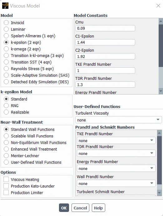
- Choose K-epsilon turbulence model, Standard, Standard Wall Function
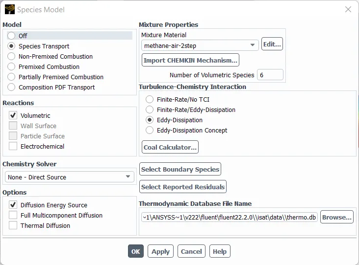
- Species Model
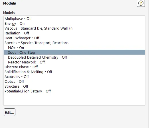
- NOx Model

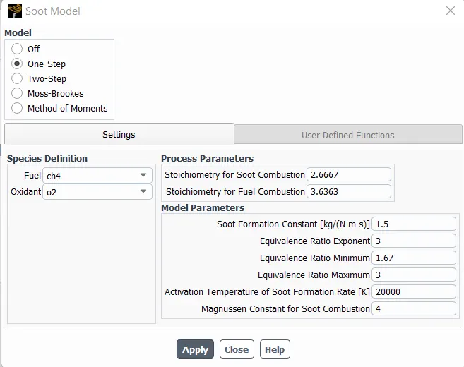
- Soot Model
- Boundaries:
Inlet Air: Velocity: 0.5m/s
Temperature: 300K
Species: Mass Fraction of O2 = 0.21
Inlet Fuel: Velocity: 80m/s
Temperature: 300K
Species: Mass Fraction of CH4 & H2O (as per case)
- Create the Input parameter for the Input fuel by, Boundaries >> Input Fuel >> Species >> CH4 & H2O >> Set as Input parameter.
- Within the CFD Post create Output parameter for Outlet Temperature, Mass Fraction of NO & Soot. Ansys Result >> Expression >> right click New >> Within Window Right click Function >> CFD post >> Area Average >> Right Click Variable >> Temperature >> Right Click Location >> Outlet >> Apply >> Right click on the Created Expression And set as Output parameter.
Part 1 : Mass fraction of CH4 is 1
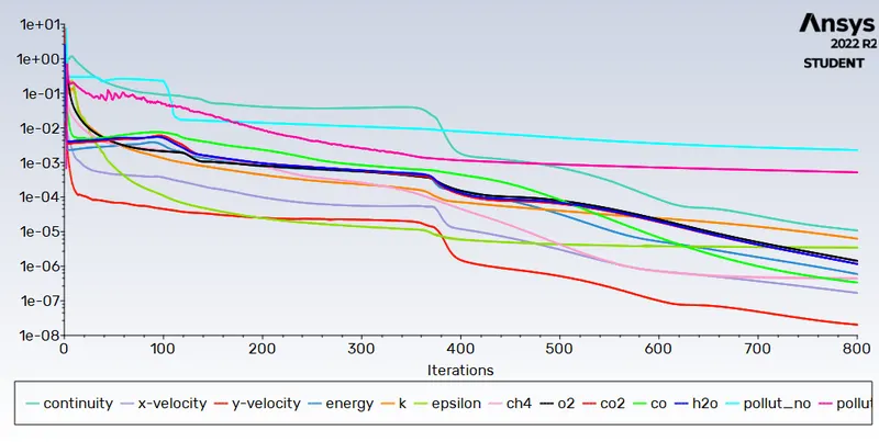
- Residual:
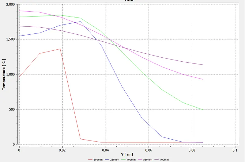
- Outlet Temperature Plot:
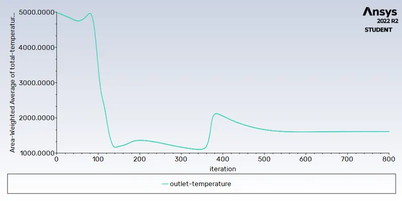
- Outlet Temperature Contour:
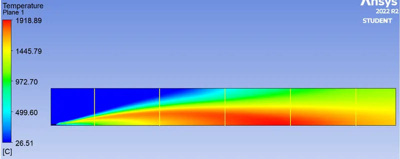
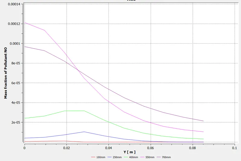
- Mass Fraction of NO Contour:

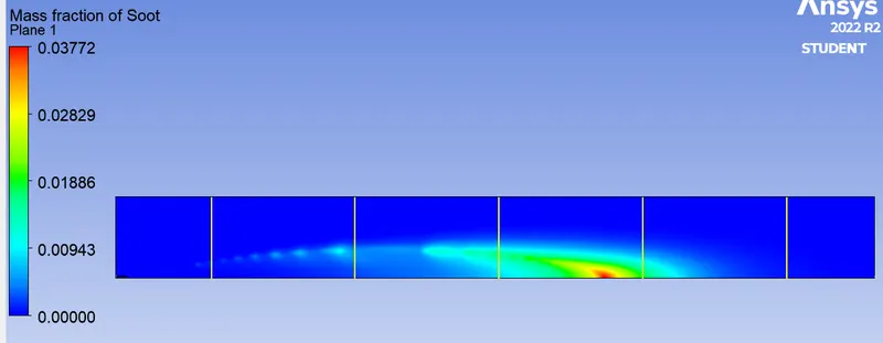
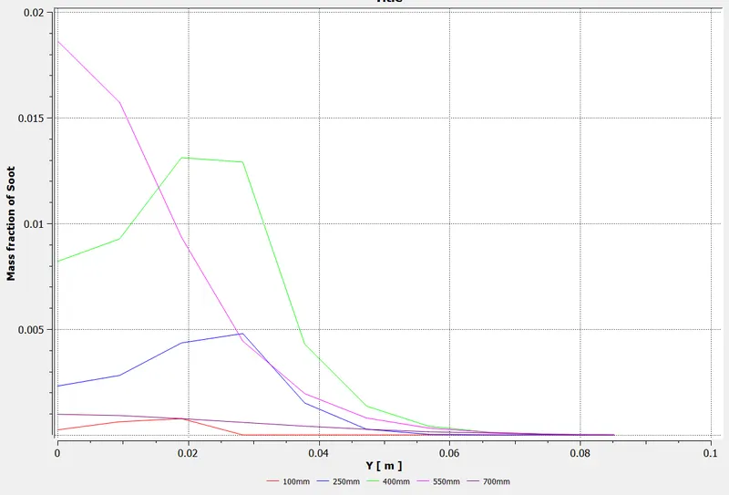
- Mass Fraction of Soot Contour:
- Mass Fraction of CH4 Contour:
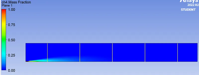
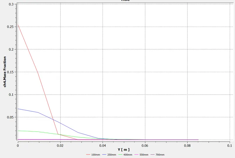
- Mass Fraction of H20 Contour:
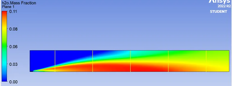
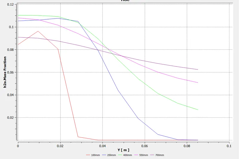
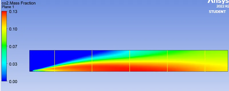
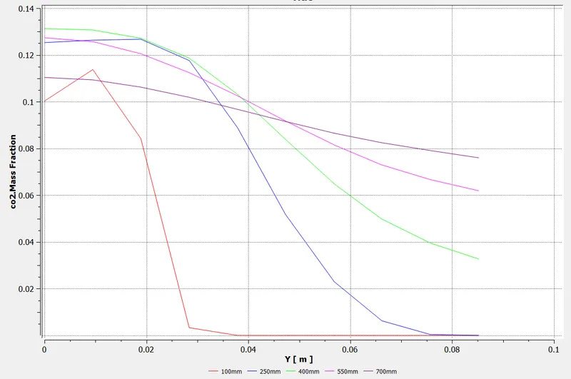
- Mass Fraction of C02 Contour:
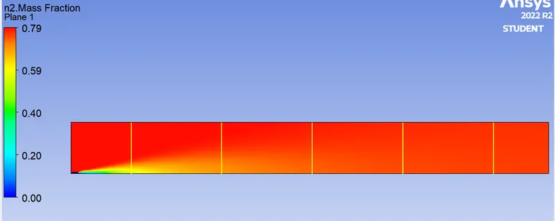
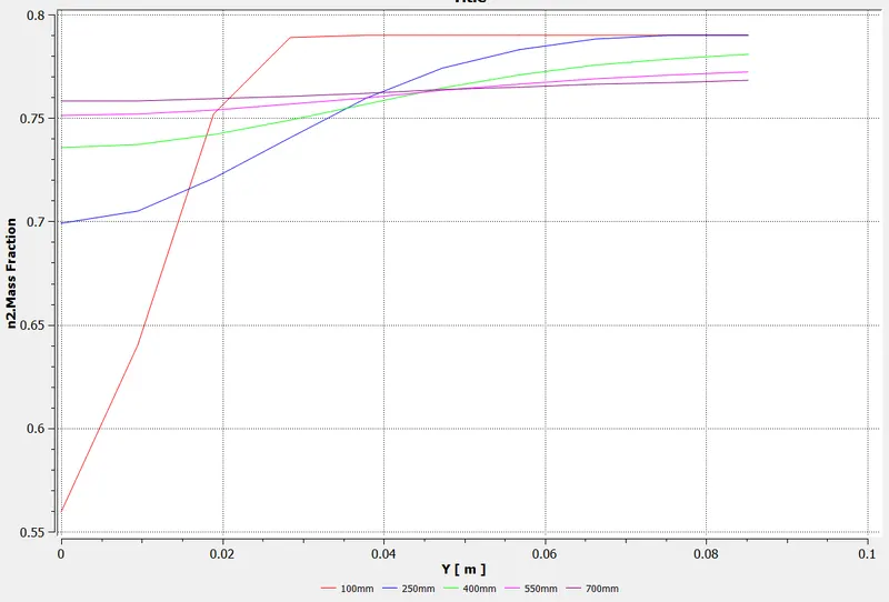
- Mass Fraction of N2 Contour:
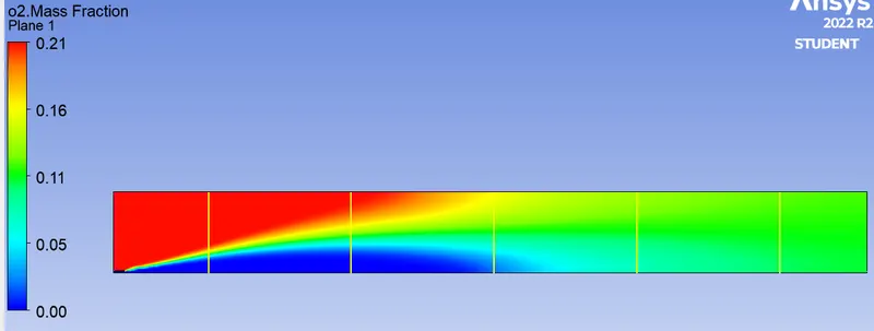
- Mass Fraction of O2 Contour:
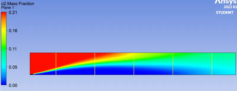
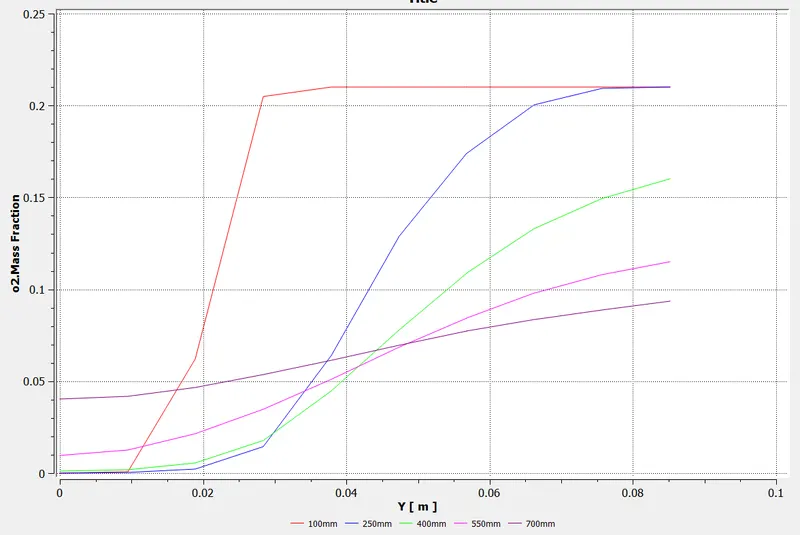
Part 2: Inclusion of water content in fuel
Case-a: Mass fraction of CH4 is 0.95 & H2O is 0.05
- Residual:
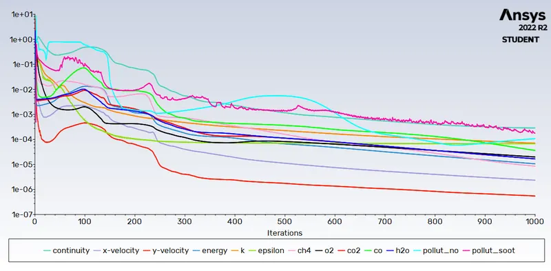
- Outlet Temperature Plot:
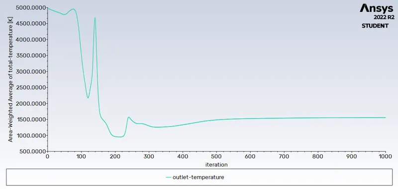
- Outlet Temperature Contour:
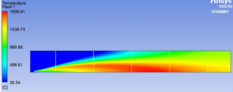
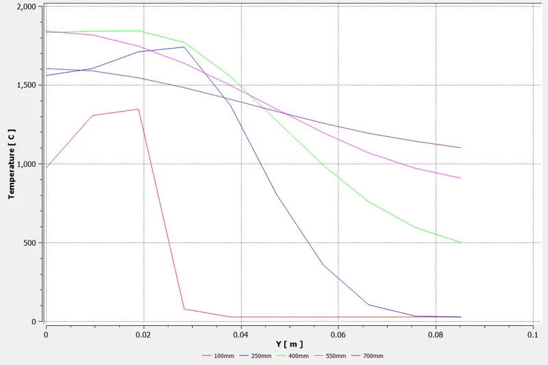
- Mass Fraction of NO Contour:
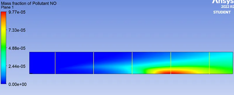
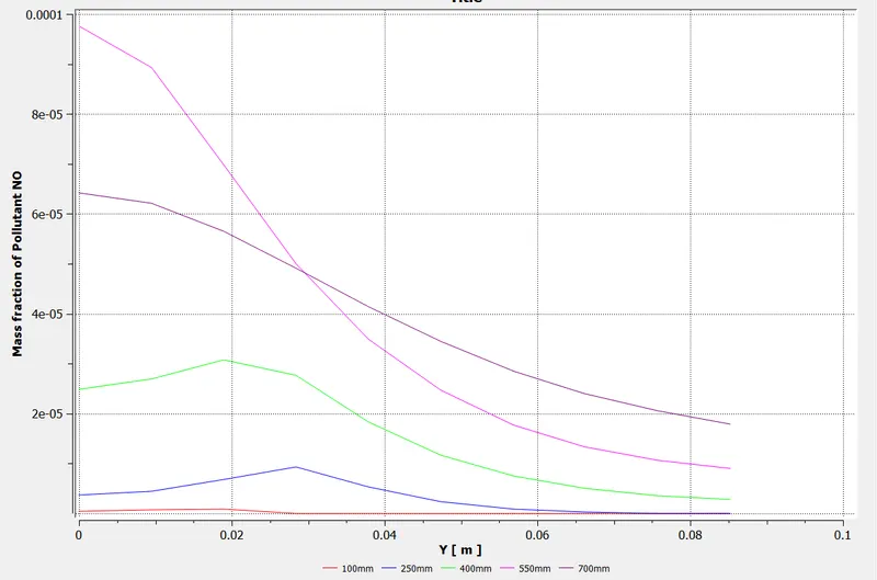
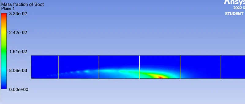
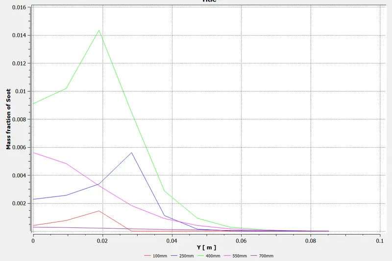
- Mass Fraction of Soot Contour:
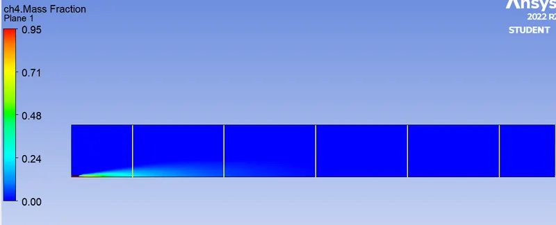
- Mass Fraction of CH4 Contour:
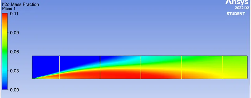
- Mass Fraction of H20 Contour:
- Mass Fraction of C02 Contour:

- Mass Fraction of N2 Contour:
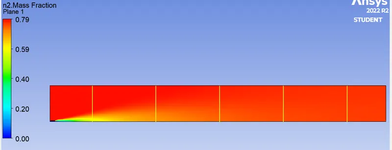
- Mass Fraction of O2 Contour:
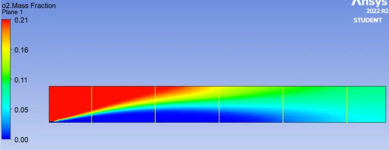
Case-b: Mass fraction of CH4 is 0.9 & H2O is 0.1
- Residual:
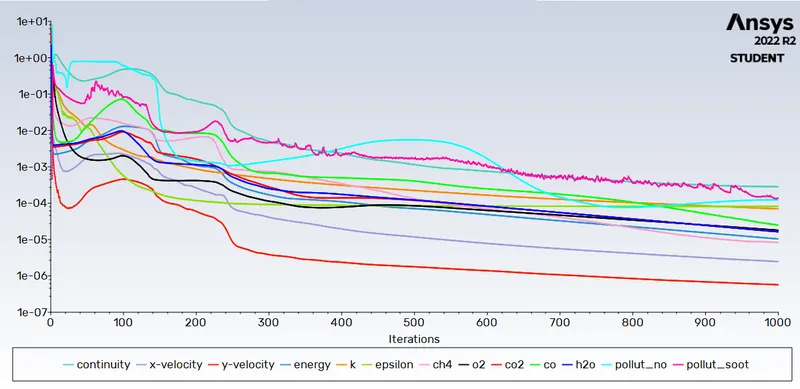
- Outlet Temperature Plot:
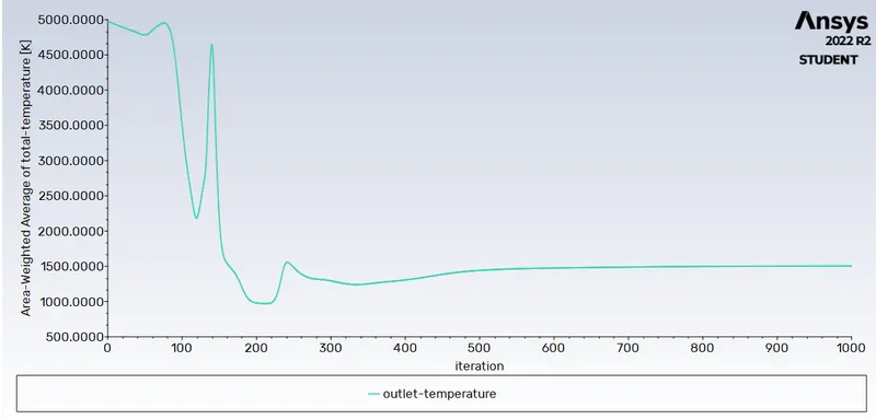
- Outlet Temperature Contour:
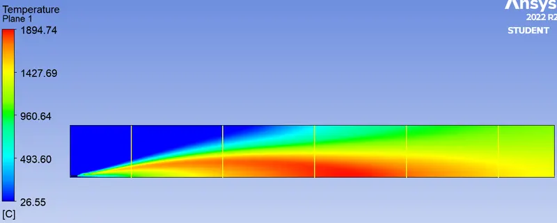
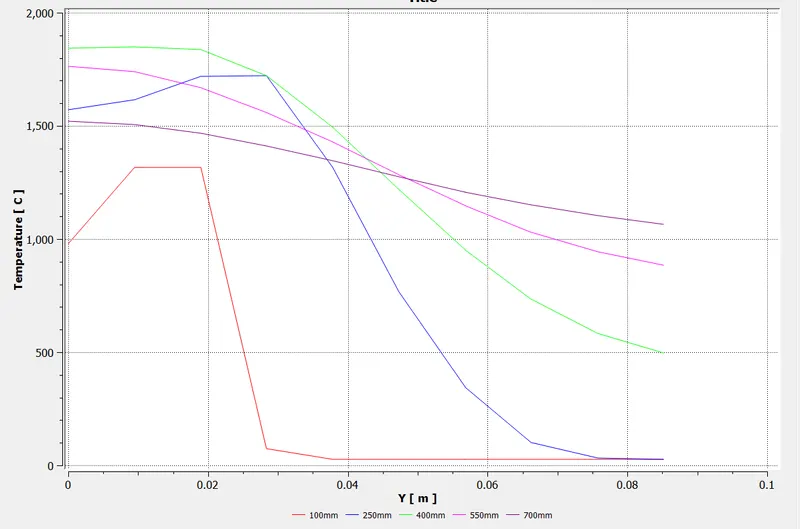
- Mass Fraction of NO Contour:
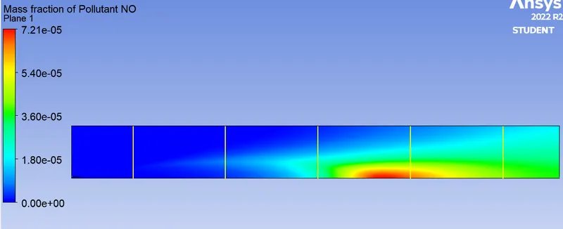
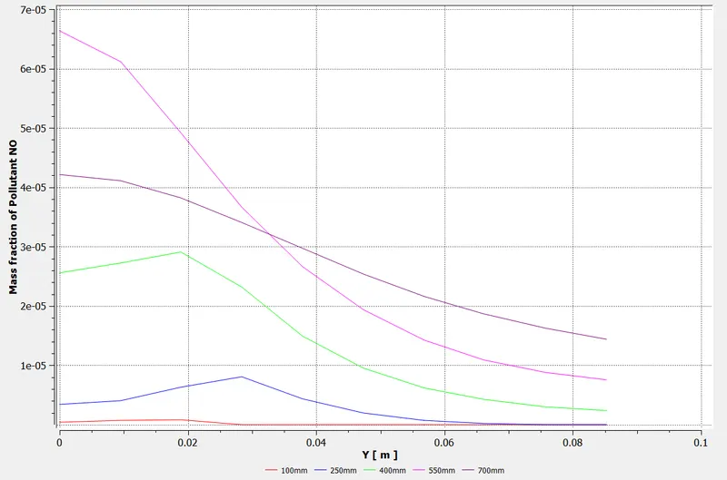
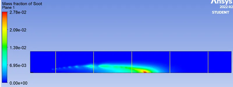
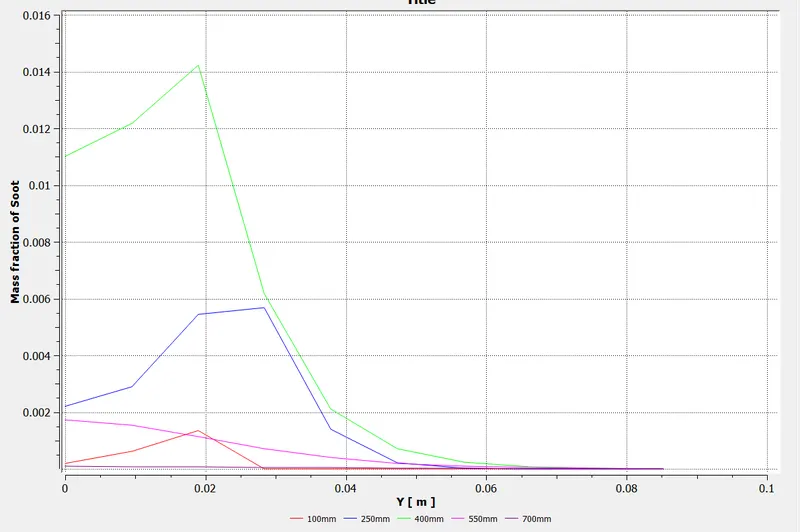
- Mass Fraction of Soot Contour:
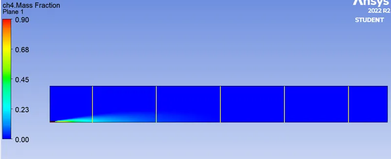
- Mass Fraction of CH4 Contour:
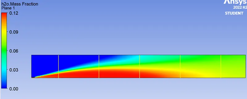
- Mass Fraction of H20 Contour:
- Mass Fraction of C02 Contour:
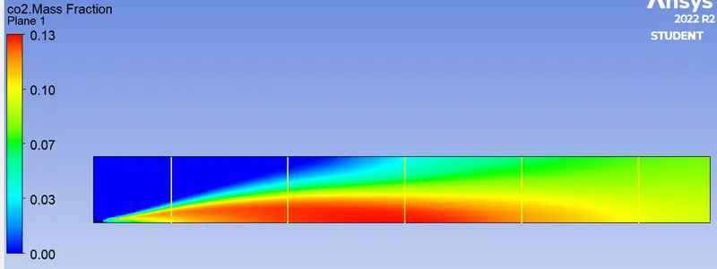
- Mass Fraction of N2 Contour:
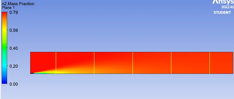
- Mass Fraction of O2 Contour:
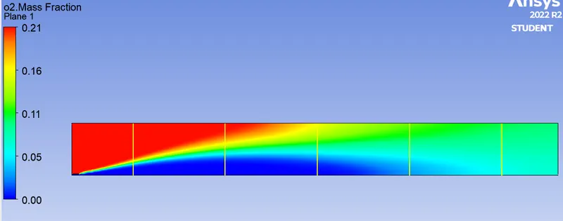
Case-c: Mass fraction of CH4 is 0.8 & H2O is 0.2
- Residual:
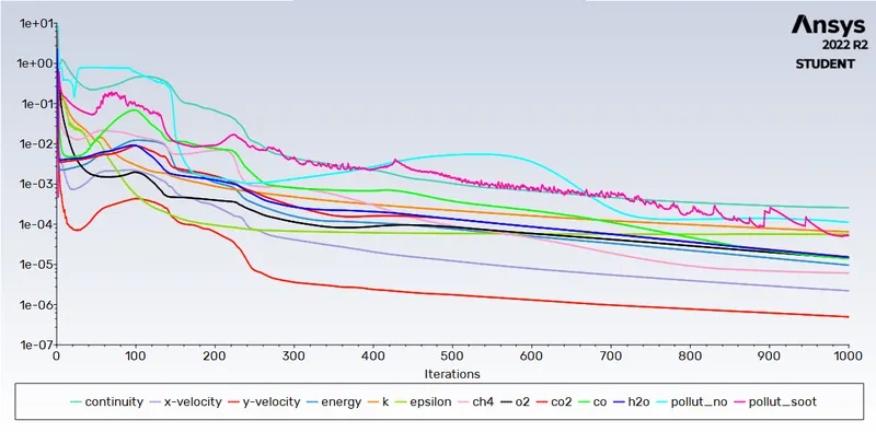
- Outlet Temperature Plot:
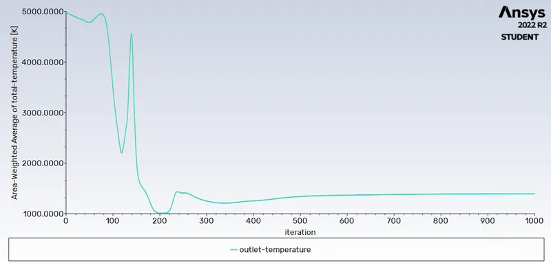
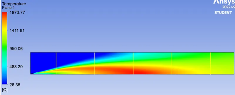
- Outlet Temperature Contour:
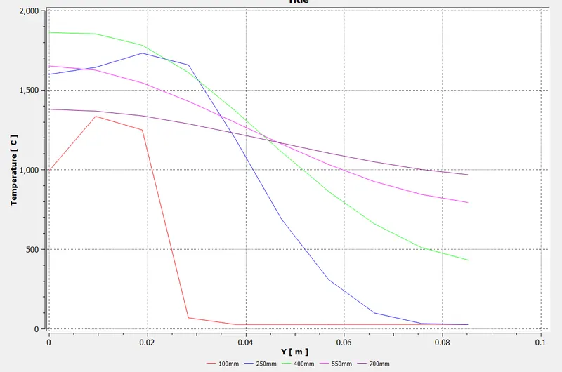
- Mass Fraction of NO Contour:
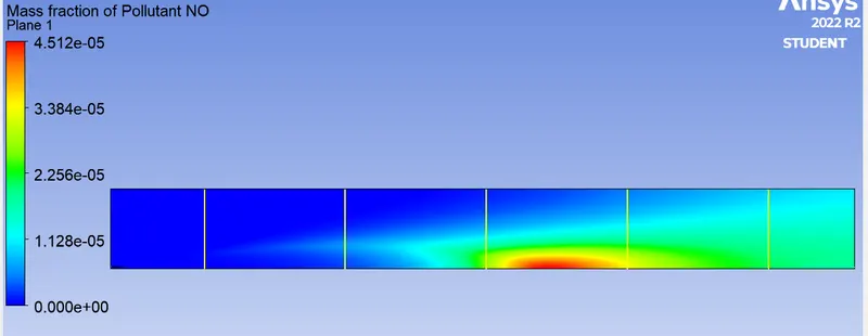
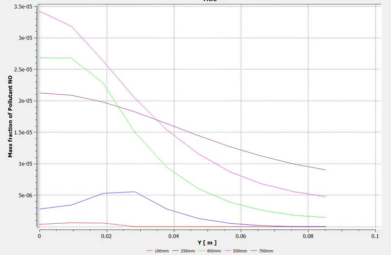
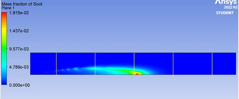
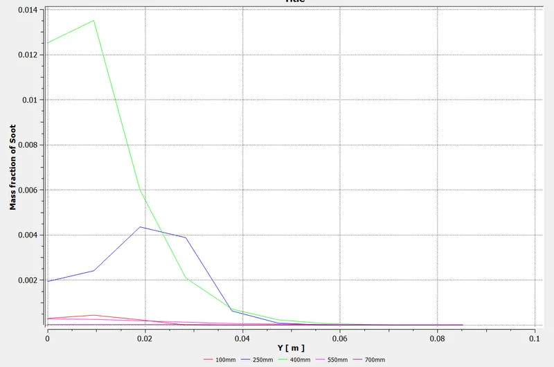
- Mass Fraction of Soot Contour:
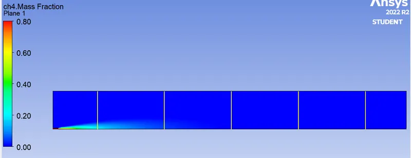
- Mass Fraction of CH4 Contour:
- Mass Fraction of H20 Contour:
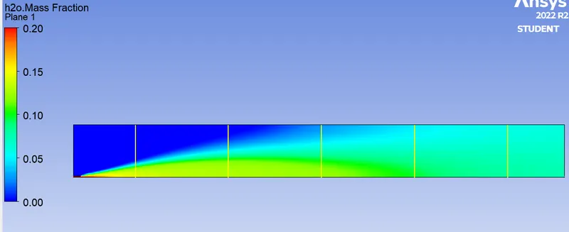
- Mass Fraction of C02 Contour:
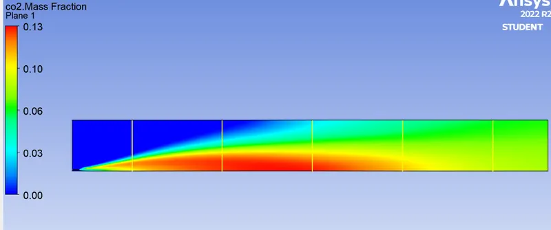
- Mass Fraction of N2 Contour:
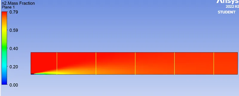
- Mass Fraction of O2 Contour:
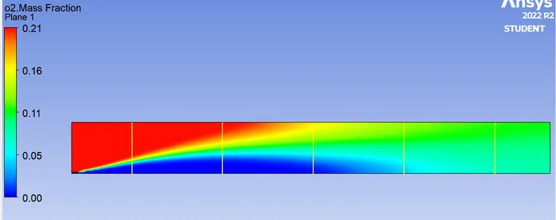
Case-d: Mass fraction of CH4 is 0.7 & H2O is 0.3
- Residual:
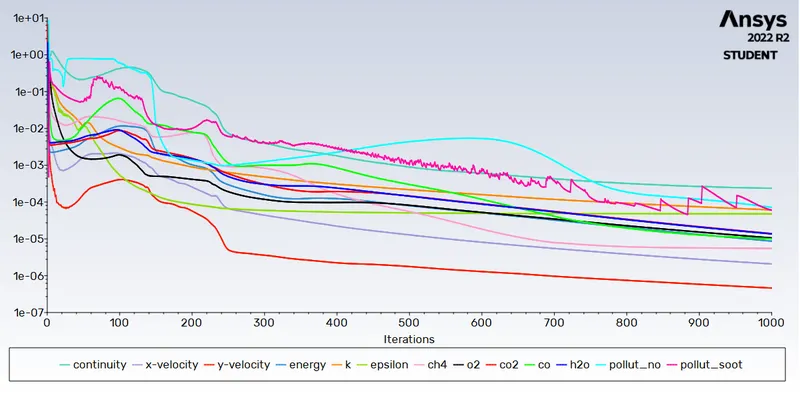
- Outlet Temperature Plot:
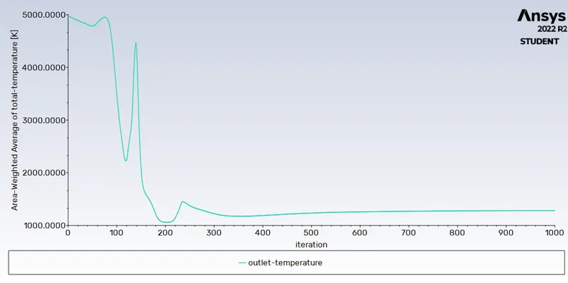
- Outlet Temperature Contour:
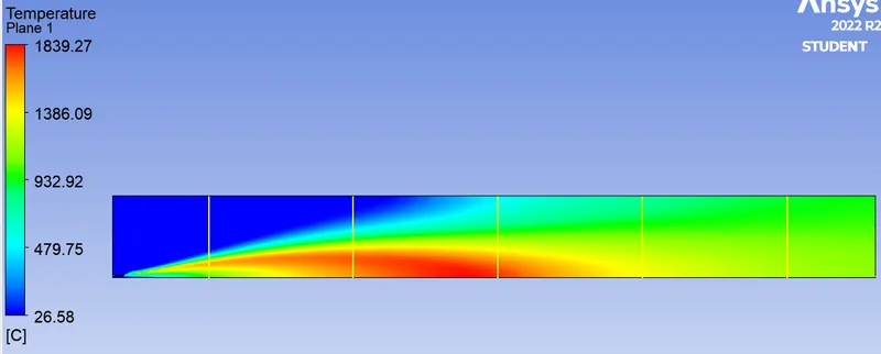
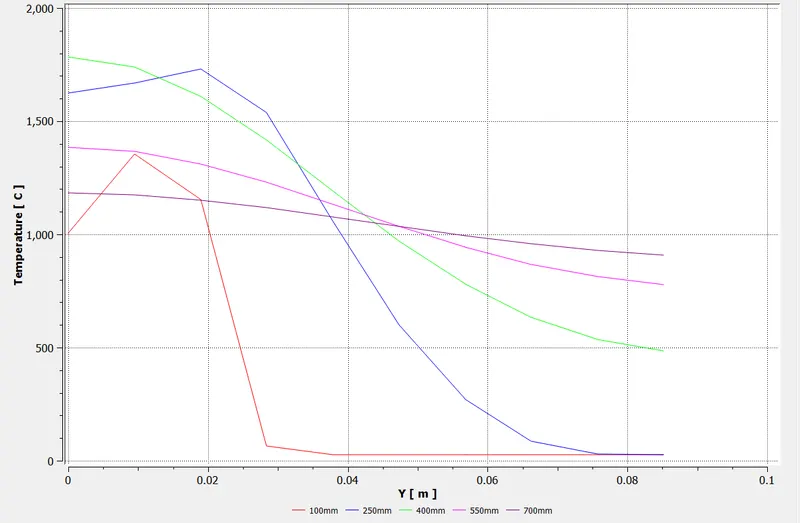
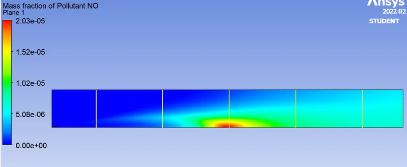
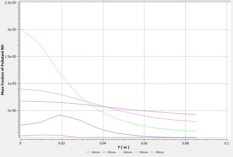
- Mass Fraction of NO Contour:
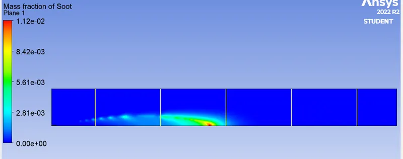
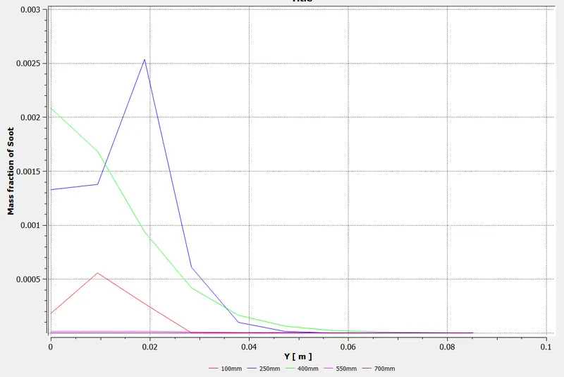
- Mass Fraction of Soot Contour:
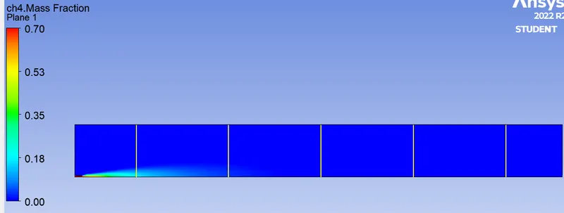
- Mass Fraction of CH4 Contour:
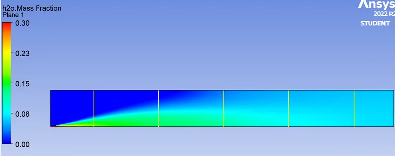
- Mass Fraction of H20 Contour:
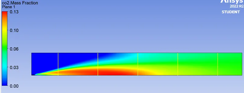
- Mass Fraction of C02 Contour:
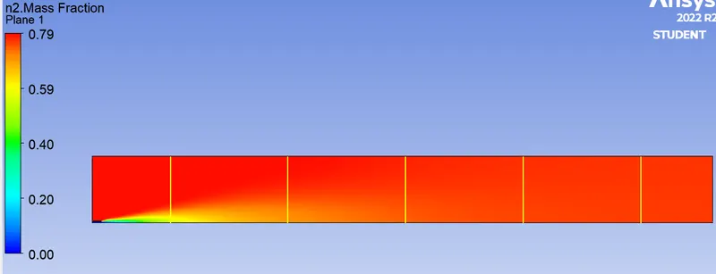
- Mass Fraction of N2 Contour:
- Mass Fraction of O2 Contour:
Result:

|
Mass Fraction of CH4 |
Mass Fraction of H2O |
Outlet Temperature (*C) |
Area Avg. Mass Fraction of NO |
Area Avg. Mass Fraction of Soot |
Max. Temperature (*C) |
Max. Mass fraction of NO |
Max. Mass fraction of Soot |
|
1 |
0 |
1334.2 |
2.5238e-5 |
0.0022952 |
1918.89 |
1.33866e-4 |
3.772e-2 |
|
0.95 |
0.05 |
1283.3 |
1.9783e-5 |
0.0017202 |
1906.81 |
9.77e-5 |
3.23e-2 |
|
0.9 |
0.1 |
1231.1 |
1.5032e-5 |
0.0014176 |
1894.74 |
7.21e-5 |
2.78e-2 |
|
0.8 |
0.2 |
1123.9 |
8.9813e-6 |
0.0007441 |
1873.77 |
4.512e-5 |
1.915e-2 |
|
0.7 |
0.3 |
1008.3 |
3.7967e-6 |
0.0003204 |
1839.27 |
2.03e-5 |
1.12e-2 |
Conclusion:
- From the simulation it is clear that as the water content in the fuel is incrased production of harmful byproduct like NOx & Soot is reduced, Eventhough these seems to be better method to reduce air pollution.
- But in order to reduce air pollution by inclusion of water in fuel we have trade of with the engine performance, as the combustion temperature is also reduced.
- By fuel dilution with H2O we can acheive complete combution, as the formation of soot is reduced.
- Eddy dissipation model helps us to model combustion via turbulence mixing without the presence of an Ignition Source.
Reference Research Paper:
1. https://www.sciencedirect.com/science/article/pii/S1876610217337724
2. https://link.springer.com/article/10.1007/s00773-015-0303-8