Week 10 - BATTERY THERMAL MANAGEMENT SYSTEM
BATTERY THERMAL MANAGEMENT SYSTEM
AIM:
- Perform the heat transfer analysis using ANSYS-Fluent software for the cylindrical
Lithium-ion Battery with heat generation boundary condition. - Create an enclosure and use air as the working fluid for cooling the battery pack system (4 x 2). (Take air inlet temperature as 300K)
OBJECTIVE:
- Run the simulation by varying the velocity of air to 3, 5, and 10m/sec and discuss
the results. - Find out the average temperature obtained by the battery.
- Vary the distance between batteries (2mm and 6mm) and run the simulation for different velocities.
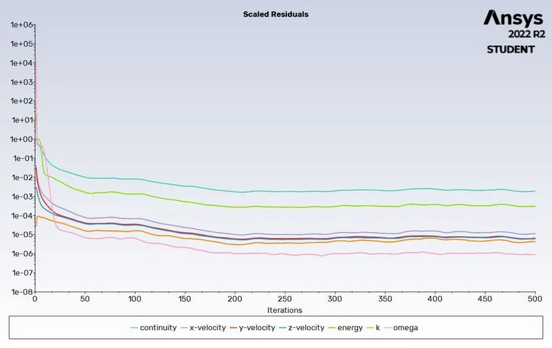
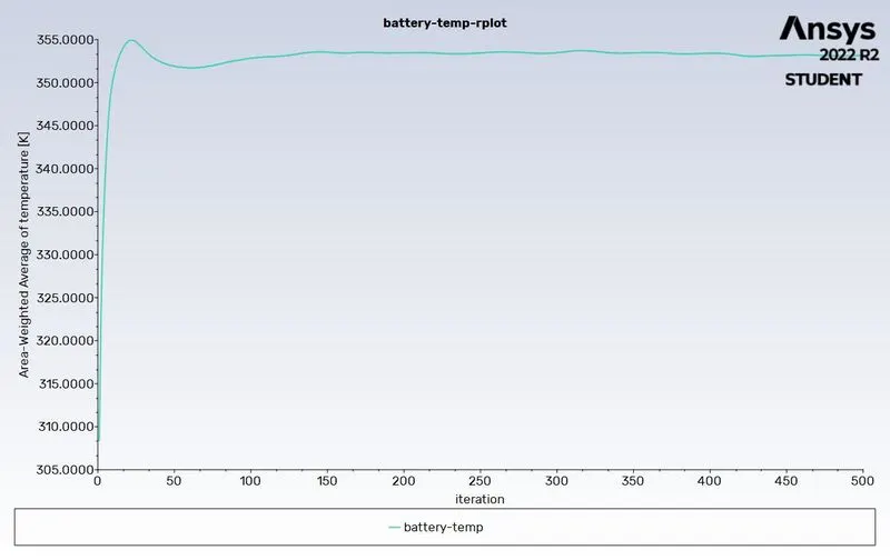
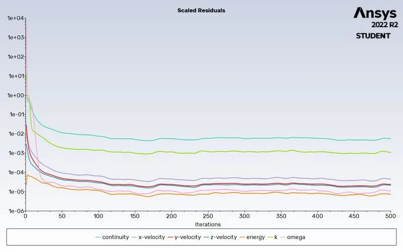
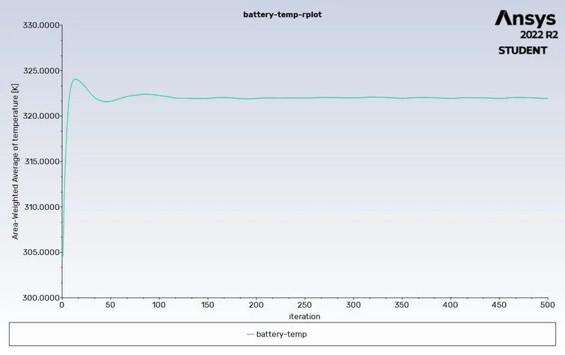
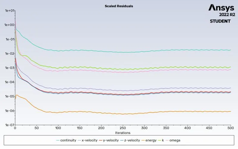
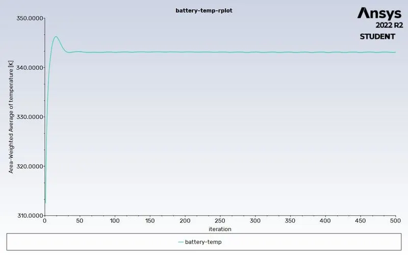
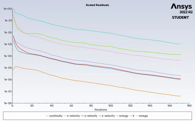
- Prove that the simulation has achieved convergence with appropriate images and
plots. - Identify potential hotspots on the model.
THEORY:
The battery unit is an integral part of the electric vehicle system. Battery units store the electricity required to drive an electric vehicle and the battery's power capacity is measured in kW. But there are some challenges related to batteries and their operation,
- High cost
- Long charging time
- Overheating
- Protection against short circuits
The last 3 issues can be mitigated if the temperature range of operation is managed under control. It will also prevent thermal runaway propagation.
Battery Thermal Management System (BTMS)
- Battery temperature varies due to the internal heat generation during the charging and discharging process.
- The uneven temperature distribution causes temperature non-uniformity, which reduces the life cycle and cell performance. It increases the chances of battery blasting.
- BTMS is required to maintain a uniform temperature distribution across the battery unit. BTMS maintains an optimal temperature range and plays a crucial role in the performance and long life of batteries.
Types of Cooling Systems
Battery cooling systems can be primarily classified into 3 different types based on the medium used.
- Liquid Cooling
- Air Cooling
- Phase Change Material (PCM)
Liquid Cooling
- Liquids have a higher heat capacity and density when compared to gases. This results in a higher convective heat removal rate.
- Liquid coolant systems are more compact and have less power consumption when compared to air cooling systems,
- It produces less noise
- But there is always a chance of leakage while dealing with liquid cooling systems.
- Liquid cooling can be done in 2 ways, direct cooling, and indirect cooling.
- In direct cooling, the entire surface area of the cell is covered and uniform temperature is maintained. It removes any hotspots and improves battery life. It is mainly used in data center servers. Due to the risk of short circuits, this method is not used in electric vehicles.
- Indirect cooling aims at avoiding electrical conduction within the cells while maintaining high thermal diffusion. In this method, cold plates, water jackets, and heat pipes are used to dissipate heat effectively. All connections to the coolant are kept outside to eliminate the risk of leakage. This method is used by car manufacturers like General Motors and Tesla.
Air Cooling
- Air is used as a cooling medium mainly due to its easy availability and low maintenance costs.
- The cooling is done either by natural convection(passive cooling) or forced convection(active cooling). Passive cooling is suitable only for low-density batteries, and typically blowers or fans are used to enhance the convection heat transfer rate. The batteries near the outlet will show higher temperatures when compared to the ones near the inlet. Therefore care must be taken while designing the layout of batteries. The flow rate and turbulence of the airflow should be selected to ensure uniform cooling. This type of cooling is used by car manufacturers like Honda, Nissan, and Toyota.
Phase Change Material (PCM)
- Due to high latent heat PCM absorbs heat significantly more than normal materials.
- A solid-to-liquid phase change material is put next to the cells.
- Paraffin mixed with graphite flakes has a melting point of 32 to 38-degree celsius making it suitable for electric vehicles.
- Graphite flakes are used to increase thermal conductivity. It also acts as a semi-matrix block which will contain the paraffin.
- PCM acts as a shield, in case one cell undergoes thermal runaway.
MODELLING APPROACH:
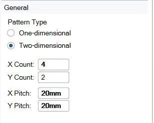
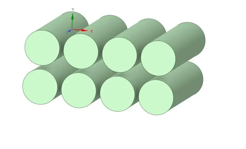
- A battery pack system of 8 batteries (4x2) is considered for this study.
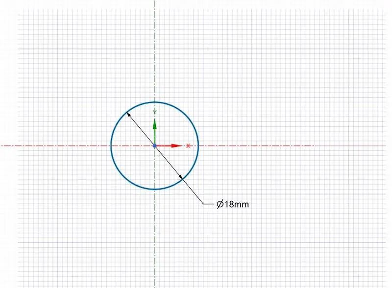
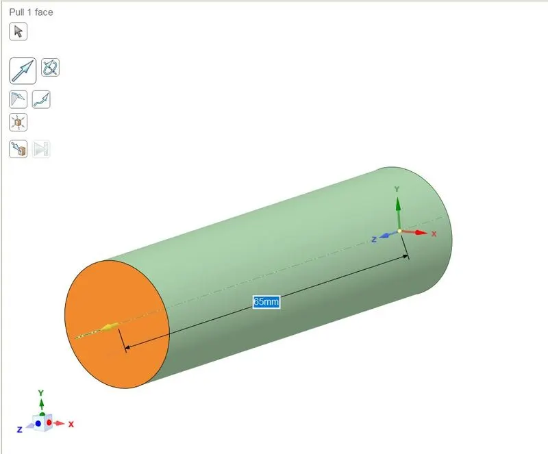
- Size of the Battery = 18 mm diameter and 65 mm height.
- An enclosure is created and the working medium is selected as air.
- Heat Generation per battery is taken as 10 W and the heat generation boundary condition is assigned.
- K omega standard turbulence model is used as the flow is turbulent.
- The material for the battery is selected as Lithium
PREPROCESSING:
Geometry
- Open Spaceclaim and select Sketch mode
- Draw a circle of diameter 18mm.
- Using the Pull tool, extend the circle in the z-direction by 65mm to get a cylinder.
- Use the pattern option under the Design tab to create a 4x2 battery layout.
- Create an enclosure using the Enclosure tool under the Prepare tab.
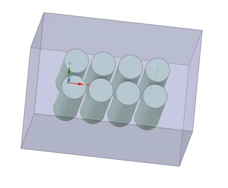
- Use the Share tool to share coincident topology
Meshing
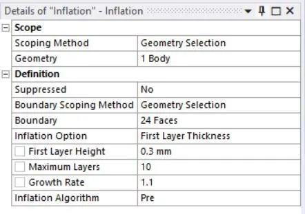
- Generate mesh with a mesh element size of 5mm
- Add Inflation layers between the batteries and fluid domain
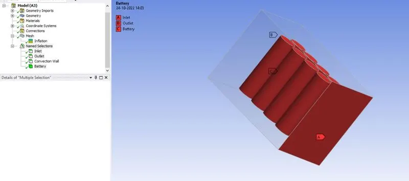
- Using the Create Named Selection option, assign appropriate names to the boundaries.
Fluent Setup
| 1. | Solver Type | Pressure based |
| 2. | Solver Time | Steady State |
| 3. | Viscous Model | K omega standard |
| 4. | Energy | ON |
| 5. | Material (Fluid) | Air |
| 6. | Material (Solid) |
Lithium for batteries Aluminium for wall |
| 7. | Inlet | Velocity inlet (3,5, and 10 m/s) |
| 8. | Outlet | Pressure based |
| 9. | Convection wall | Convection with heat transfer coefficient of 5 W/m^2.K |
| 10. | Method | Coupled |
- As Lithium is not present in the Fluent database, we need to create a new material and assign it the properties of Lithium
Density = 2700 kg/m3
Specific heat = 900 J/kg.K
Thermal Conductivity = 7.14 W/m.K
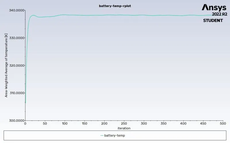
- Create a report definition for the average temperature on the battery.
- After hybrid initialization, the simulation is run for 500 iterations.
- One case of simulation is done for the transient case, to analyze the intermediate stages. In this case, the gap between cells is 2mm and the inlet velocity is 5 m/s.
RESULTS:
2mm gap between batteries
Inlet velocity of 3m/s
- Residuals
- Average Battery temperature
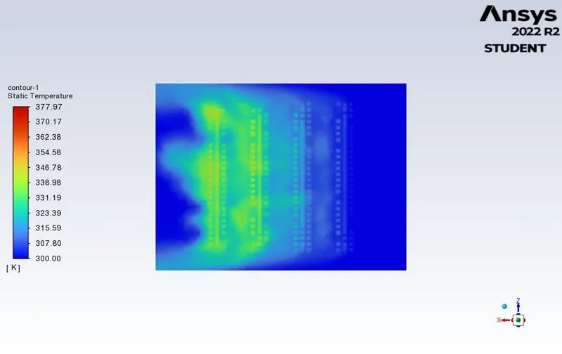
- Temperature contour (XZ plane)
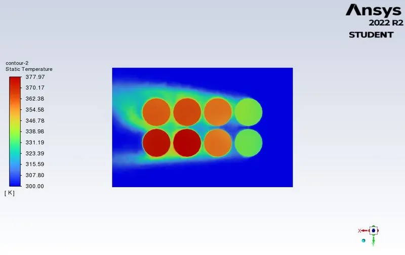
- Temperature contour (XY plane)
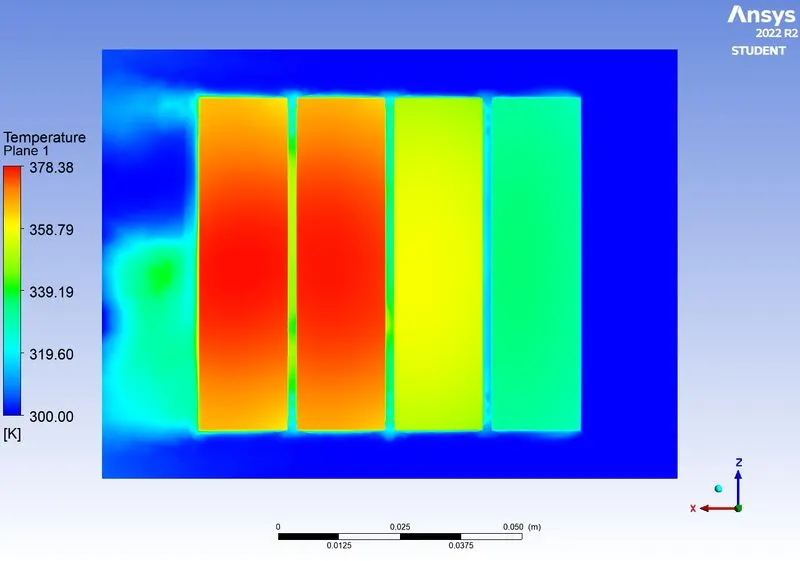
- Temperature contour (YZ plane)
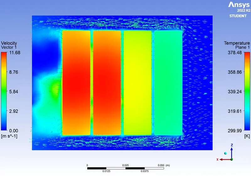
- Velocity contour
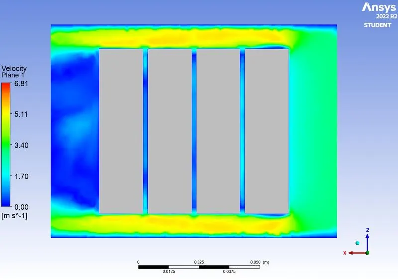
- Velocity vector
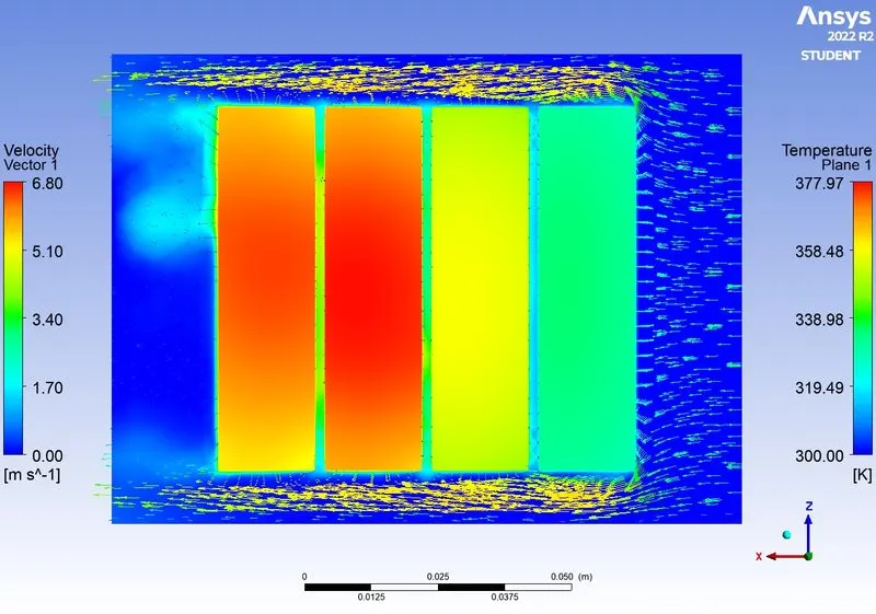
- Temperature contour after 1 iteration
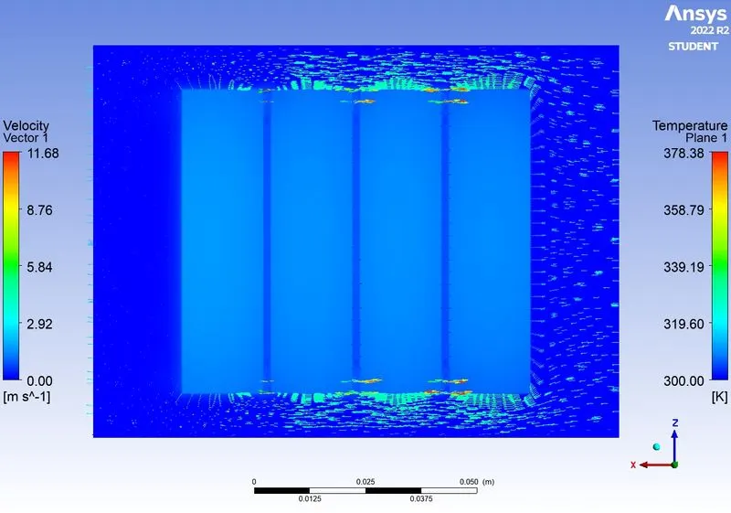
- Temperature contour after 100 iterations
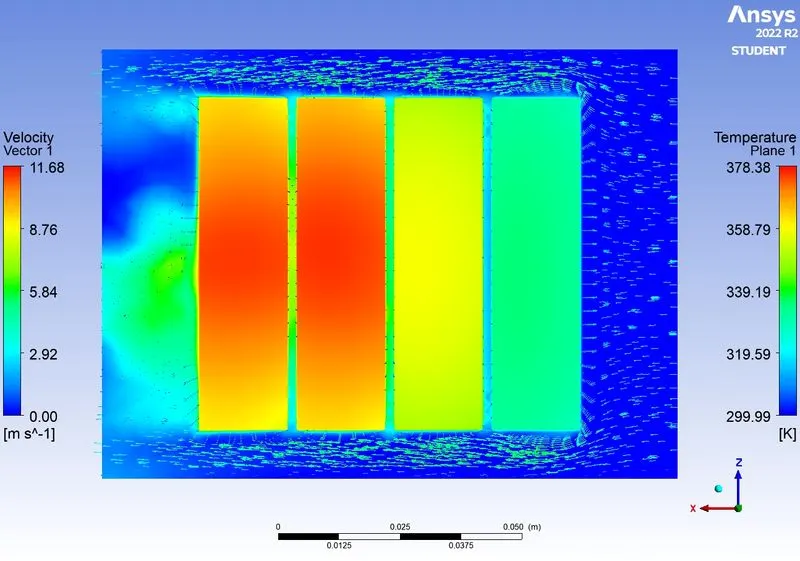
- Temperature contour after 250 iterations
- Animation video - Please refer to the attached RAR file
Inlet velocity of 5m/s
- Residuals
- Average Battery temperature
- Temperature contour (XZ plane)
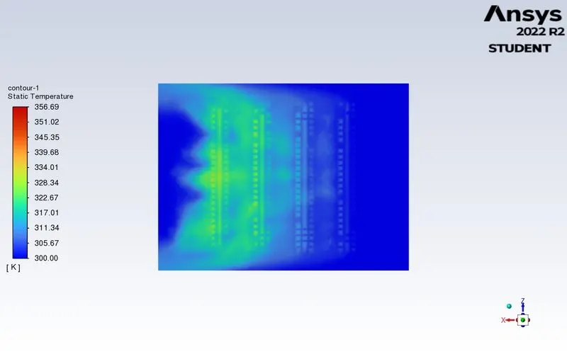
- Temperature contour (XY plane)
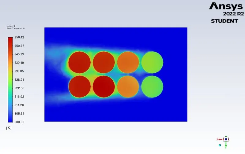
- Temperature contour (YZ plane)
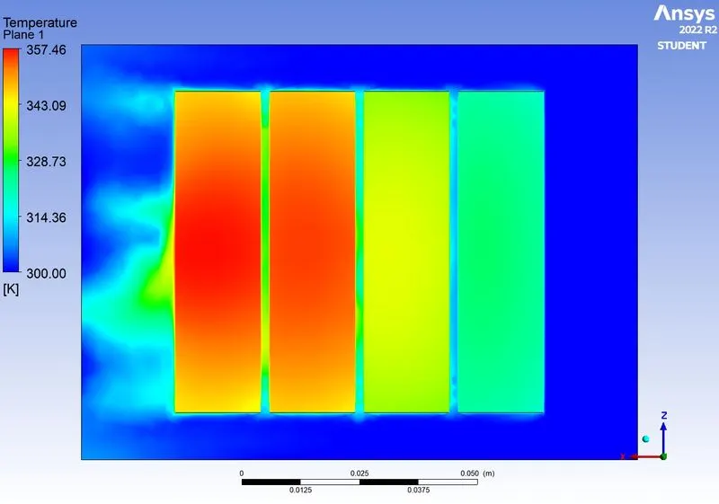
- Velocity contour
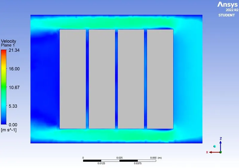
- Velocity vector
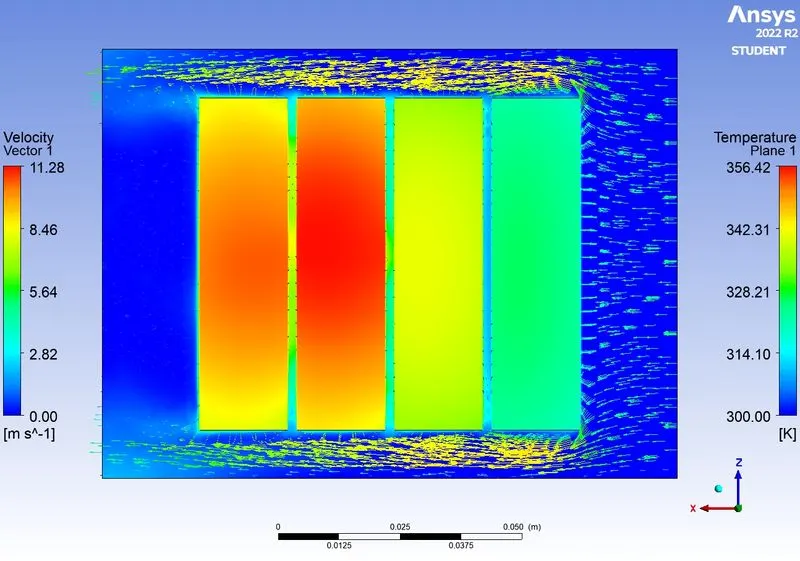
- Temperature contour after 1 iteration
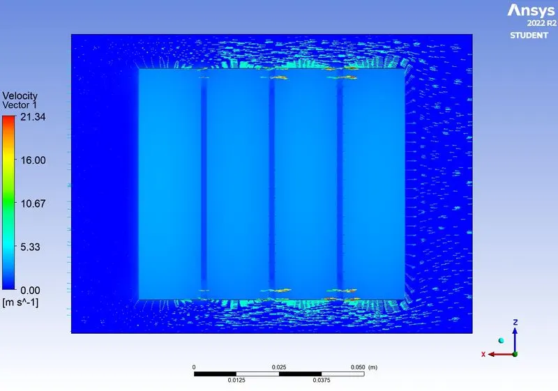
- Temperature contour after 100 iterations
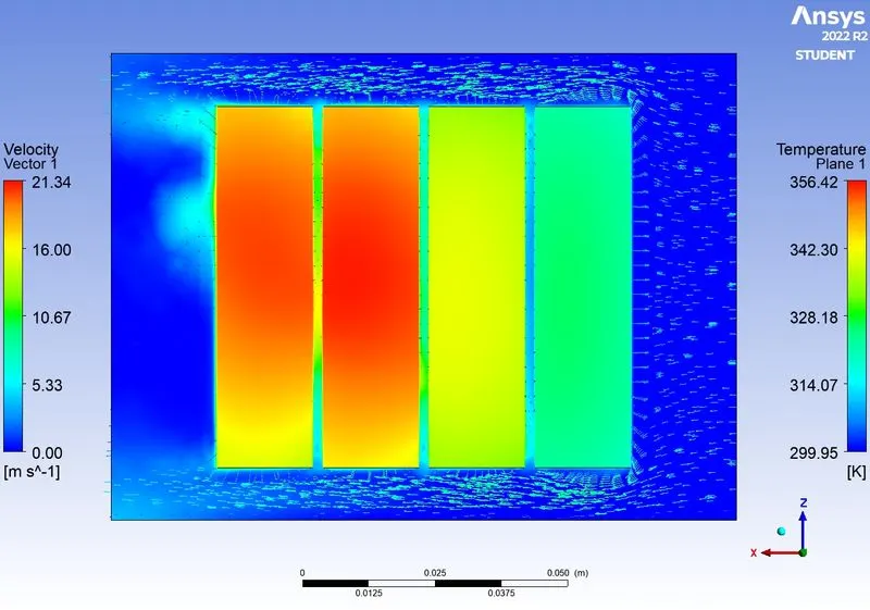
- Temperature contour after 250 iterations
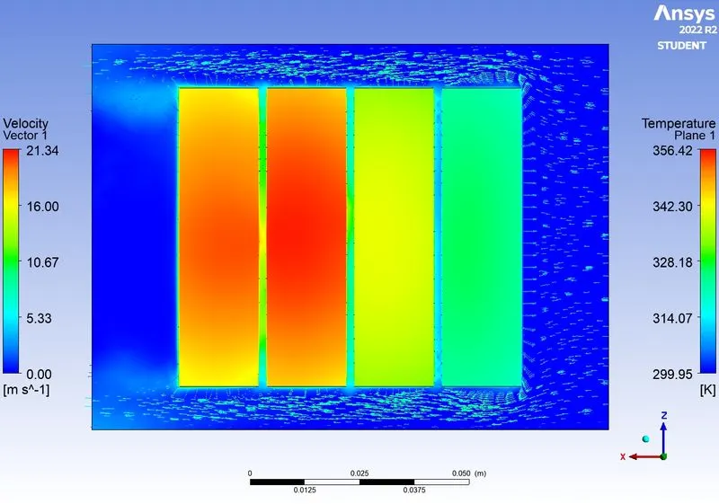
- Animation video - Please refer to the attached RAR file
Inlet velocity of 10m/s
- Residuals
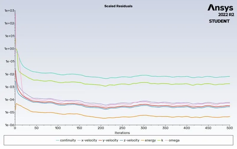
- Average Battery temperature
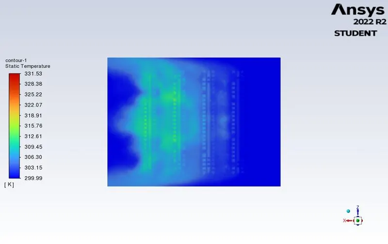
- Temperature contour (XZ plane)
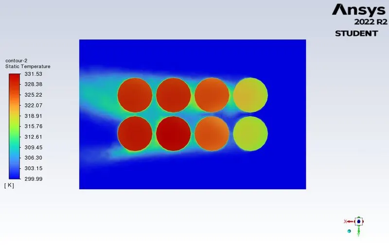
- Temperature contour (XY plane)
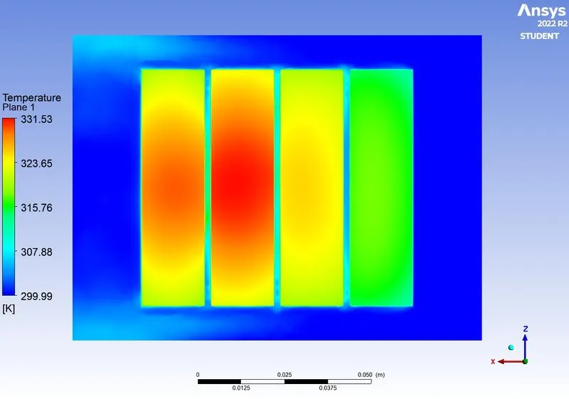
- Temperature contour (YZ plane)
- Velocity contour
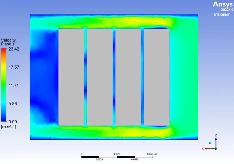
- Velocity vector
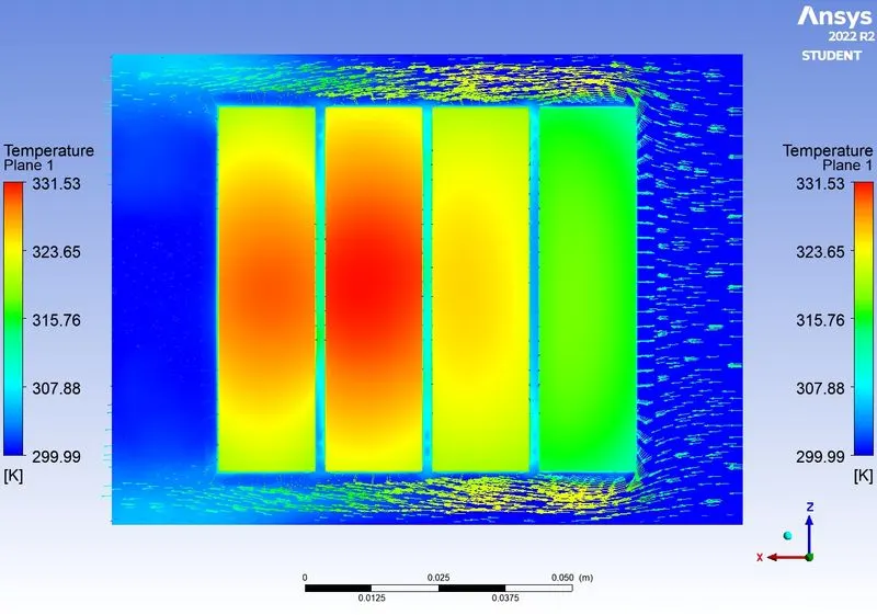
- Temperature contour after 1 iteration
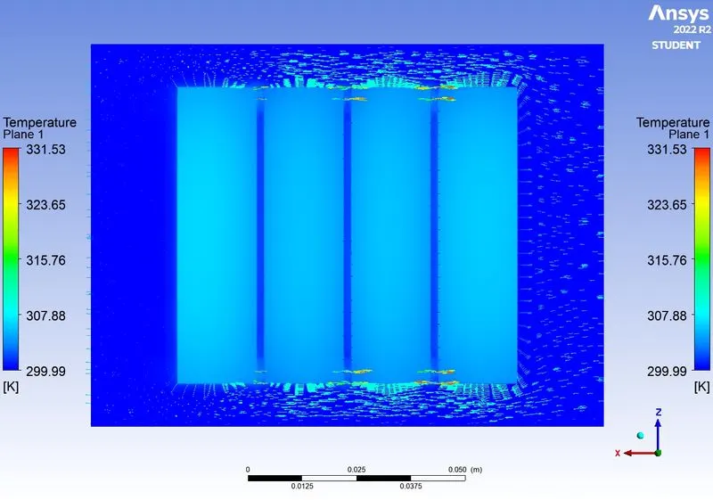
- Temperature contour after 100 iterations
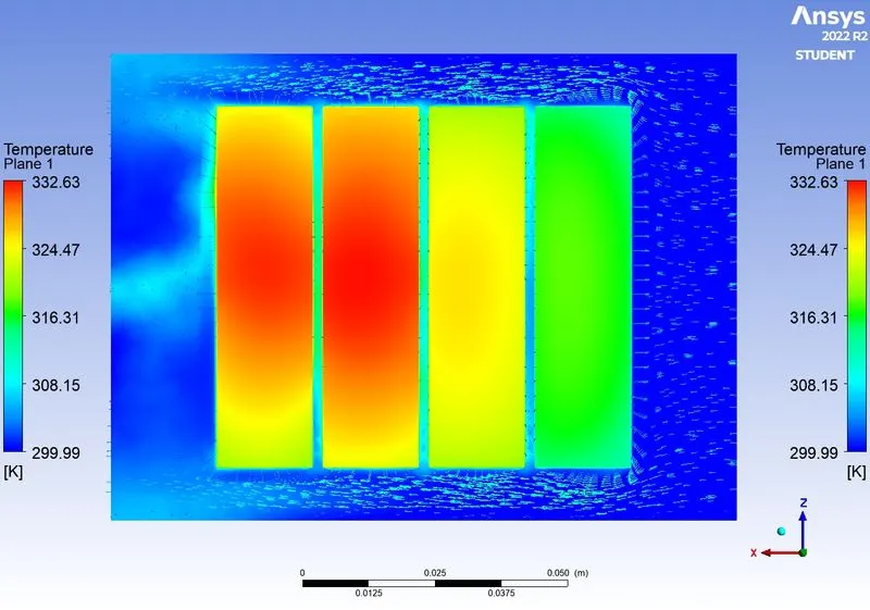
- Temperature contour after 250 iterations
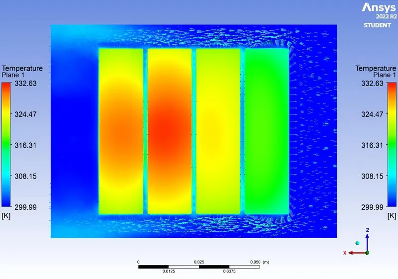
- Animation video - https://drive.google.com/file/d/1rYgRZ-12TM5diaZ9DMc5Ka9dZ6E8p2g5/view?usp=sharing
6mm gap between batteries
Inlet velocity of 3 m/s
- Residuals
- Average Battery temperature
- Temperature contour (XZ plane)
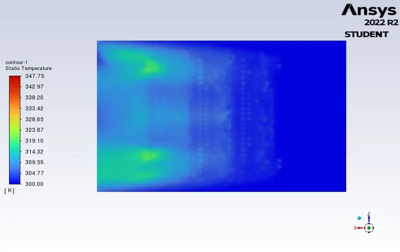
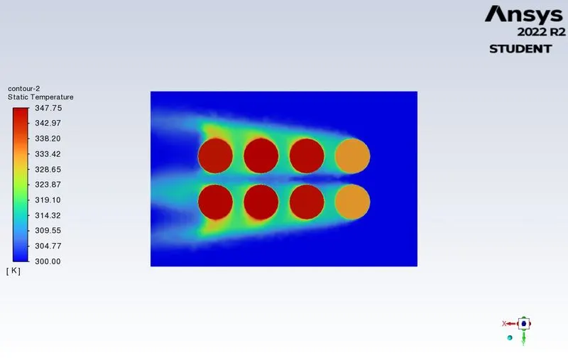
- Temperature contour (XY plane)
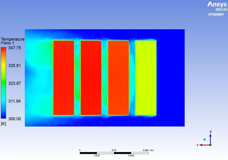
- Temperature contour (YZ plane)
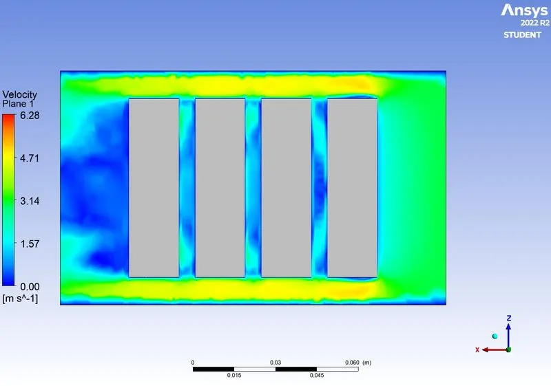
- Velocity contour
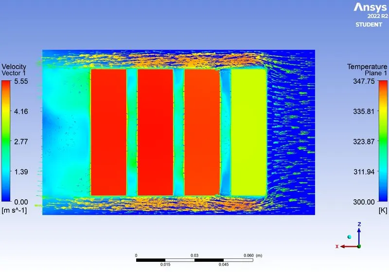
- Velocity vector
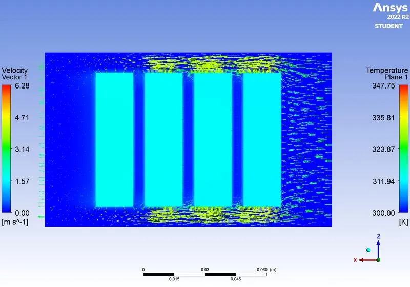
- Temperature contour after 1 iteration
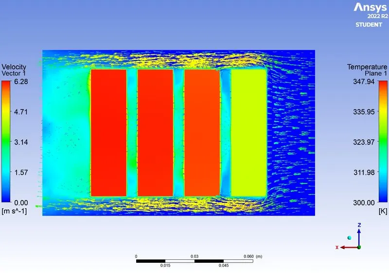
- Temperature contour after 100 iterations
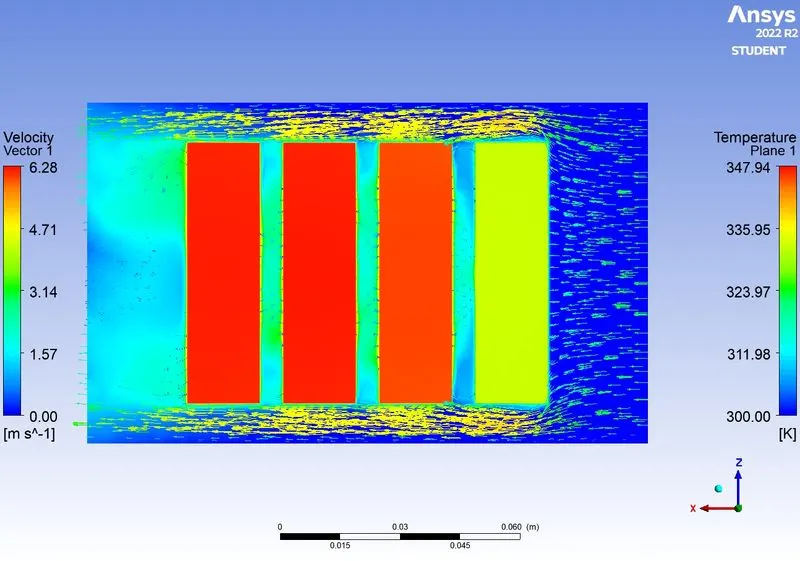
- Temperature contour after 250 iterations
- Animation video - Please refer to the attached RAR file
Inlet velocity of 5m/s
- Residuals
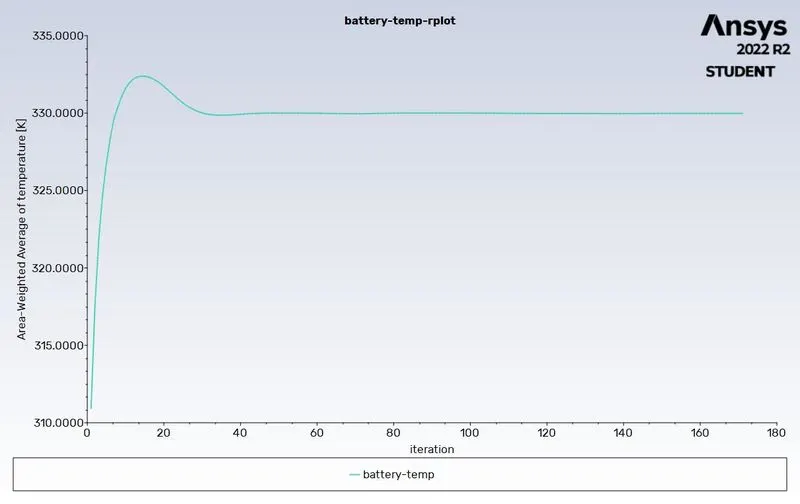
- Average Battery temperature
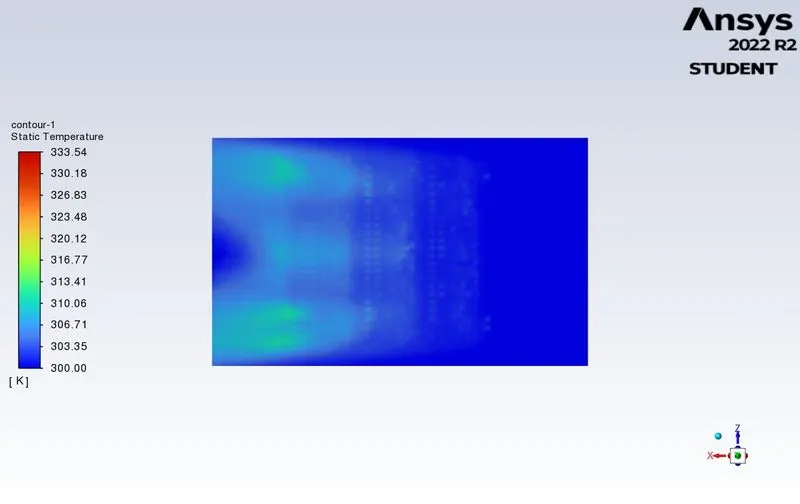
- Temperature contour (XZ plane)
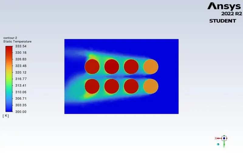
- Temperature contour (XY plane)
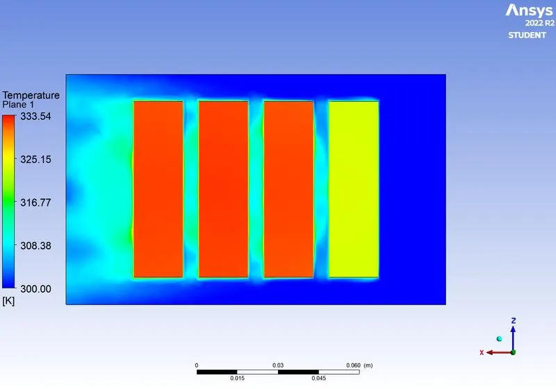
- Temperature contour (YZ plane)
- Velocity contour
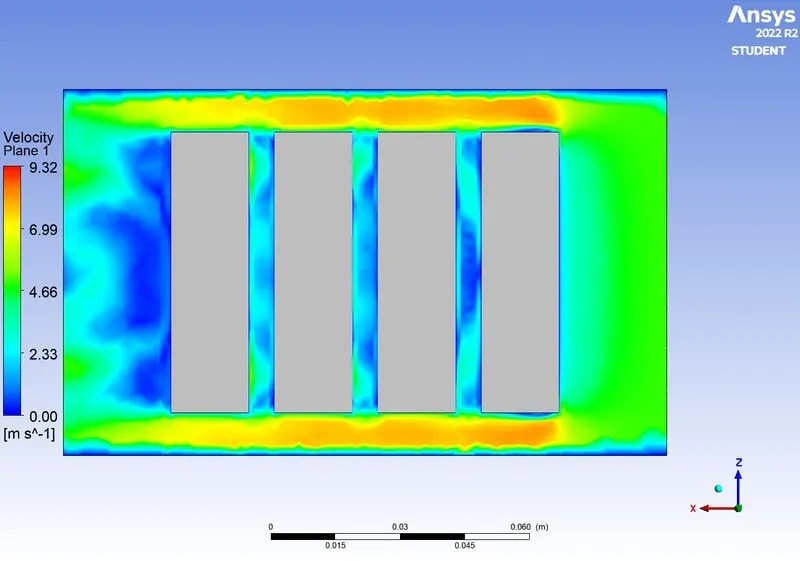
- Velocity vector
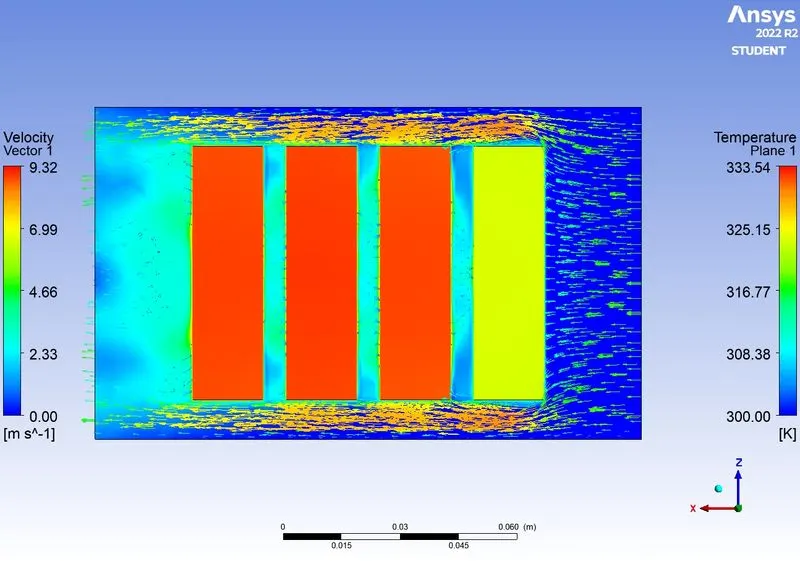
- Temperature contour after 1 iteration
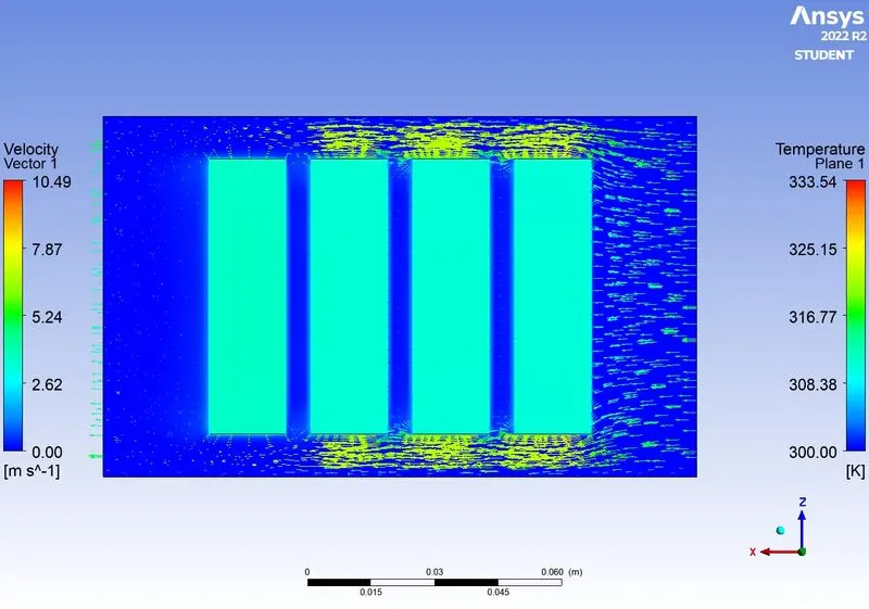
- Temperature contour after 100 iterations
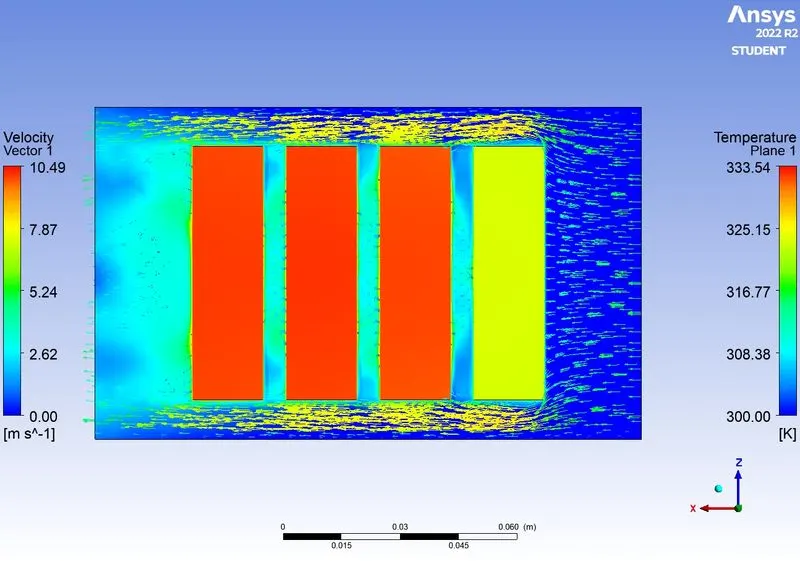
- Temperature contour after 150 iterations
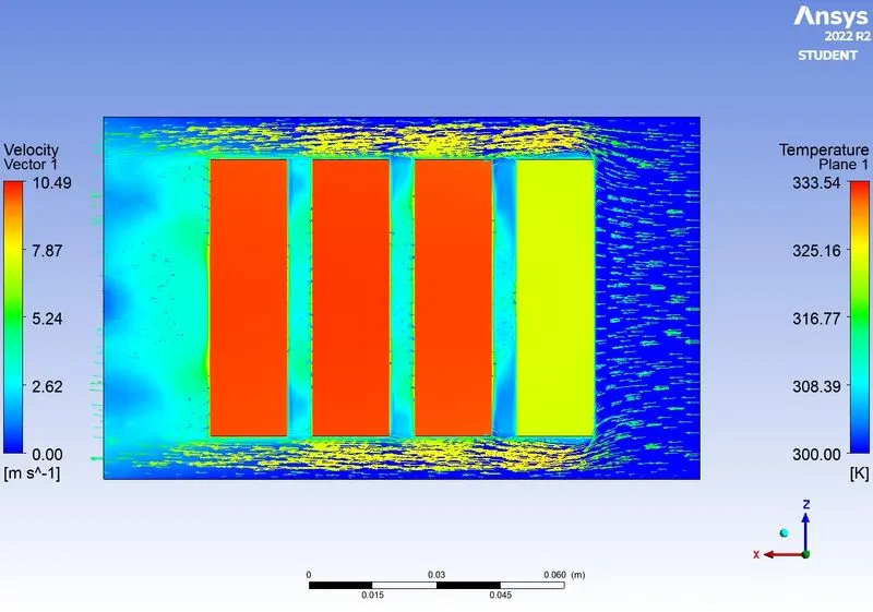
- Animation video - https://drive.google.com/file/d/1J0DmjaVh1vBMnY7Ft_50Zo75i_lfcFlo/view?usp=sharing
Inlet velocity of 10m/s
- Residuals
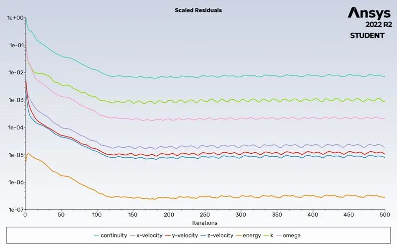
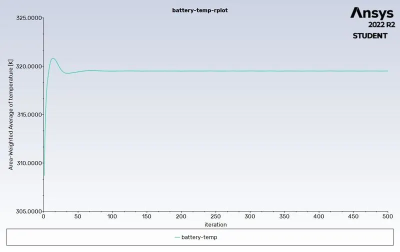
- Average Battery temperature
- Temperature contour (XZ plane)
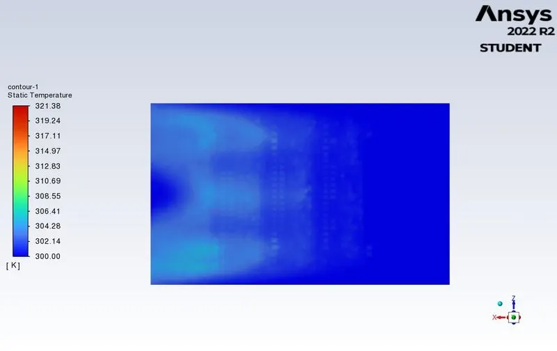
- Temperature contour (XY plane)
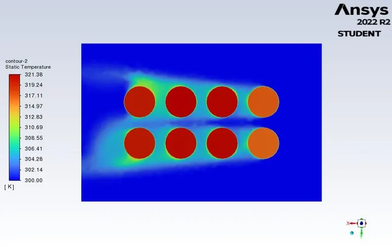
- Temperature contour (YZ plane)
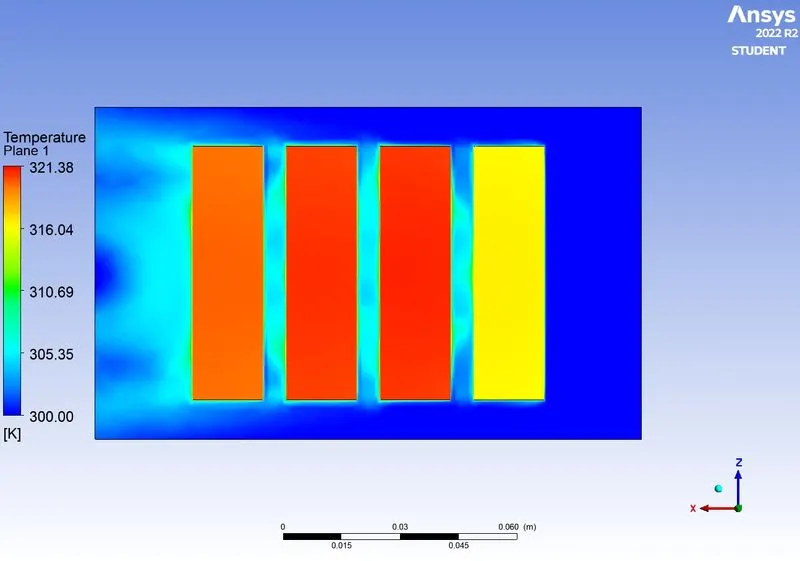
- Velocity contour
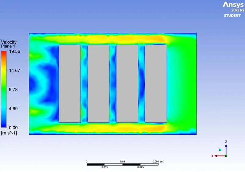
- Velocity vector
- Temperature contour after 1 iteration
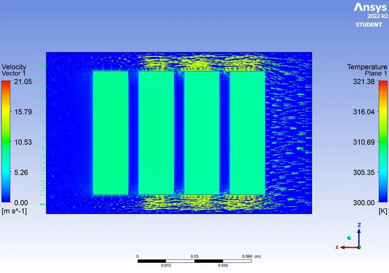
- Temperature contour after 100 iterations
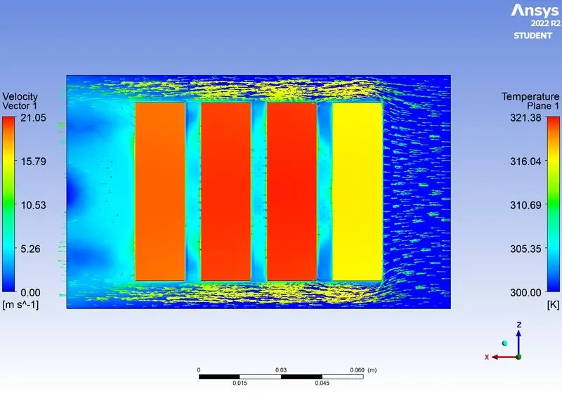
- Temperature contour after 250 iterations
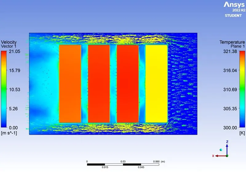
- Animation video - https://drive.google.com/file/d/1v46wWdYh3BRLO5IfJRuraP11KIHt-g9M/view?usp=sharing
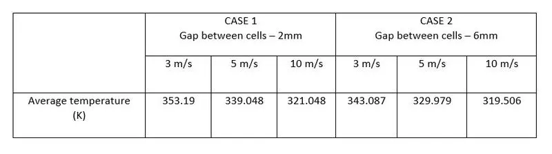
Average Temperature Comparison
Transient state simulation
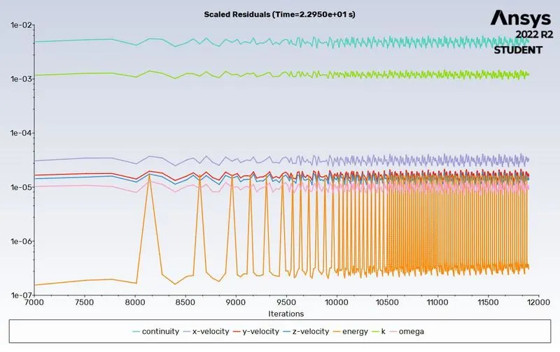
- Residuals
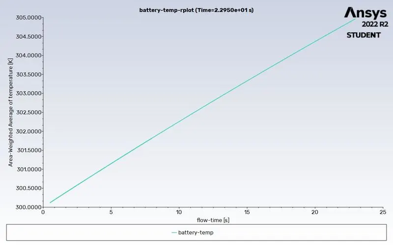
- Average Battery temperature
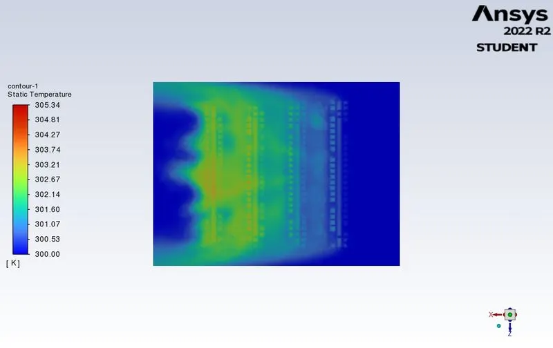
- Temperature contour (XZ plane)
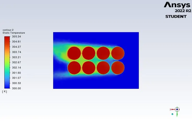
- Temperature contour (XY plane)
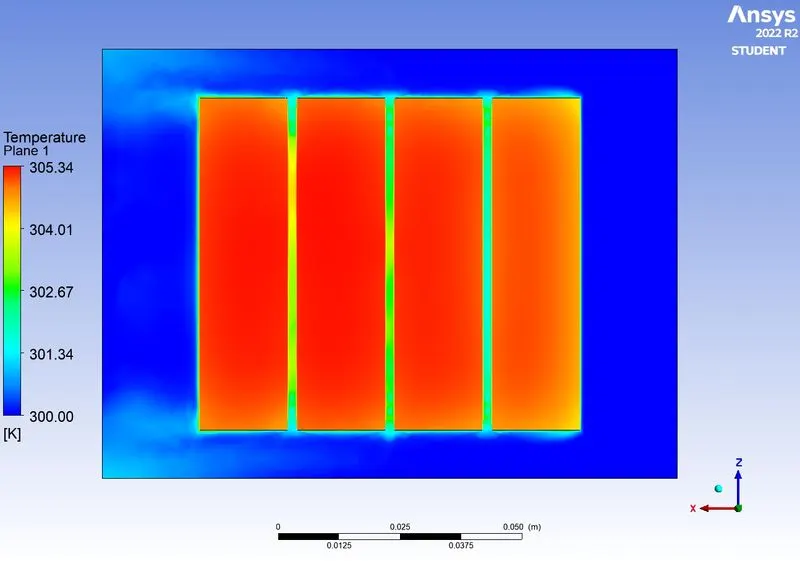
- Temperature contour (YZ plane)
- Velocity contour
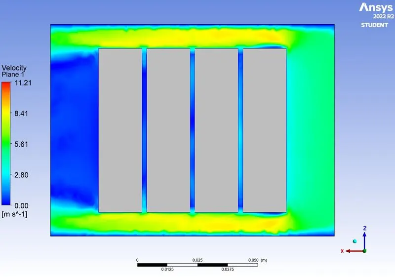
- Velocity vector
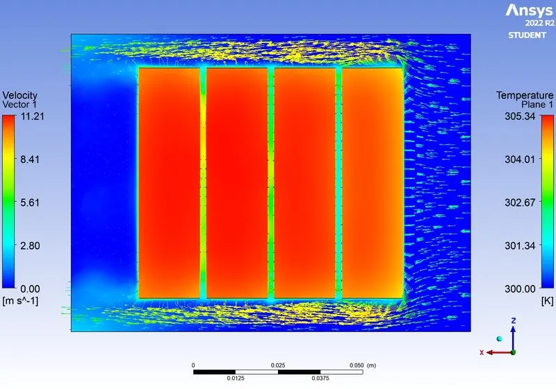
- Animation video - https://drive.google.com/file/d/1ibg7H-Jodeh5kLqnQyJdkME1v2yS9OBB/view?usp=sharing
CONCLUSIONS:
- The batteries situated near the inlet are maintained at a much lower temperature than the ones near the outlet.
- For the same gap between batteries, we can observe that with higher velocity, the average temperature decreases.
- The average temperature values are less when the gap is 6mm compared to 2mm.
- The results from the transient simulation were inconclusive, but the animation video gives us an idea about the intermediate stages of cooling.