Week 10 - Simulating Combustion of Natural Gas.
The aim of this exercise is to perform a combustion simulation of a combustor model and to plot the variation of mass fraction for different species. Also, The simulation is repeated with the addition of water in specified quantities to analyse the effect on the results.
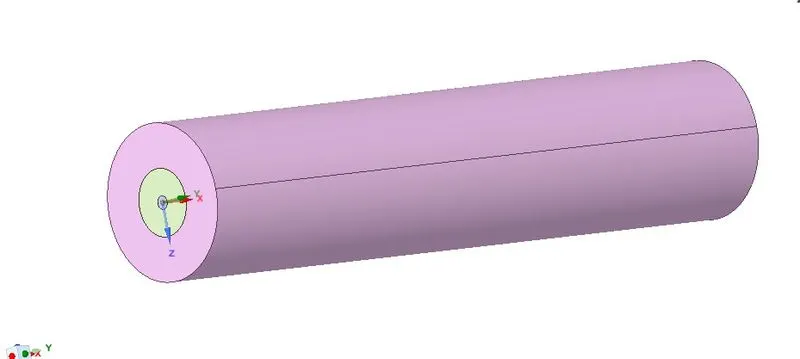
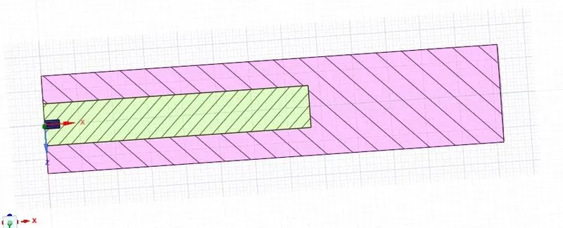
For this simulation, first, we are going to create a combustor model and then import the model into spaceclaim. There, from the solid model, we are going to split hte body using splitbody command and then, create a plane in which the body has to be split. Then, we select the surfaces needed for simulation and then copy the surfaces and paste in a new design. Now, we use combine command to merge all the surfaces into one for simulation.
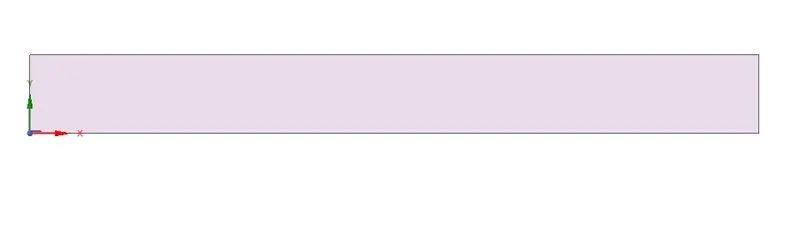
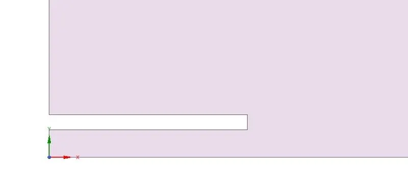
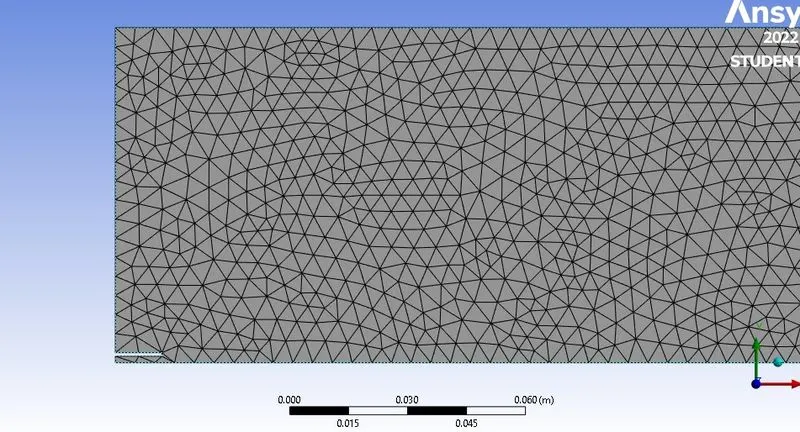
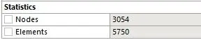
Now, we save the model and import into mesh for meshing the geometry. In meshing, we first create named selections for the 2 inlet namely air and fuel inlets, outlet, walls, axis. Then, we insert the mesh size, and then insert method for triangular mesh and sizing parameter for the mesh size as 5 mm. Now, we generate the mesh.
Now, we enter fluent where we set the parameters and boundary conditions reuired for the simulation.
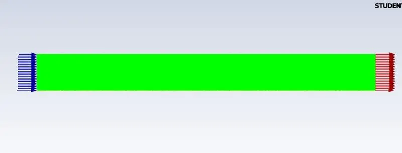
In fluent, we first set the parameters and boundary conditions. First, we use steady state, pressure based, density and absolute velocity formation with axissymmetry and energy equation enabled. Now, we choose the k-epsilon viscous turbulent model and under species, we choose methane air as the mixture we need. Now, under species model, we choose species transport with volumetric reactions and inlet diffusion and diffusion energy source checked. We also choose eddy-dissipation for turbulence chemistry dissipation.
Now, under models, we choose NOx and select thermal and prompt NOx with the fuel stream and for soot model, we choose One-setp, with fuel as CH4 anbd oxidant as O2.
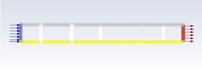
Now, for the boundaries, we first choose the air inlet and specify the velocity as 0.5m/s and the temperature as 300K and under species we choose the value for mass fraction for O2 as 0.23.
For the fuel inlet, we choose the inlet velocity as 80m/s and under species, we specify the value for CH4 as 1.The walls are set for temperature of 300K.
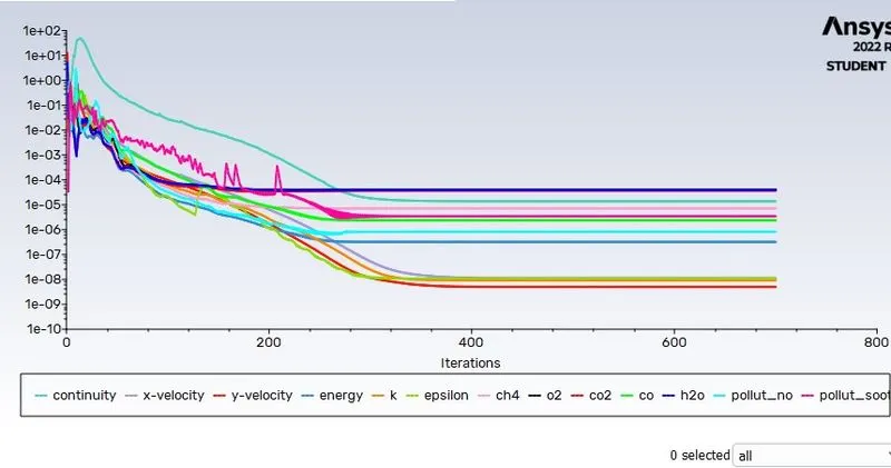
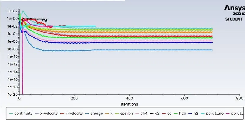
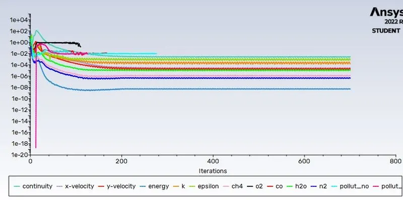
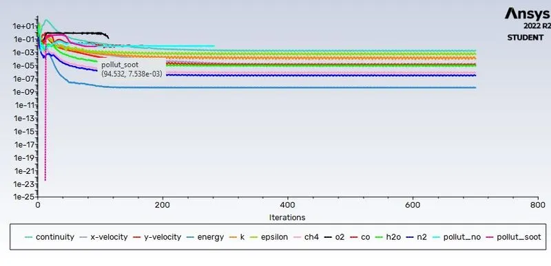
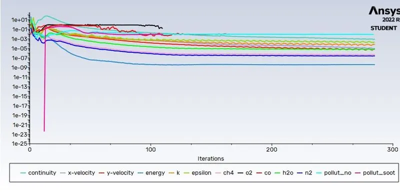
We initialize the solution using hybrid initialization method and then add the necessary contours such as the temperature, and the mass fraction contours for the species while creating a solution animation for the contour plot desired. Now we run the solution for 700 iterations.
Case 1:
Case 2:
5% H20:
10% H20:
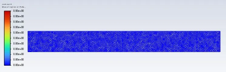
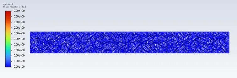
For 15% H2O:
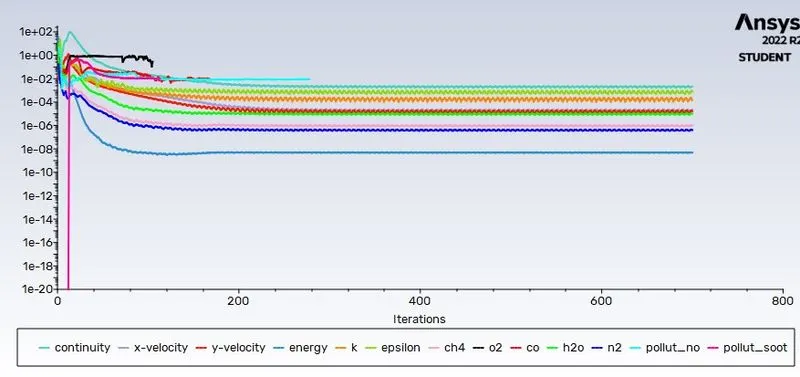
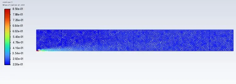
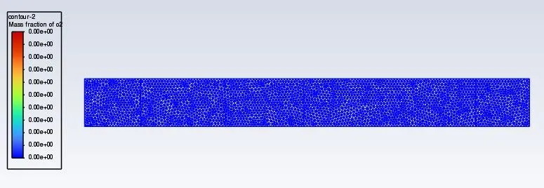
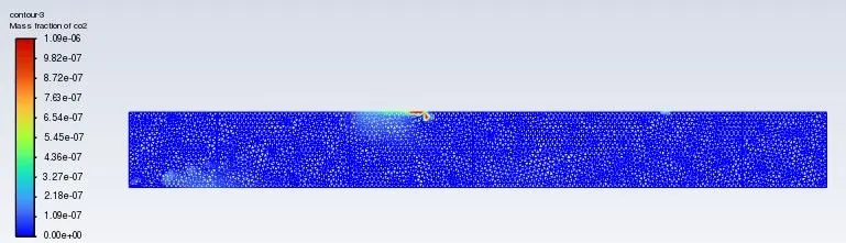
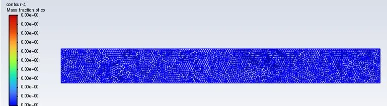
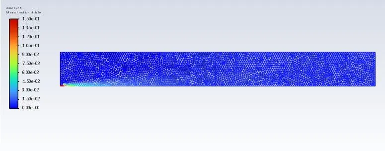
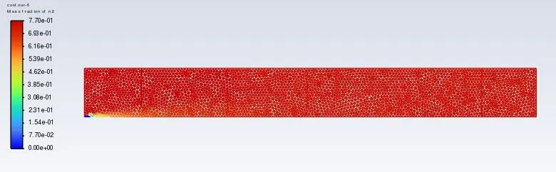
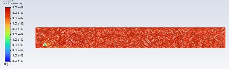
For 20% H2O:
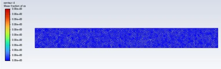
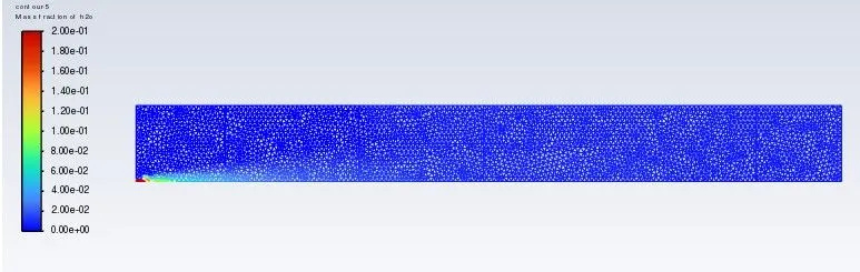
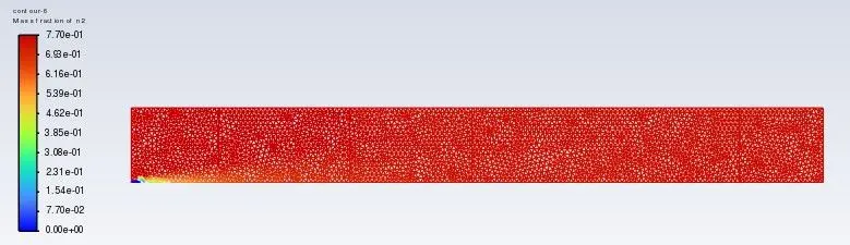
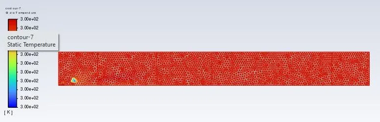
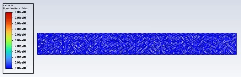
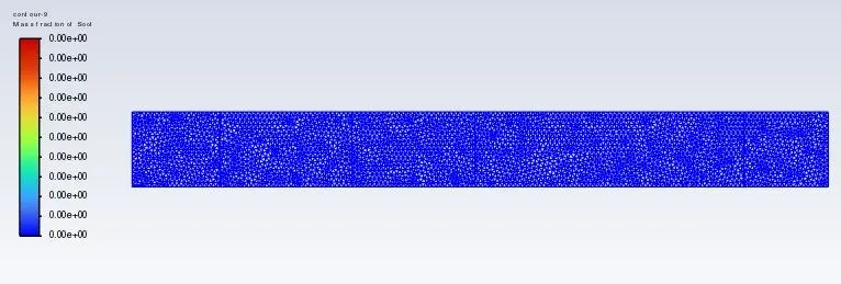
For 25% H2O
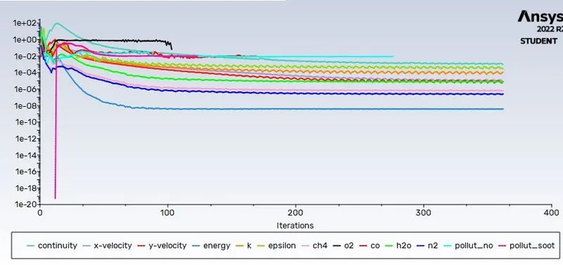
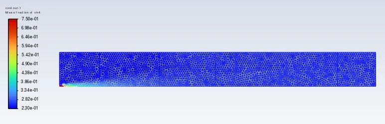
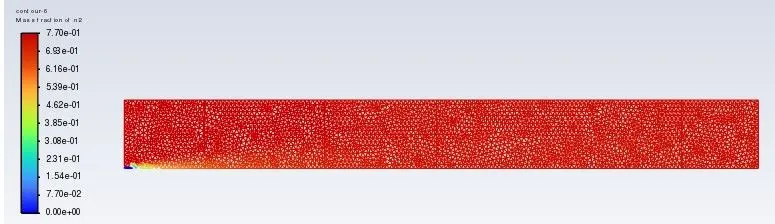
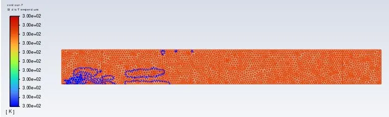
For 30% H2O:
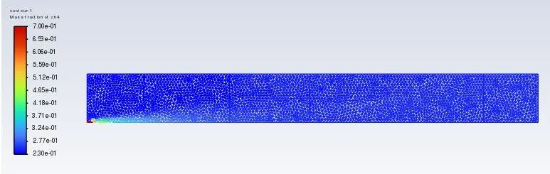
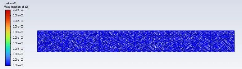
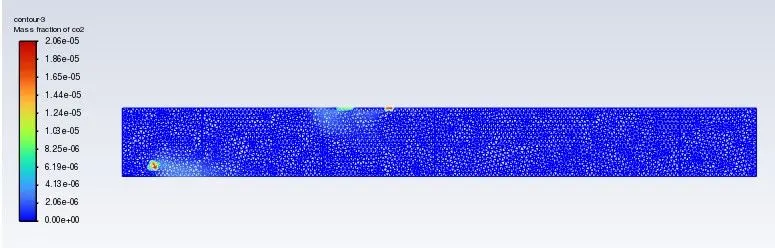
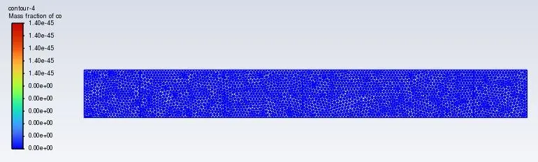
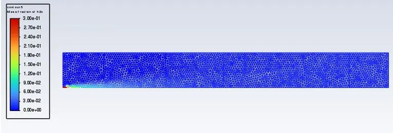
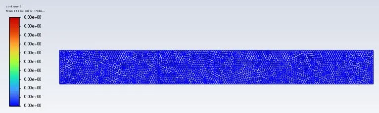
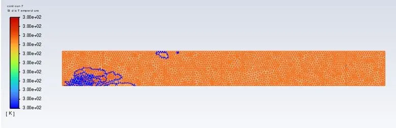
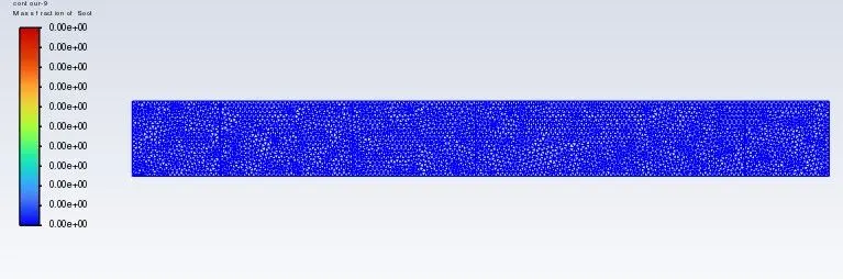
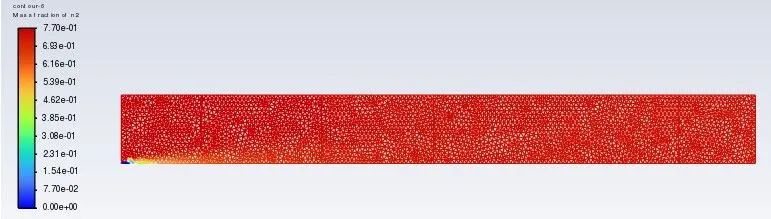
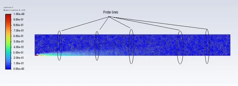
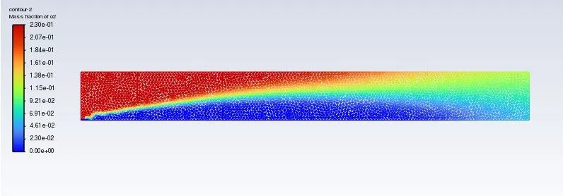
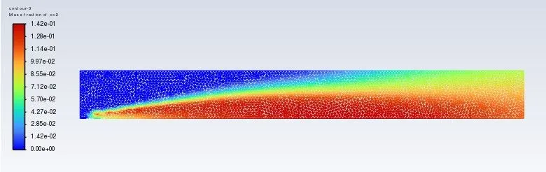
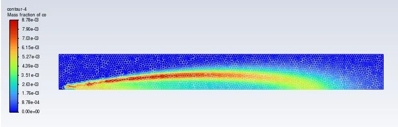
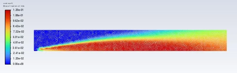
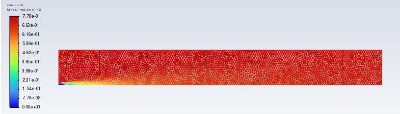
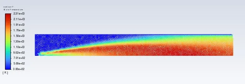
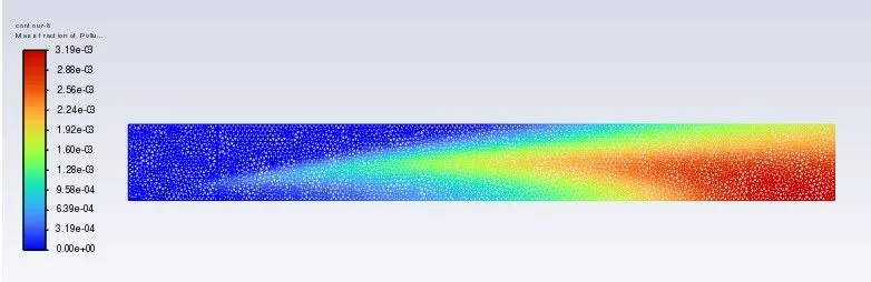
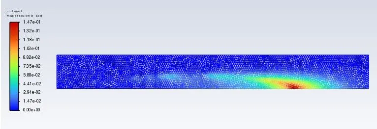
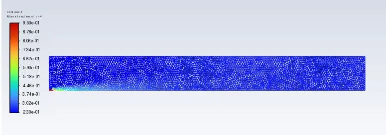
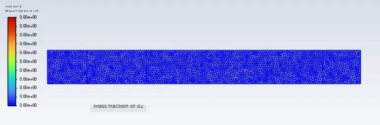
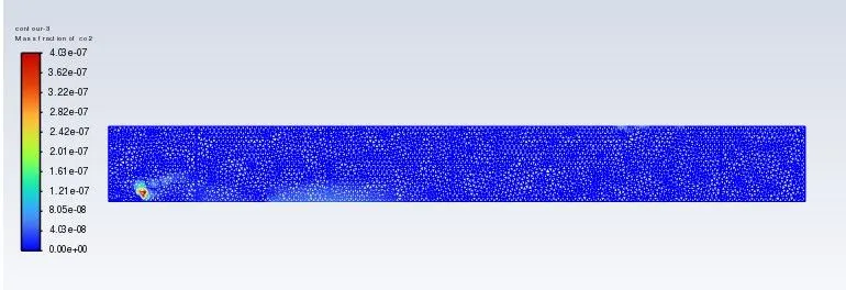
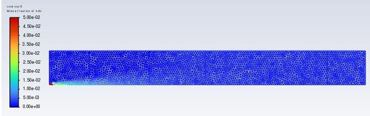
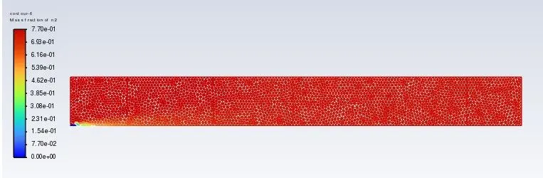
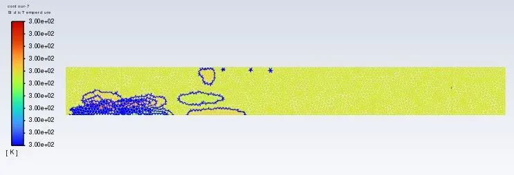
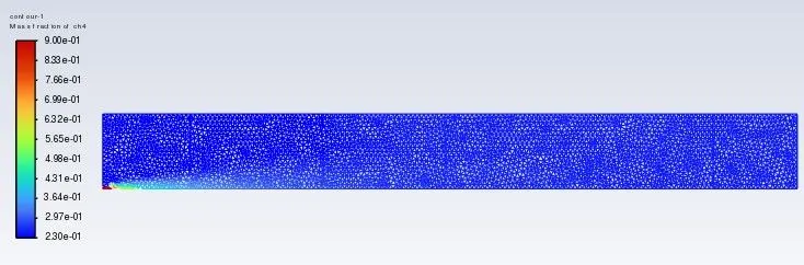
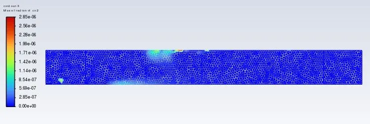
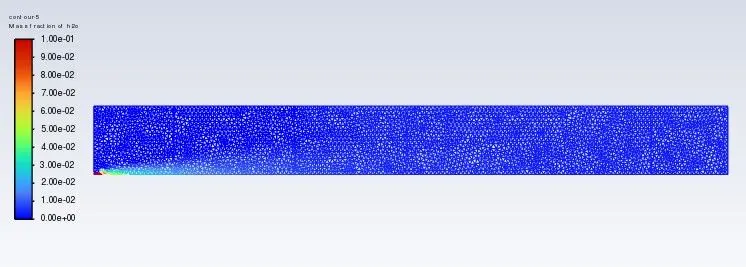
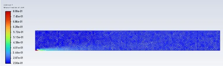
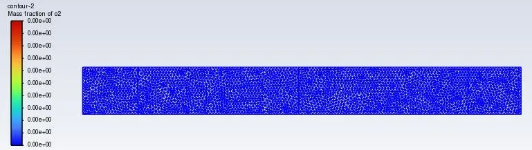
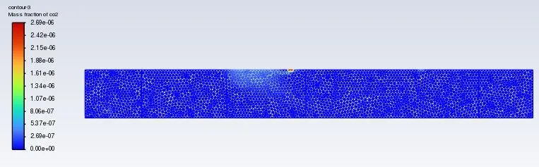
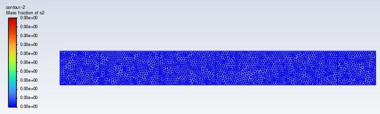
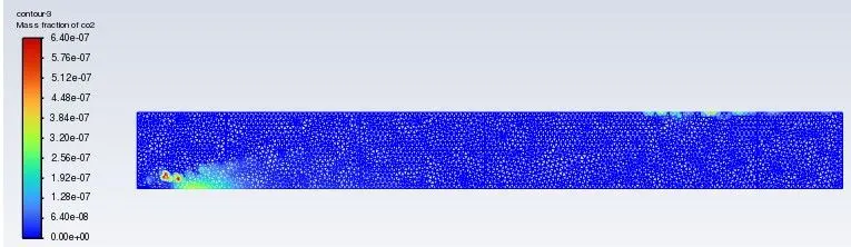
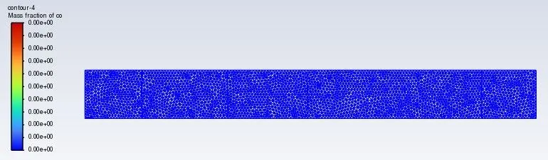
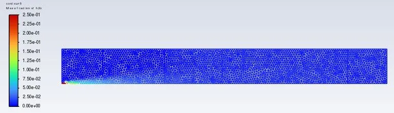
From the above results obtained from the simulation, it is observed that for first case (Case 1), the peak temperature is observed before the inlet also, the area where the mass fraction for CH4 species is highest. As the combustion happens, the mass fraction for that of CH4 decreases. For oxygen, mass fraction is high near the air inlet area, For species like CO2 and H2O, it is high in the region where temperature is high. For NOx and soot, mass fraction is greater at the exhaust (outlet) region.
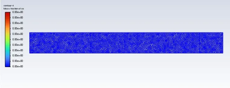
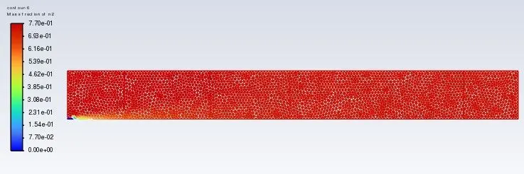
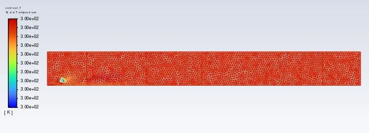
For case 2, as the water percentage is increased, the temperature decreases and hence, for CO species, increase in mass fraction can be observed while in the case of NOx and soot particles, mass fraction decreases. But, there is no significant change in that of mass fraction for species such as N2 and O2.
Therefore, it is evident that addition of water till an adequate percentage is beneficiary in reducing harmful pollutants such as NOx and soot particles rejected from the exhaust as a bi-product results of combustion.