Week 10 - Simulating Combustion of Natural Gas.
AIM:
PART 1:
To perform a combustion simulation on the combustor model and plot the variation of the mass fraction of the different species in the simulation.
PART 2:
Adding water content in the fuel and observe the effect of the results.
INTRODUCTION:
Combustion is a high-temperature exothermic redox chemical reaction between a fuel and an oxidant, usually atmospheric oxygen. When the fuel and air react, it releases heat and light energy. This heat and light energy results in the flame. Once the reaction takes place between the fuel and oxygen it will produce flames, heat and unburnt gases.
Uncatalyzed combustion in air requires relatively high temperatures. Complete combustion is stoichiometric concerning the fuel, where there is no remaining fuel, and ideally, no residual oxidant. Thermodynamically, the chemical equilibrium of combustion in air is overwhelmingly on the side of the products. However, complete combustion is almost impossible to achieve, since the chemical equilibrium is not necessarily reached, or may contain unburnt products such as carbon monoxide, hydrogen and even carbon (soot or ash). Thus, the produced smoke is usually toxic and contains unburned or partially oxidized products. Any combustion at high temperatures in atmospheric air, which is 78 percent nitrogen, will also create small amounts of several nitrogen oxides, commonly referred to as NOx, since the combustion of nitrogen is thermodynamically favoured at high, but not low temperatures. Since burning is rarely clean, fuel gas cleaning or catalytic converters may be required by law.
TYPES OF COMBUSTION SIMULATION IN ANSYS FLUENT:
BASED ON MIXING:
- Non-premixed combustion.
- Pre-mixed combustion.
- Partially premixed combustion.
BASED ON PHASE:
- Fluid phase (volumetric reactions)
- Wall (surface reactions)
- Particles (surface reactions)
- Porous regions (after-treatment system)
BASED ON MIXING:
NON-PREMIXED COMBUSTION:
This type of combustion occurs when oxidizer and fuel mixture enters the reaction zone in distinct streams or not initially mixed. Ex., diesel engines.
PRE – MIXED COMBUSTION:
The fuel and oxidizer are mixed at molecular level before the combustion. Ex., carburetor.
PARTIALLY PRE-MIXED COMBUSTION:
It is in between non-premixed and pre-mixed combustion where the fuel and oxidizer are partially pre-mixed at non-uniform ratios before combustion.
BASED ON PHASE:
FLUID PHASE:
The volumetric reaction takes place in fluid region.
WALL:
Combustion takes place on a wall or surface. Ex: evaporation.
PARTICLE:
Combustion takes place on the surface of the particles. Ex:coal combustion.
POROUS REGIONS:
Combustion takes place inside the pores. These reactions take place above the high – pressure drop region.
COMBUSTION SOURCE CALCULATION:
FINITE RATE CHEMISTRY:
This model derives ODE for all species and solves them. It results in accurate solutions but the computational time required to solve the ODE is increased as the number of species involves is more.
MIXING BASED MODEL:
EDDY DISSIPATION MODEL:
In this model, the combustion takes place when there is a presence of turbulence, hence it does not require any heat source to initiate the combustion reaction. This model is valid for non-premixed fuel mixture.
FINITE RATE EDDY DISSIPATION MODEL:
It is the combination of both finite rate chemistry and the eddy dissipation model. In this model, the kinetic rate is calculated in addition to the reaction rate calculated from the eddy dissipation model.
Then the slowest reaction is chosen,
- If turbulence is low, the species mixing rate is low, this limits the reaction rate.
- If turbulence is high, the kinetic rate is low, this limits the reaction rate.
SIMULATION PROCEDURE:
GEOMETRY:
- The model is imported into spececlaim.
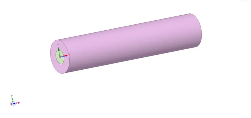
- Then the parts are combined using combine tool in Ansys fluent.
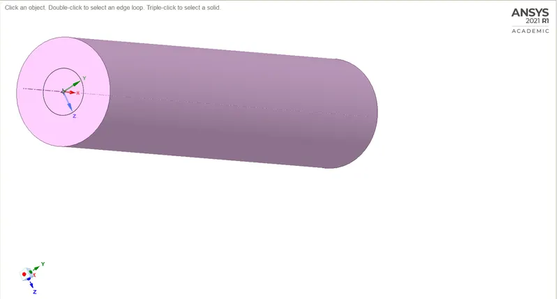
- The plane is created along the three axis and splitting the body of the 3D model.
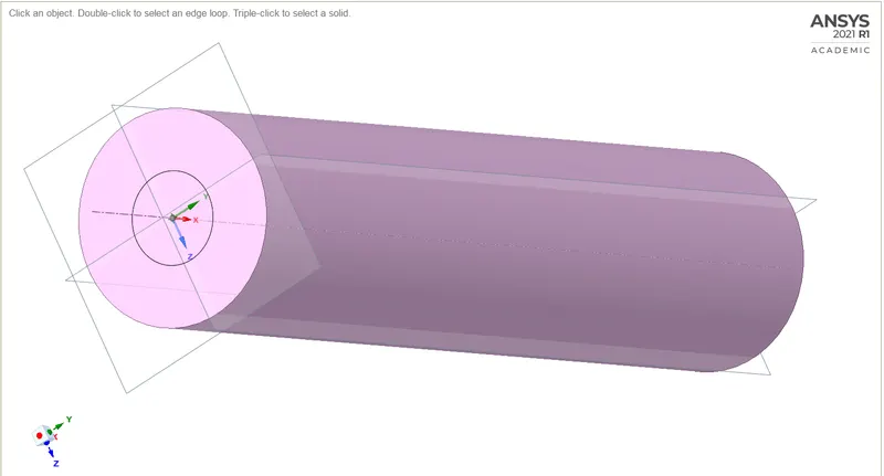
- Then the body is splitted into half along the z axis.
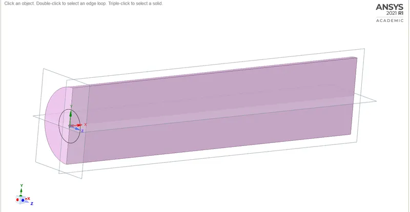
- Then the body is again splitted into half using the split body tool along y axis.
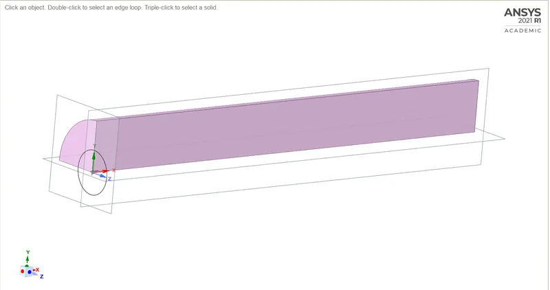
- Then the face of the model is copied and pasted into the new workspace in space claim.
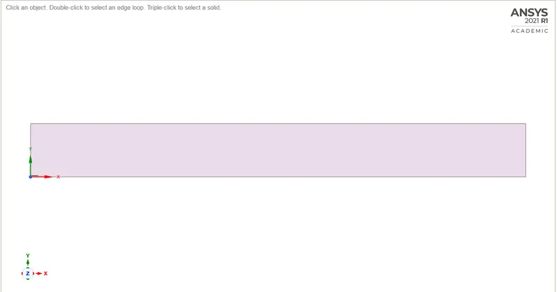
MESHING:
- The named selections are made for the model.
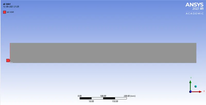
INLET:
AIR:
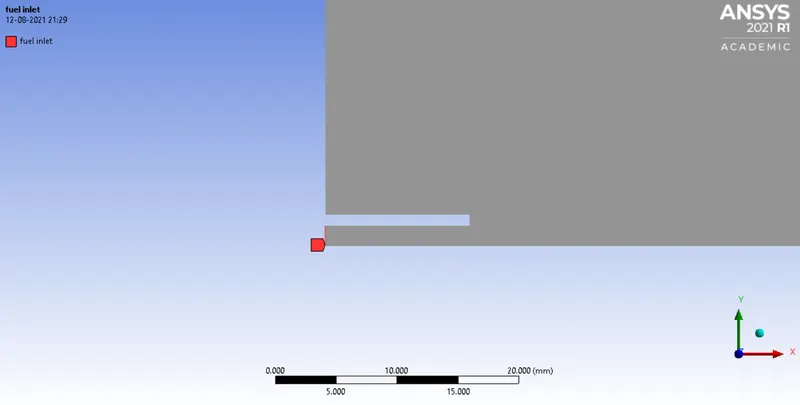
FUEL:
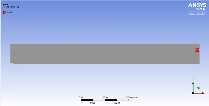
OUTLET:
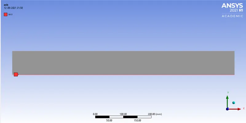
AXIS:
- The model is discretized into small elements of size 1mm and capture proximity is turned on and number of cells across gap as 3.
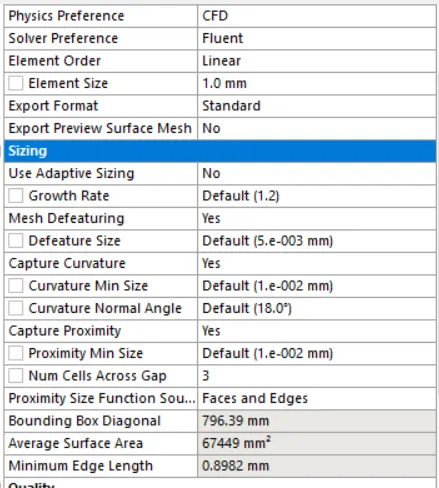
- Number of nodes – 68325
- Number of elements – 67421

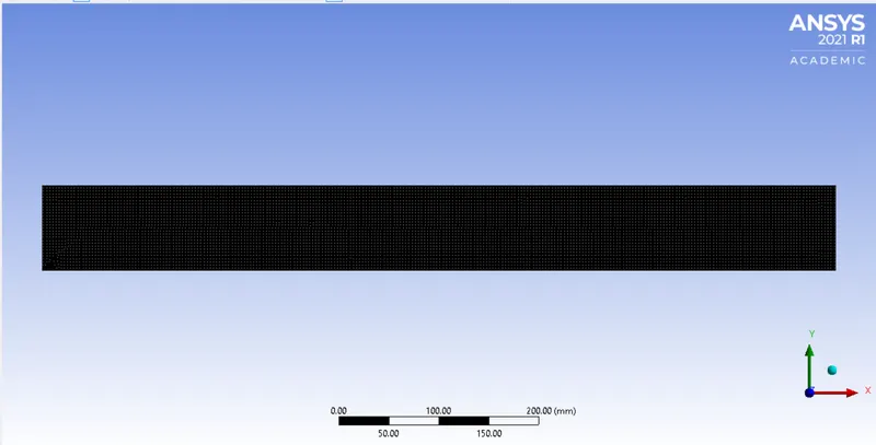
- The final meshed model will looks like the image below
SETUP:
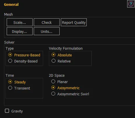
GENERAL:
- Type – pressure based
- Velocity formulation – absolute
- Time – steady
- 2D space - axisymmetric
MODEL:
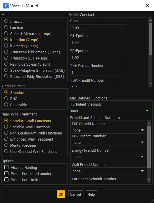
- Energy – on
- Viscous – standard k-epsilon with standard wall functions.
SPECIES MODEL:
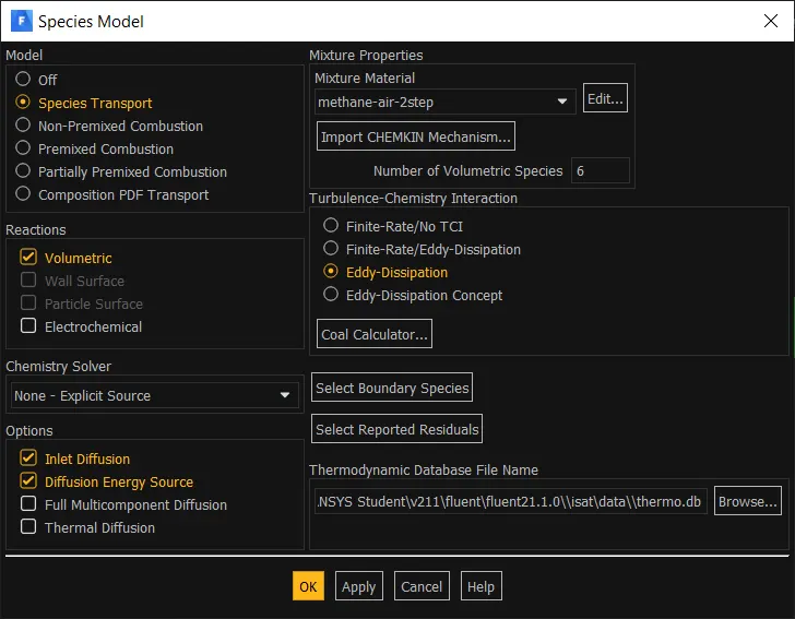
- Model – species transport
- Reactions – volumetric
- Options – inlet diffusion, diffusion energy source.
- Mixture material – methane air 2 step
- Turbulence chemistry interaction – eddy dissipation.
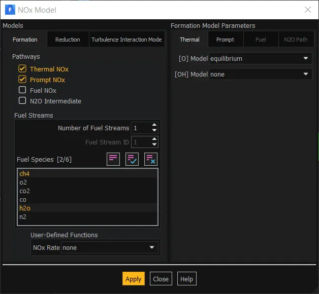
NOX MODEL:
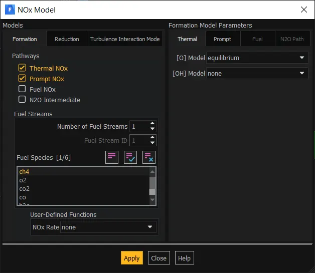
- Pathways – thermal, prompt NOx
- Fuel species – CH4
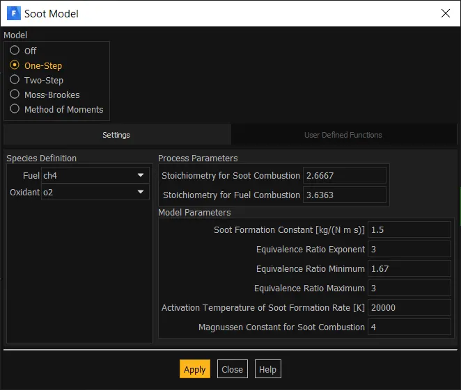
SOOT MODEL:
- Model – one step
- Fuel – CH4
- Oxidant – O2
MATERIAL:
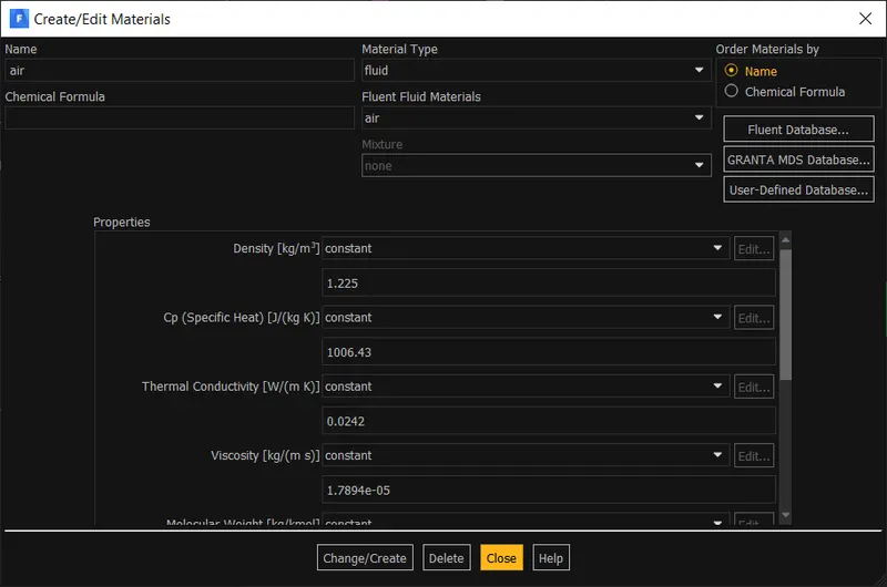
FLUID MATERIAL:
- Fluid - air
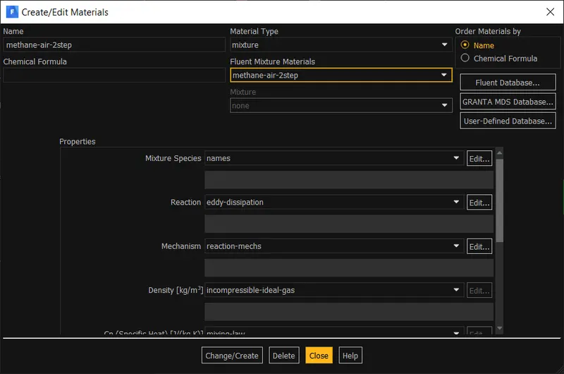
MIXTURE MATERIAL:
- Mixture – methane-air-2step
CELL ZONE:
BOUNDARY CONDITION:
INLET:
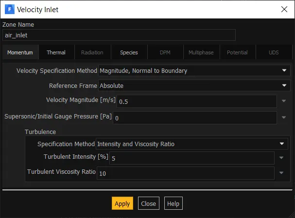
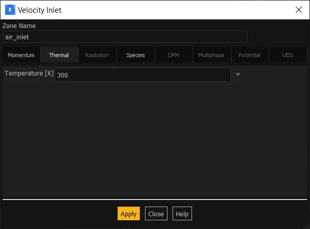
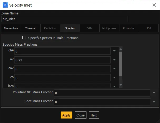
AIR INLET:
- Velocity – 0.5m/s
- Temperature – 300k
- O2 – 0.23
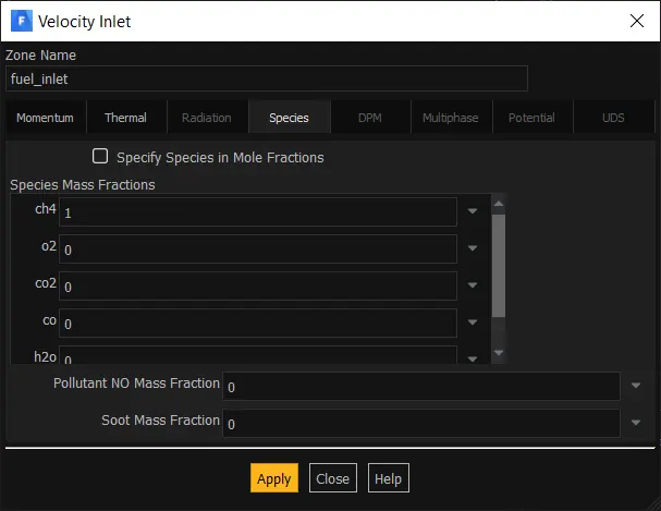
FUEL INLET:
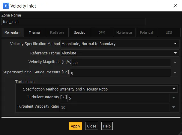
- Velocity – 80m/s
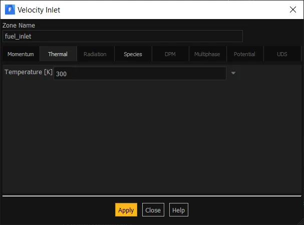
- Temperature – 300k
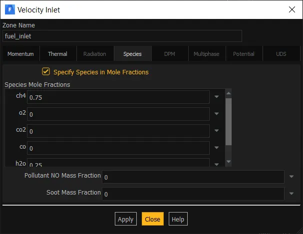
- CH4 - 1
AXIS:
WALL:
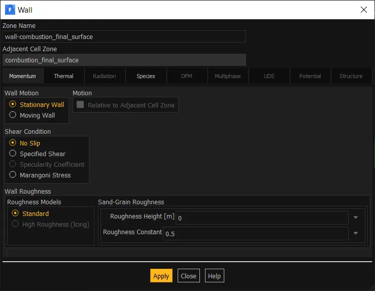
- Wall – Noslip stationary wall with standard wall roughness.
INTERIOR:
OUTLET:
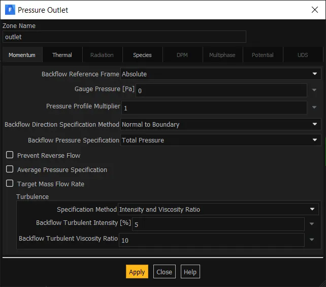
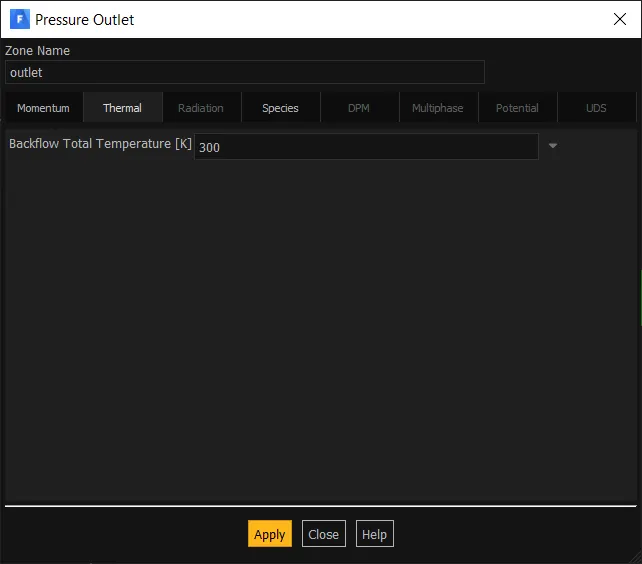
- Pressure outlet – zero gauge pressure.
INITIALIZATION:
Hybrid initialization.

RESULTS:
PART-1:
RESIDUAL:
TEMPERATURE CONTOUR:
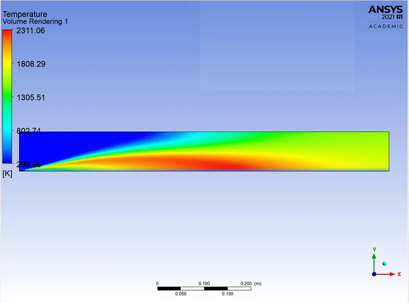
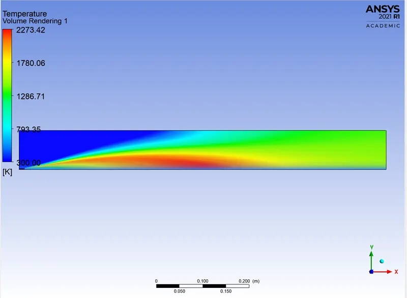
From the temperature contour we can say that temperature is higher at the regions where the air fuel mixture takes place.
PROBE LOCATION:
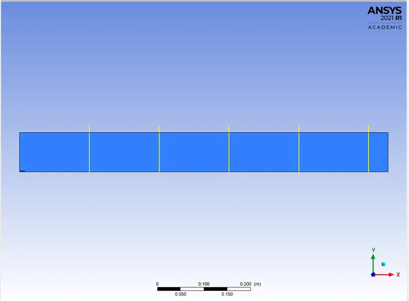
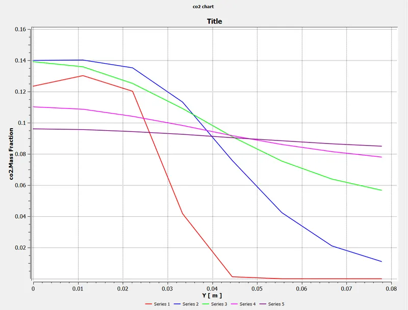
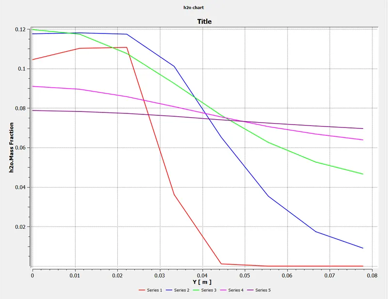
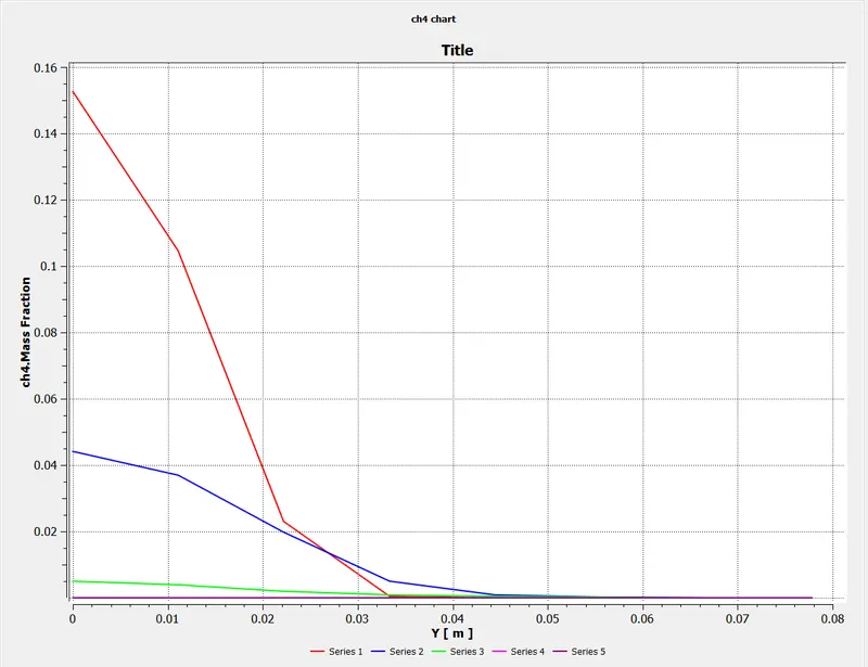
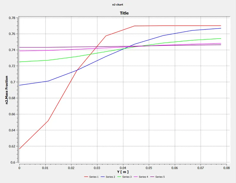
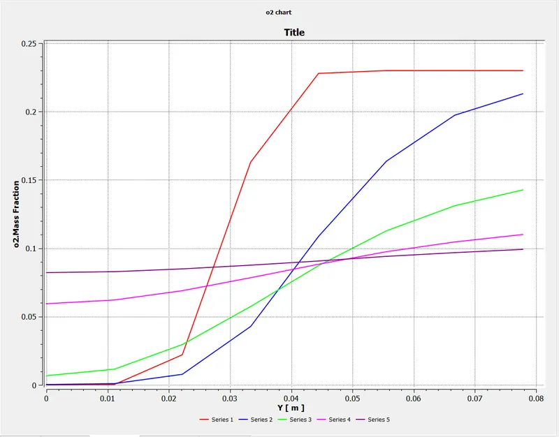
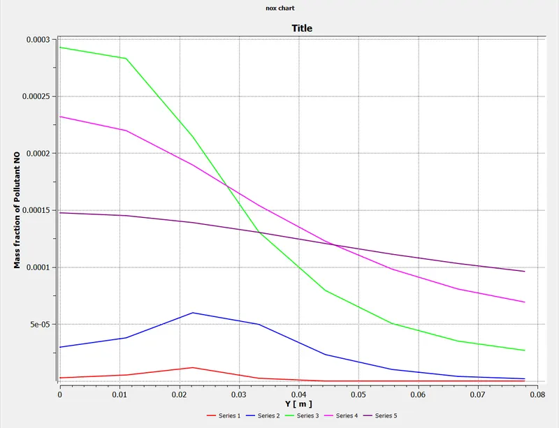
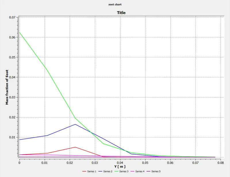
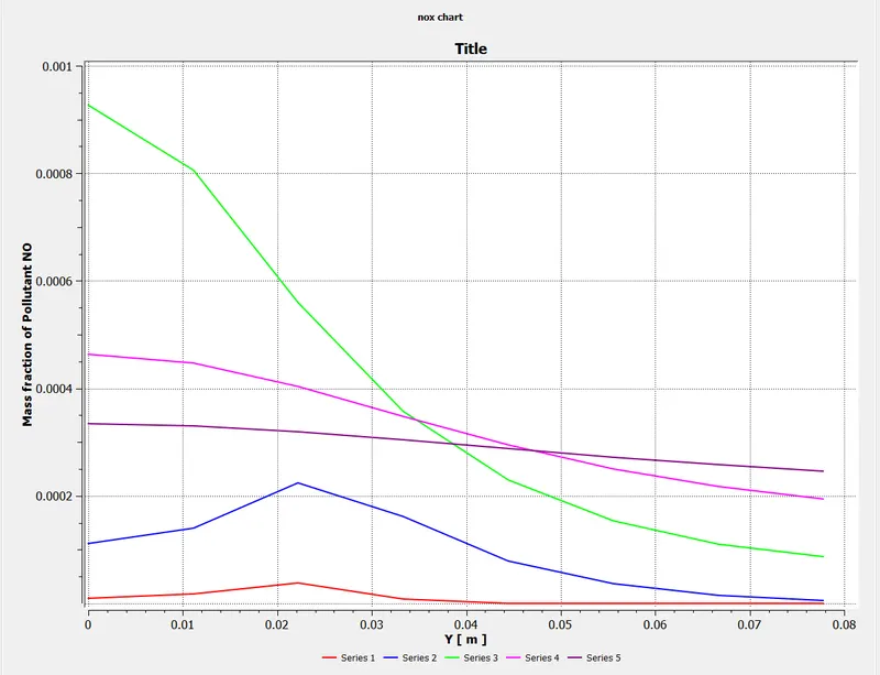
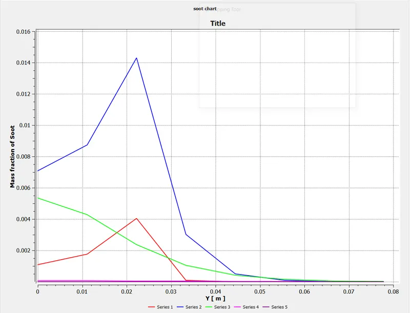
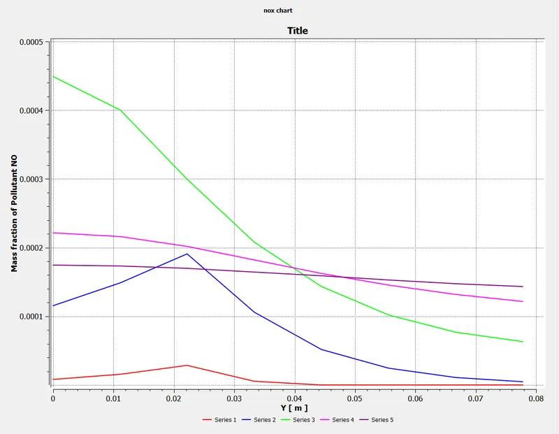
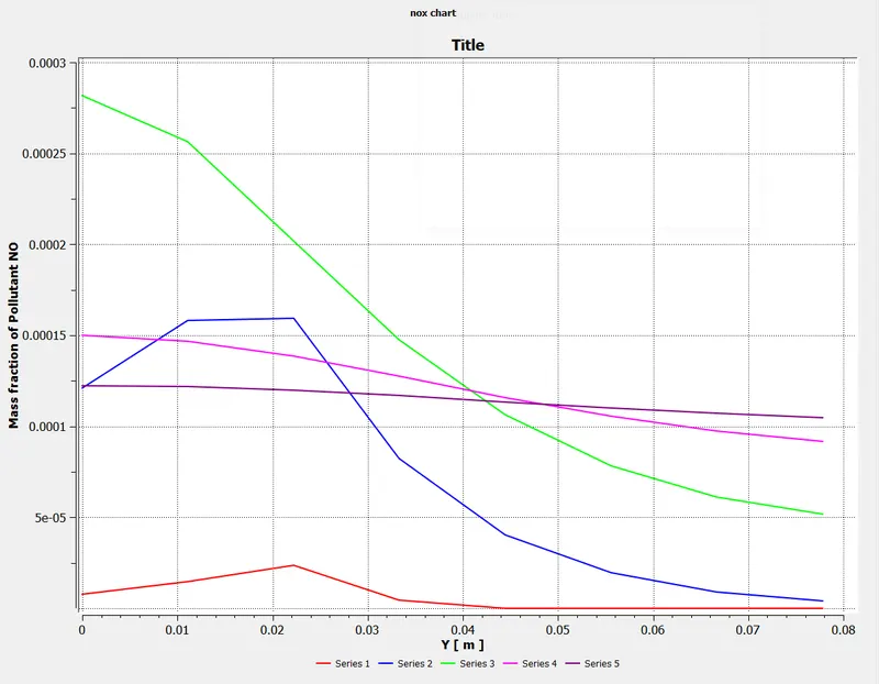
we are considering five line probes at distance of 0.15,0.30, 0.45, 0.60 and 0.75m respectively.
CO2:
MASS FRACTION:
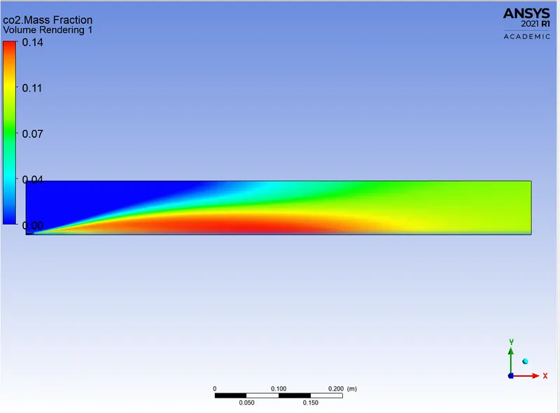
From this contour we can say that CO2 mass fraction is higher at the regions where temperature is higher.
CHART:
H2O:
MASS FRACTION:
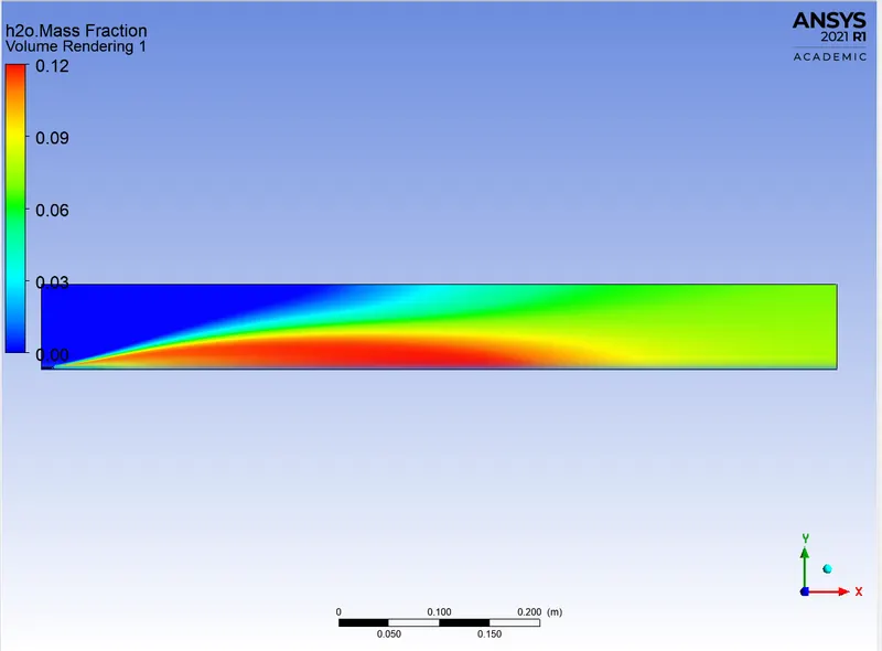
From this contour we can say that H2O mass fraction is higher at the regions where CO2 mass fraction is higher.
CHART:
CH4:
MASS FRACTION:
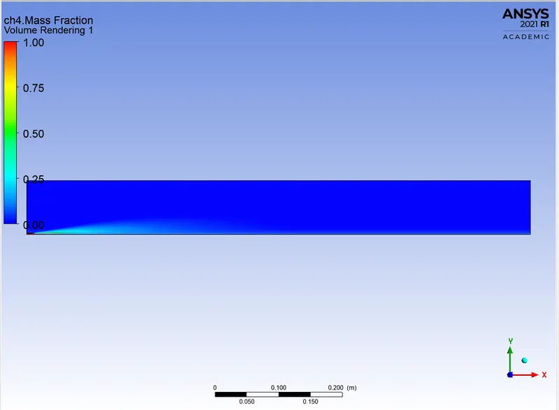
From this contour, we can say that CH4 mass fraction is higher near the fuel inlet where the fuel is being injected and decreases once the combustion takes place.
CHART:
N2:
MASS FRACTION:
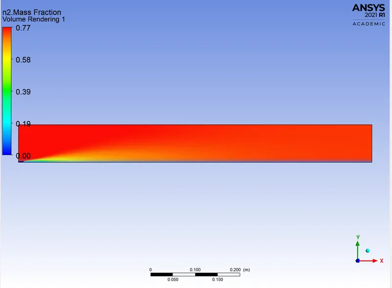
From this contour, we can say that N2 mass fraction is uniformly distributed across the combustor.
CHART:
O2:
MASS FRACTION:
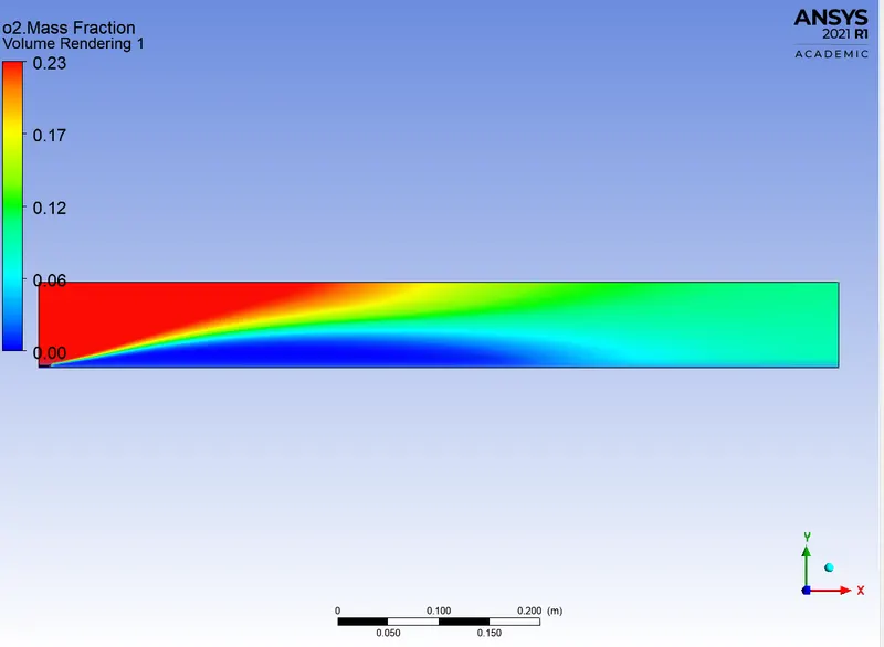
From this contour we can say that O2 mass fraction is higher near the air inlet where the air is being injected.
CHART:
NOx:
MASS FRACTION:
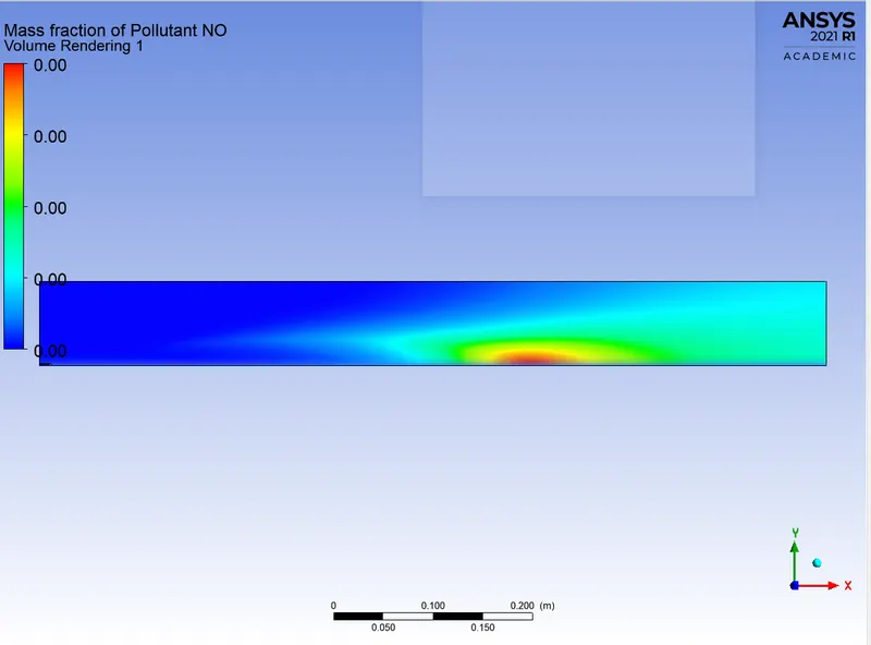
From this contour, we can conclude that mass fraction of NO is higher at the outlet of the combustor. [As i used precision as 2 and fixed it is showing values as zero in contour].
CHART:
SOOT:
MASS FRACTION:
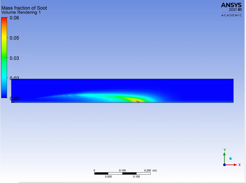
From this contour we can conclude that soot mass fraction is higher at the outlet.
CHART:
PART-2:
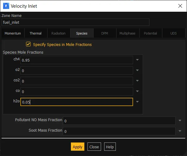
WATER 5%
FUEL INLET BOUNDARY:
NOx MODEL:
RESULTS:
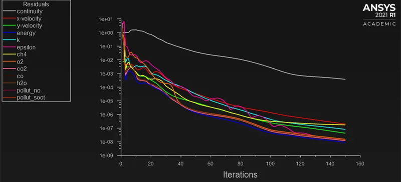
RESIDUAL:
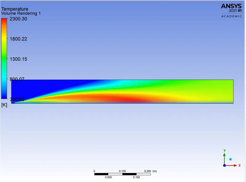
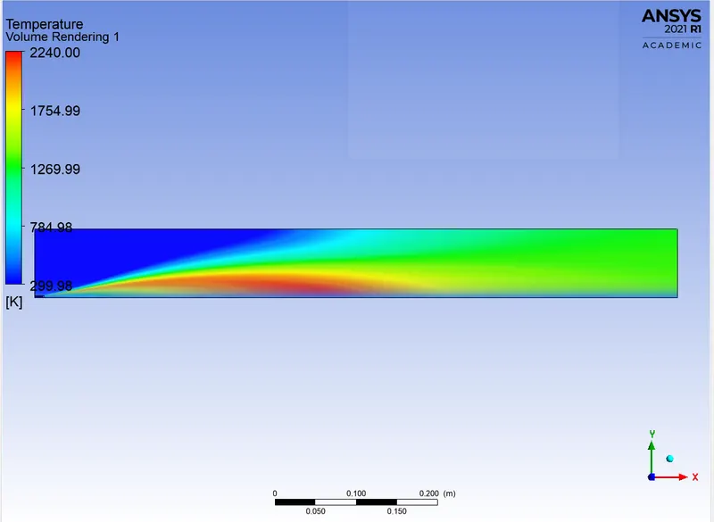
TEMPERATURE CONTOUR:
NOx:
MASS FRACTION:
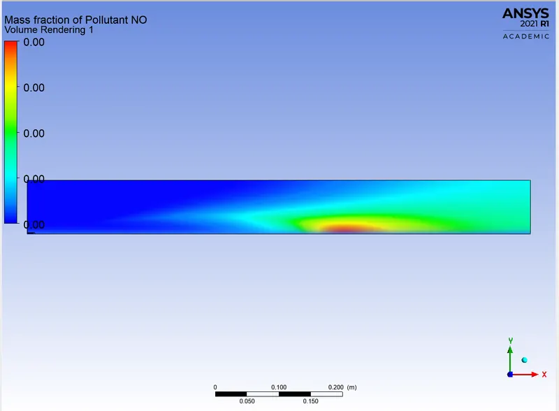
CHART:
SOOT:
MASS FRACTION:
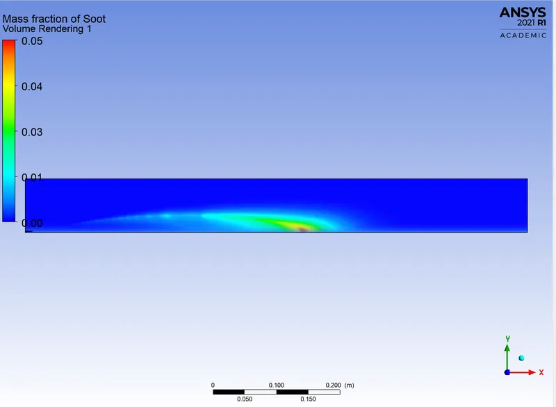
CHART:
WATER 15%
FUEL INLET BOUNDARY:
RESULTS:
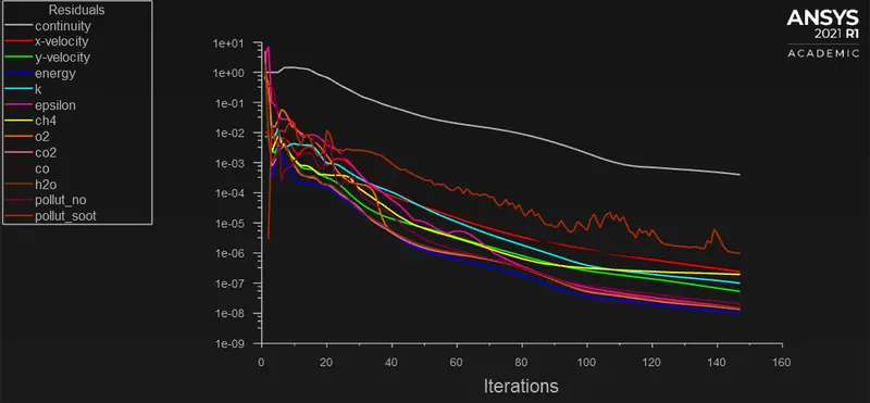
RESIDUAL:
TEMPERATURE CONTOUR:
NOx:
MASS FRACTION:
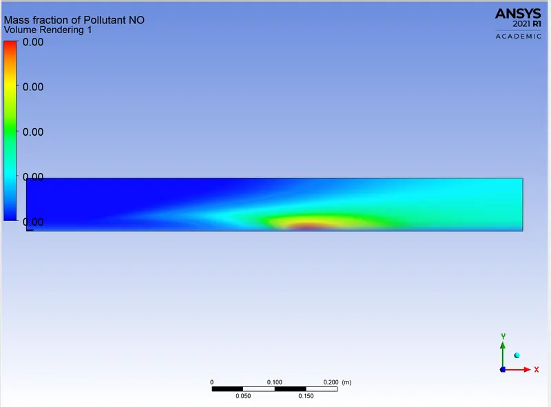
CHART:
SOOT:
MASS FRACTION:
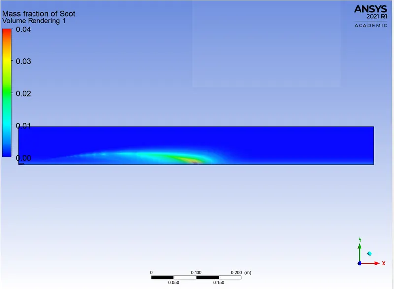
CHART:
WATER 25%
FUEL INLET BOUNDARY:
RESULTS:
RESIDUAL:
TEMPERATURE CONTOUR:
NOx:
MASS FRACTION:
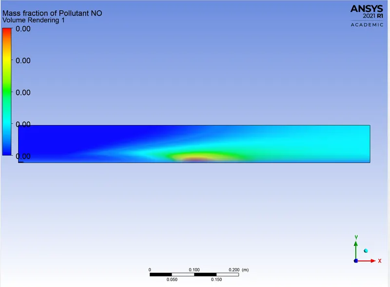
CHART:
SOOT:
MASS FRACTION:
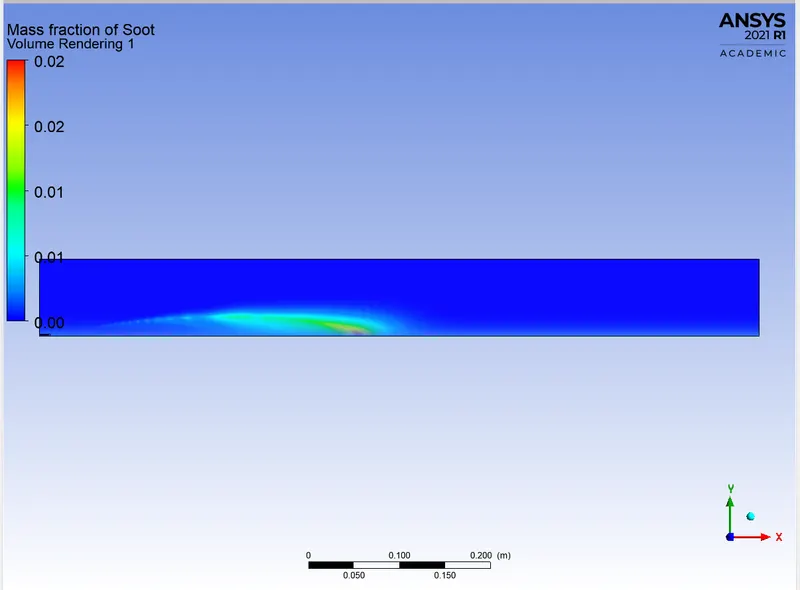
CHART:
WATER 30%
FUEL INLET BOUNDARY:
RESULTS:
RESIDUAL:
TEMPERATURE CONTOUR:
NOx:
MASS FRACTION:
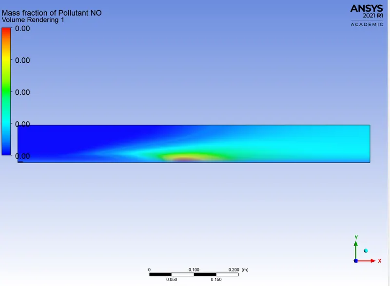
CHART:
SOOT:
MASS FRACTION:
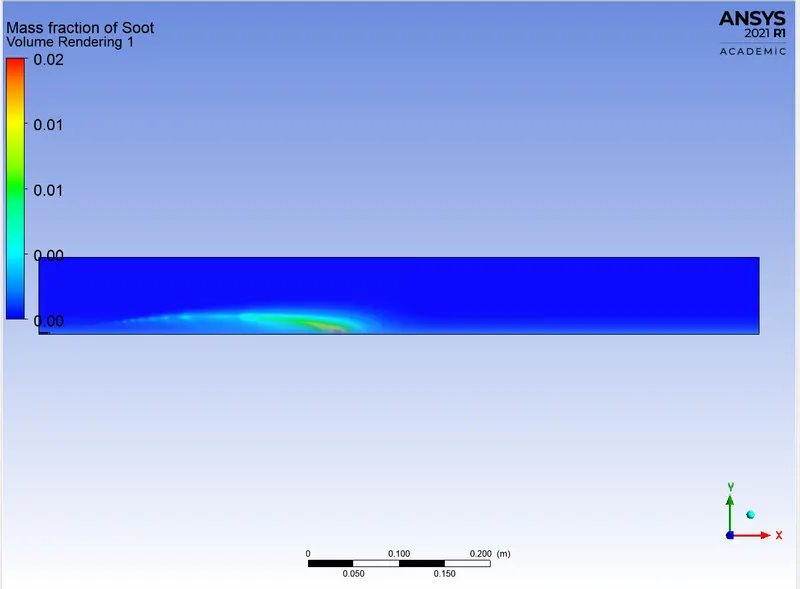
CHART:

OBSERVATION FROM PART-2:
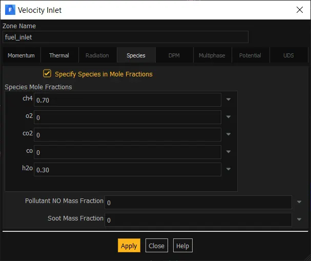
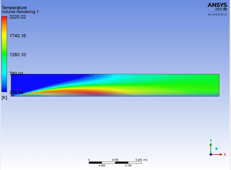
- The temperature drops as we add water to the fuel from 5 to 30%.
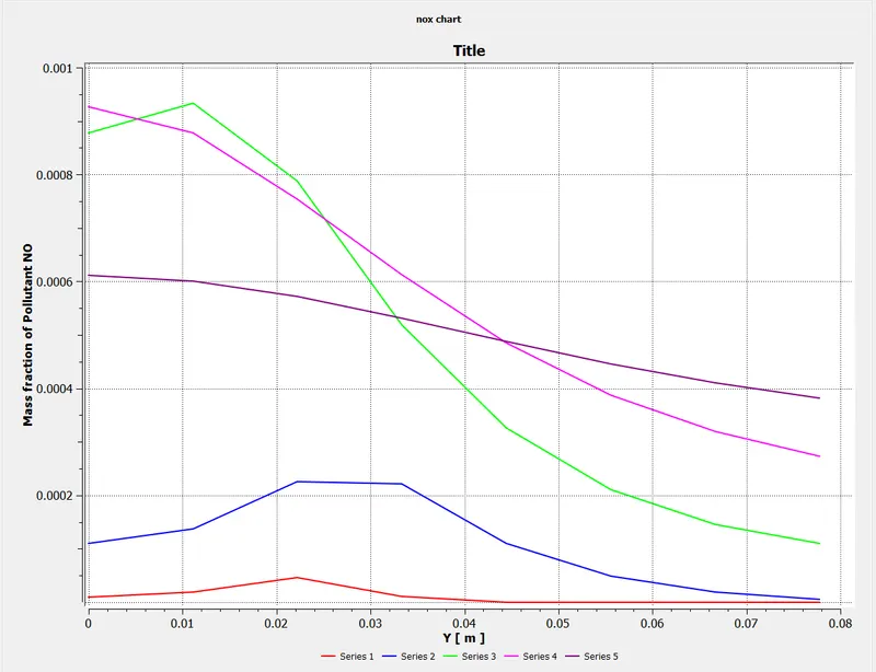
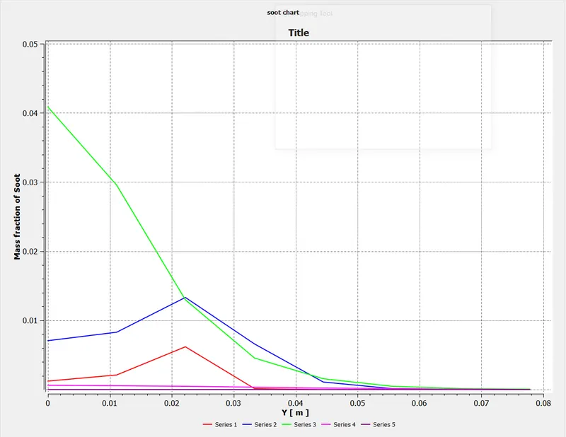
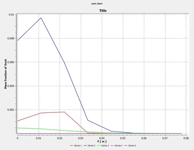
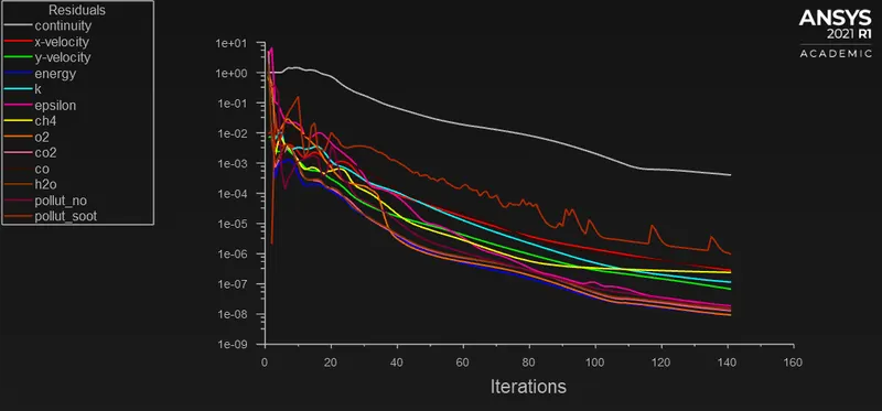
- The mass fraction of NO and soot decreases as we add water to the fuel by 5 to 30%.
CONCLUSION:
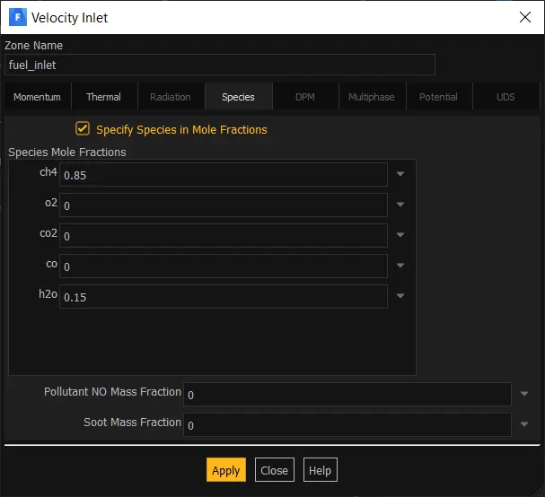
In this project the mass fraction of pollutants from NOx and soot emissions are predicted using Ansys Fluent. The results obtained from the simulation shows that addition of water into the fuel decreases the temperature of combustor and also helps in reducing the mass fraction of NOx and soot.