Week 10 - Simulating Combustion of Natural Gas.
Simulating Combustion of Natural Gas
Aim: To perform combustion simulation of natural gas.
Objective:
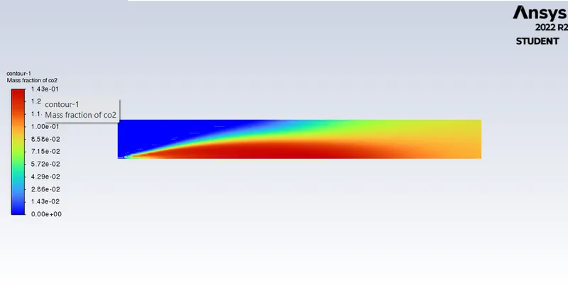
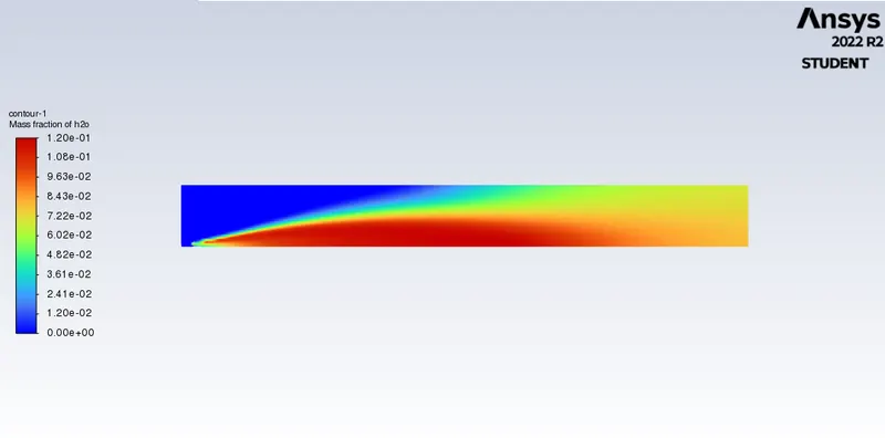
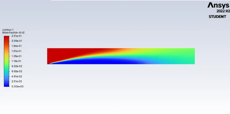
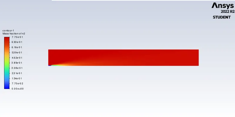
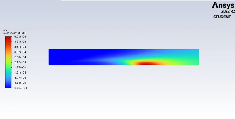
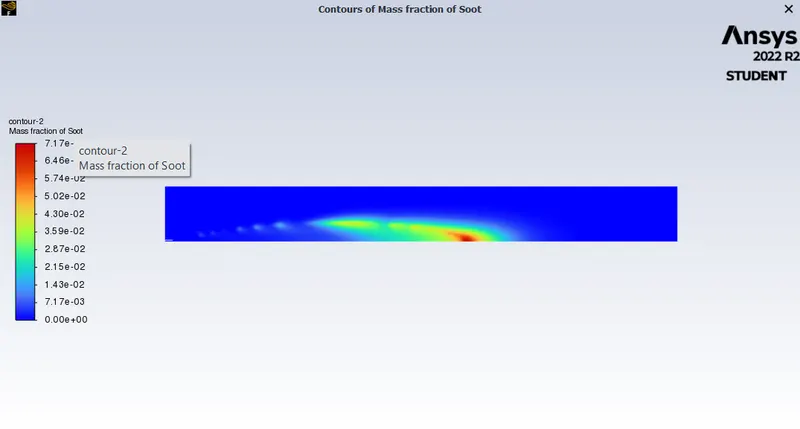
1. Perform a combustion simulation on the combustor model and plot the variation of the mass fraction of the different species’ in the simulation using line probes at different locations of the combustor as shown in Fig. You need to plot for CO2, H2O, CH4, N2, O2, NOx emissions & Soot formation
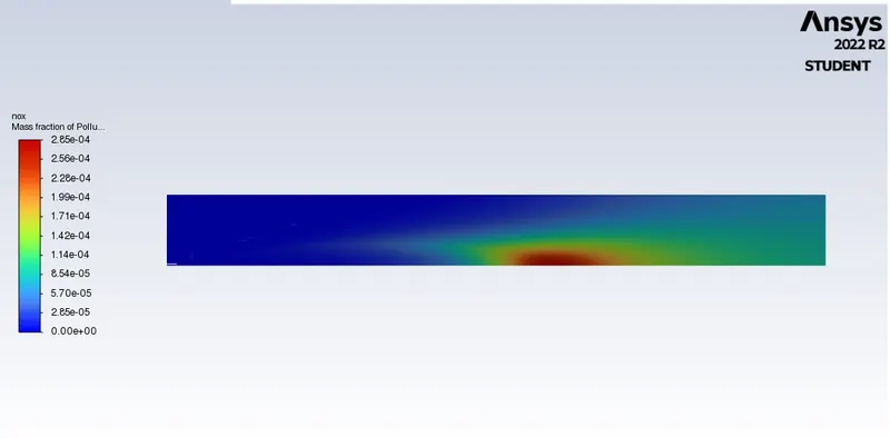
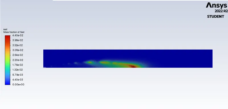
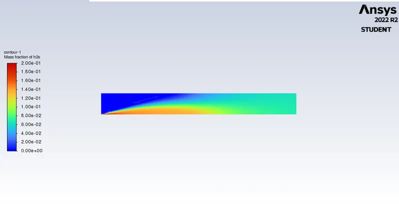
2. To add the water content in the fuel from 5% to 30% by mole and observe the effect of it on the results. It is necessary to provide line plots and contours to prove your claim.
Theory:
Combustion is defined as a chemical reaction in which a hydrocarbon reacts with an oxygen to form products, accompanied by the release of huge energy in the form of heat.
The simulation of combustion can be divided into two types-
1. Combustion based on Mixing
Non-Premixed Combustion:
Fuel and oxidizer enter the reaction zone in distinct streams.
It occours during direct injection or late injection of fuel in IC engines.
Premixed Combustion:
In premixed combustion,fuel and oxidizer are mixed at the molecular level prior to ignition.
Combustion occurs as flames front propagating into the unburnt reactants.
Partially Premixed Combustion:
Partially premixed combustion systems are premixed flames with non-uniform fuel-oxidizer mixtures(equivalence ratios).
Such falmes include premixed jets discharging into an inert atmosphere, lean premixed combustors with difussion pilot fames and cooling air jets, and imperfectly mixed inlets.
2. Combustion based on Phase
Fluid Phase (Volumetric Reactions):
Combustion takes place in the fluid region.
Wall (Surface Reactions):
Combustion takes place on the wall or a solid surface.
Particles ( Surface Reactions):
Combustion takes place on the Lagrangian particles.
Porous Region :
Combustion takes place in a porous region the reactions in an after-treatment system
The general reaction of combustion is given as follows-
CH4+ar(O2+3.76N2)→aCO2+bH2O+cN2CH4+ar(O2+3.76N2)→aCO2+bH2O+cN2
Procedure:
Geometry:
Merge the bodies except the inlet.
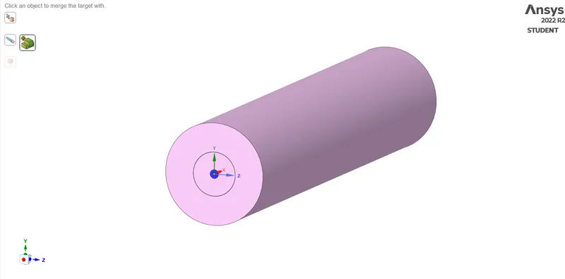
Create the planes and split the bodies.
Copy the plane, extracting the fluid plane.
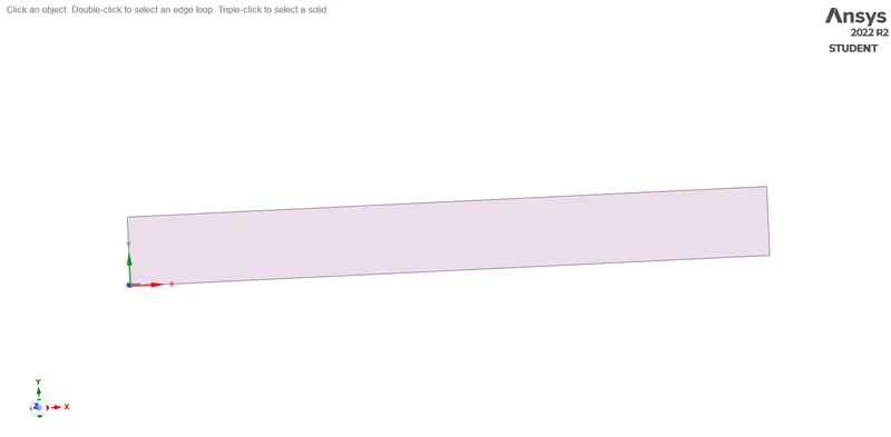
Meshing:
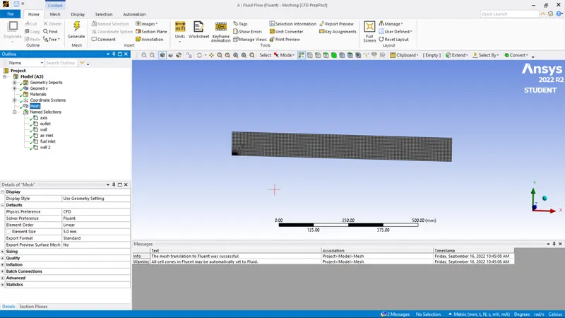
Mesh with length = 5 mm.
Assign the name accordingly for all edges.
Curvature - Yes
Setup:
Part 1:
Solver
Steady state
Axisymmetric.
Model:
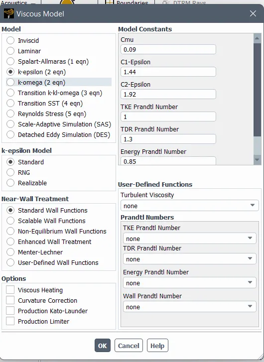
Species
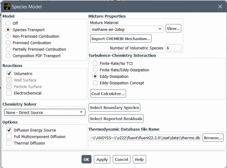
Air inlet = 0.5 m/s , 300K, O2 = 0.23
Fuel inlet = 80 m/s, 300K, CH4=1
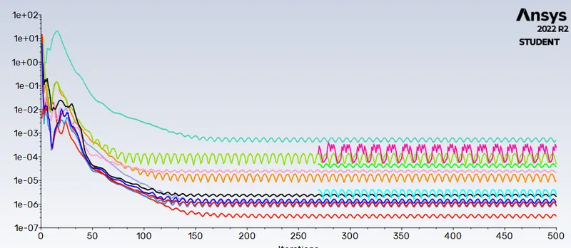
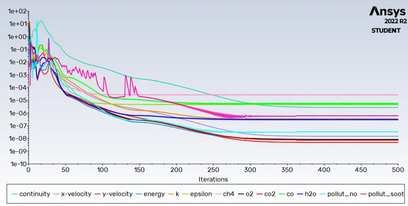
Scaled residuals:
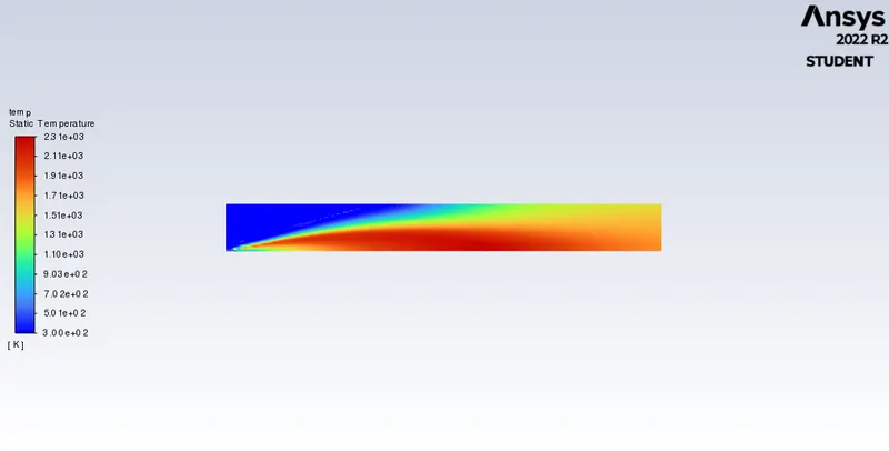
Temperature contour:
Results:
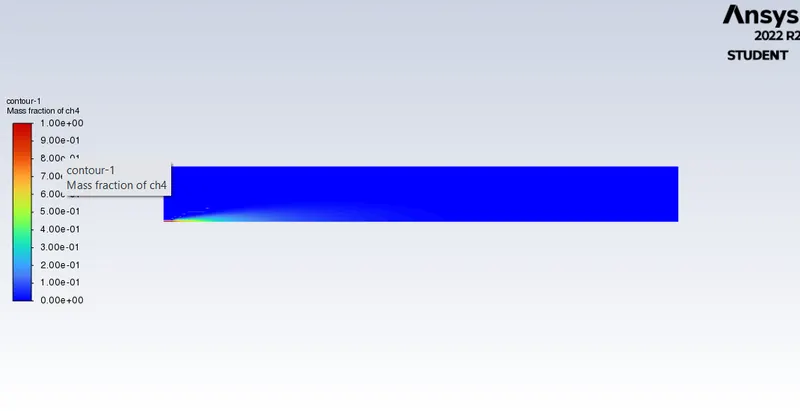
CH4 plot
CO2 :
H2O:
O2
N2:
NOx emission:
Soot formation:
Part 2:
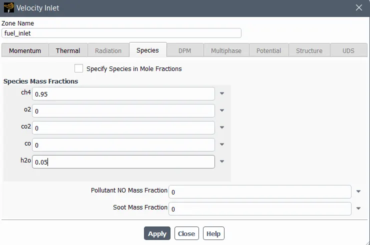
Adding water content in fuel
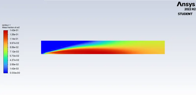
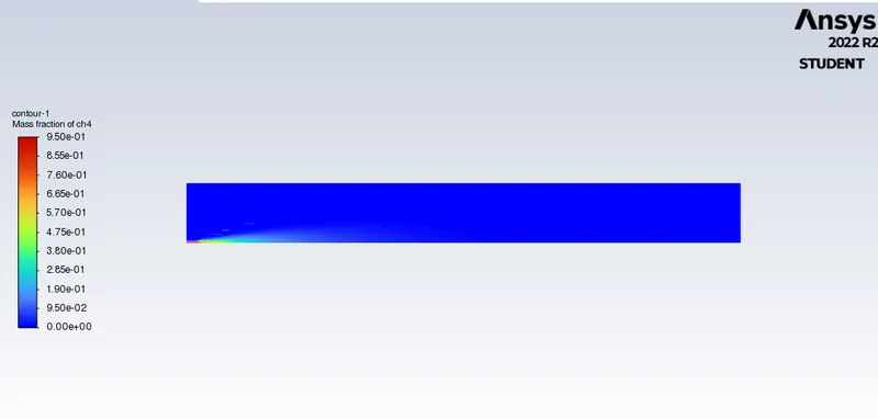
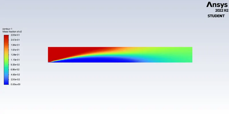
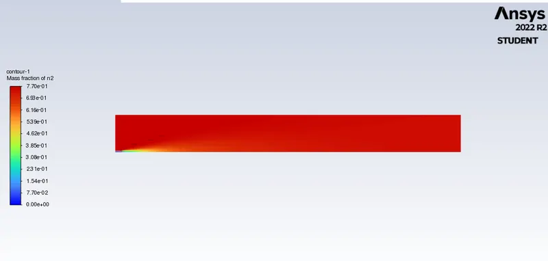
Case 1: 5 % H20 and 95% fuel
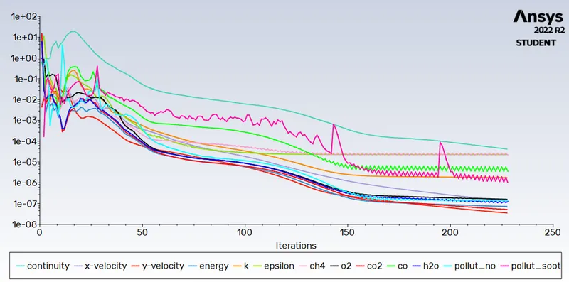
Scaled residuals:
Mass fraction CO2:
Mass fraction CH4:
Mass fraction O2:
Mass fraction N2:
Mass fraction H2O:
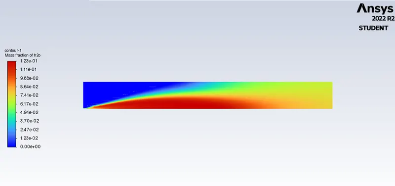
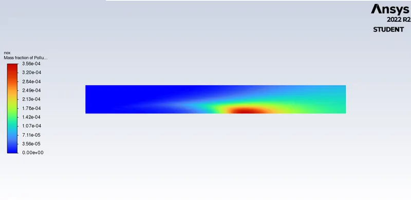
NOx formation :
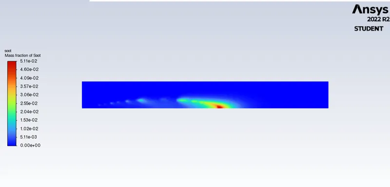
Soot formation:
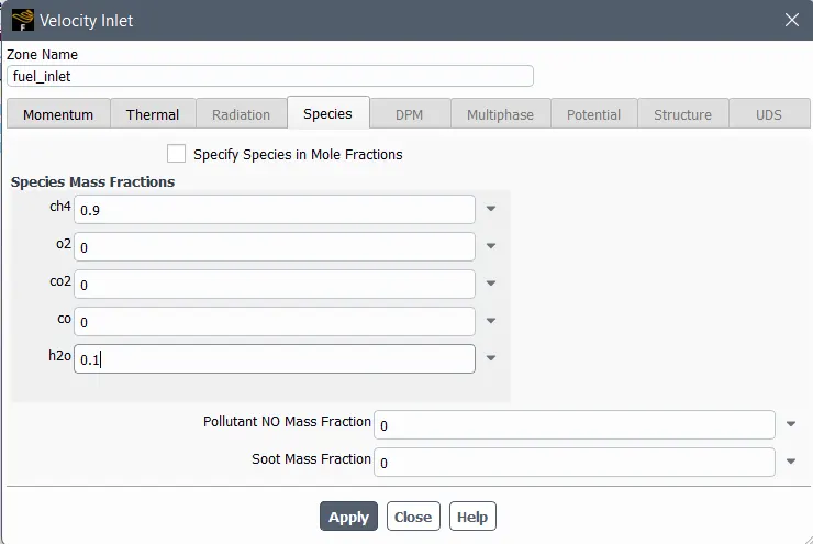
Fuel inlet:
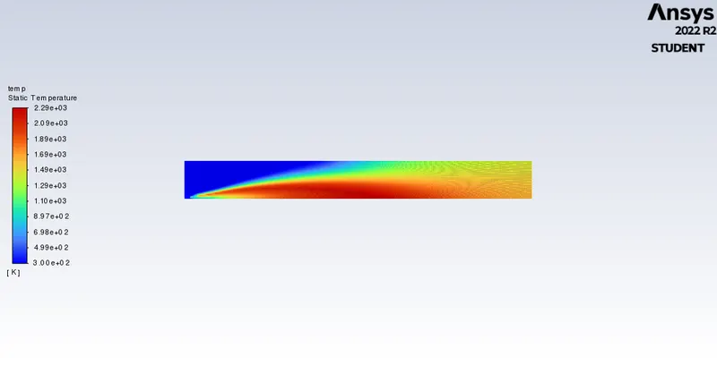
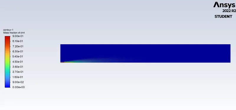
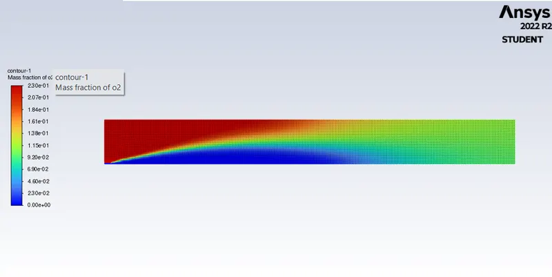
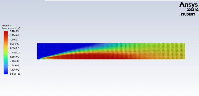
CH4 - 90% H20 - 10%.
Temperature contour:
Mass fraction CH4:
Mass fraction O2:
Mass fraction CO2:
Mass fraction N2:
Mass fraction NOx:
Soot formation:
CH4 - 80 % H20 - 20%
Residuals:
Temperature contour:

Mass fraction H2O:
Mass fraction O2:
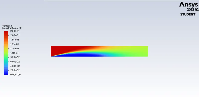
Mass fraction CH4:
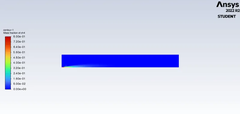
Mass fraction N2:
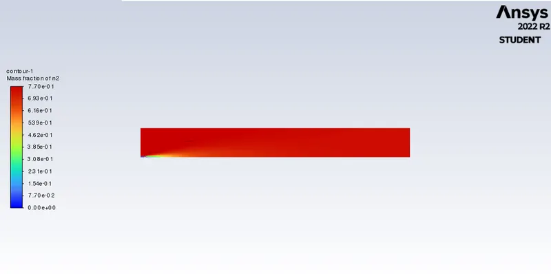
NOx :
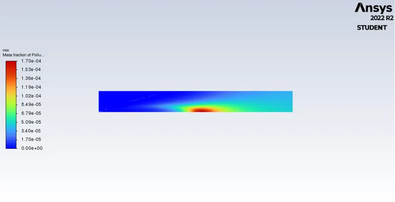
Soot formation:
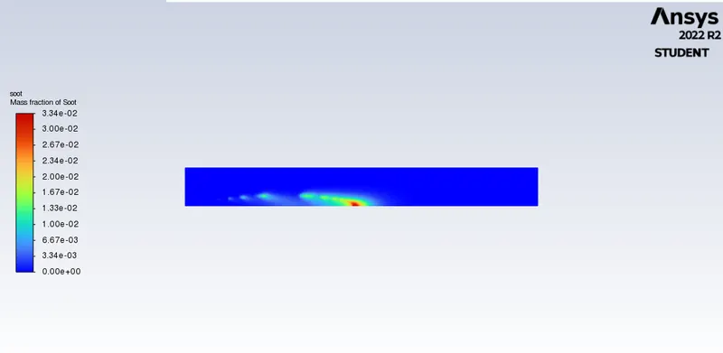
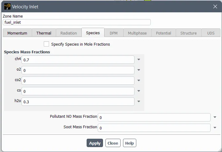
CH4 - 70 % H20 - 30%
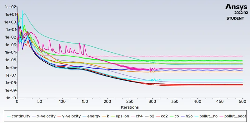
Sclaed residuals:
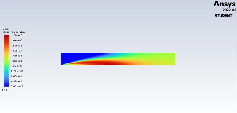
Temperature cotour:
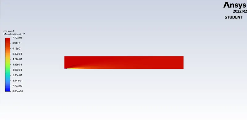
Mass fraction N2:
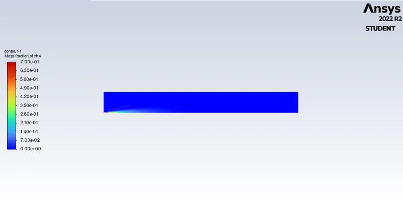
Mass fraction CH4:
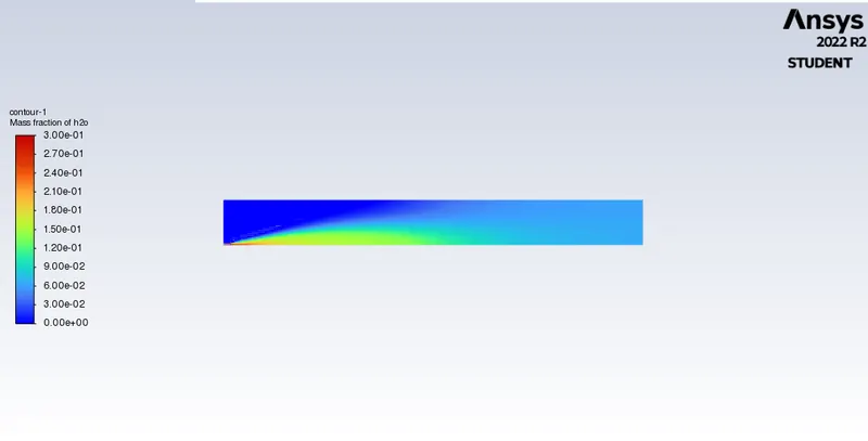
Mass fraction H2O:
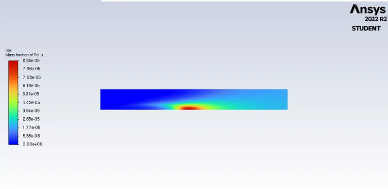
NOx contour:
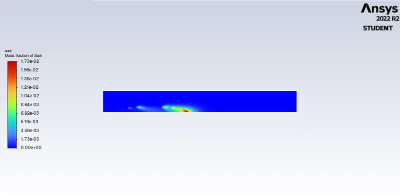
SOOT formation:
Conclusion:
Due to this incomplete combustion of fuel, SOOT formation takes place.
There is very small decrease in temperature as we add water in fuel in each case from 5 % to 30% and amount of decrease in SOOT formation along.
The simulation provides a complete temperature distribution along the geometry and contours of various species.
Adding water to fuel indeed reduce the formation of harmful pollutants such as NOx and soot.