Week 10 - Simulating Combustion of Natural Gas.
OBJECTIVE:
We are to simulate Methane Combustion on a combustor model and derive the following two results:
- The variation of the mass fraction of the different species in the simulation using line probes at other locations of the combustor
- Add the water content in the fuel from 5% to 30% by mole and observe its effect of it on the results
INTRODUCTION AND THEORY:
COMBUSTOR:
A combustor is a component or area of a gas turbine, ramjet, or scramjet engine where combustion occurs. It is also known as a burner, combustion chamber or flame holder. The compression system in a gas turbine engine supplies high-pressure air to the combustor or combustion chamber. As the fuel/air mixture burns, the combustor then warms this air at a steady pressure. The fuel/air mixture warms up and rapidly expands as it burns. The burned mixture is exhausted from the combustor through the nozzle guiding vanes and into the turbine. The exhaust is directly sent out through the nozzle in the case of ramjet or scramjet engines.
A combustor must contain and maintain stable combustion despite very high air flow rates. Combustors are specifically made to combine and ignite the fuel and air before adding more air to finish the combustion process. The can-type combustor was a single chamber used in early gas turbine engines. There are currently three primary configurations: can, annular, and cannular (also called can-annular tubo-annular). Another form of the combustor is frequently referred to as afterburners.
SIGNIFICANCE OF COMBUSTION MODELLING:
Many of an engine's functional properties, including fuel efficiency, pollutants, and quick responsiveness, are heavily influenced by the combustion process (the response to changing conditions such as fuel flow and airspeed).
Therefore, thorough combustion modelling and simulation are a crucial and integral component of modern low-emission, high-performance combustible design/optimization.
GEOMETRY:
We have a 3D model of the combustor:
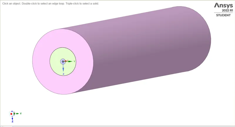
Due to limitations on the Academic License of ANSYS and considering the computing power and time it will take to simulate a flow on this mode. Instead, we will use a 2D axisymmetrical model derived from this model.
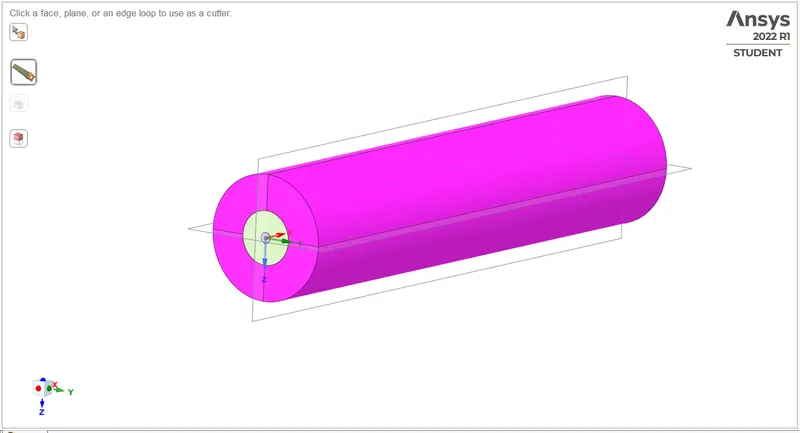
First, we split the combustor into four quarters:
Then, we extract one quarter from it, removing other parts:
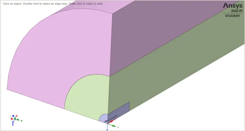
Then, we copy the surface from this cut part which forms our final profile:

MESHING:
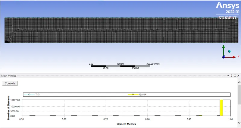
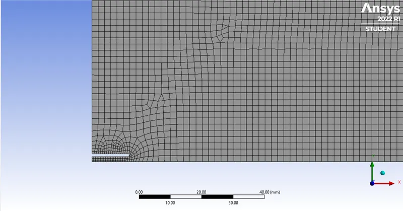
The mesh has an element size of 2mm with proximity capturing turned on:
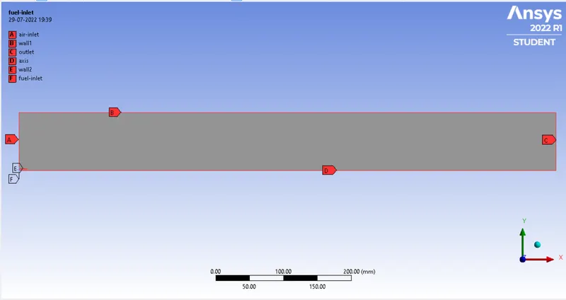
Boundaries:
SETUP:
General Setup:
Solver: Pressure-Based, Steady State, Axisymmetric Solver, Energy Equation Enabled
Viscous Model: K-epsilon model
Boundary Conditions: v = 0.5 m/s for air inlet, v = 80 m/s for fuel inlet
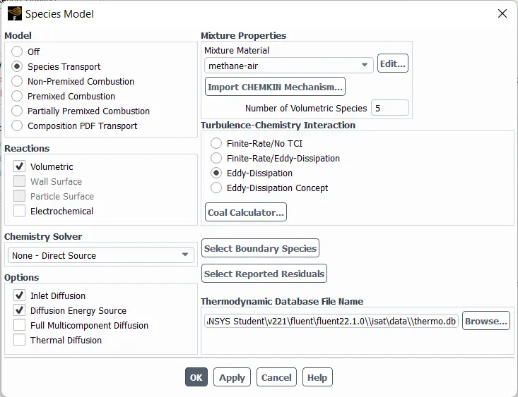
Since we are monitoring the reactants and products as well as pollutants that will be produced along the way, we enable Species Model:
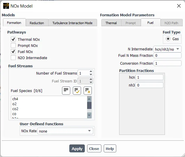
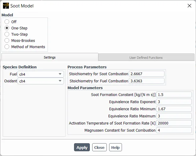
For Pollutants, we enable NOx and Soot Modelling:
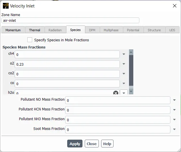
We need to set species mass fractions for boundary conditions as well:
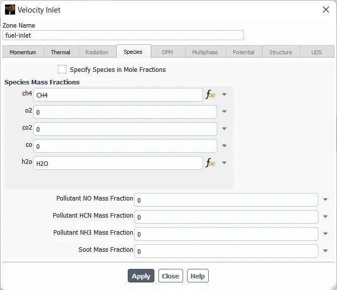
We will parameterize the fuel mass fractions to vary the water content in fuel:
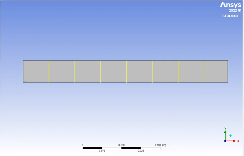
Lastly, we set up some line probes to measure the mass fractions across the combustor width:
RESULTS:
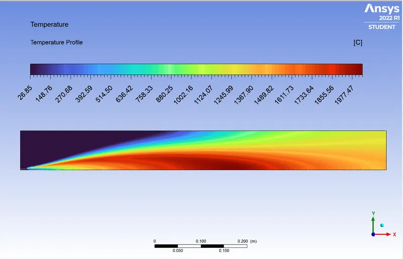
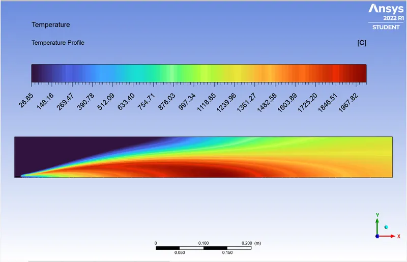
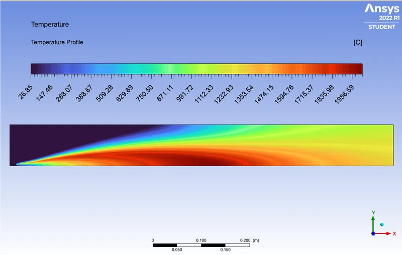
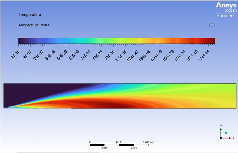
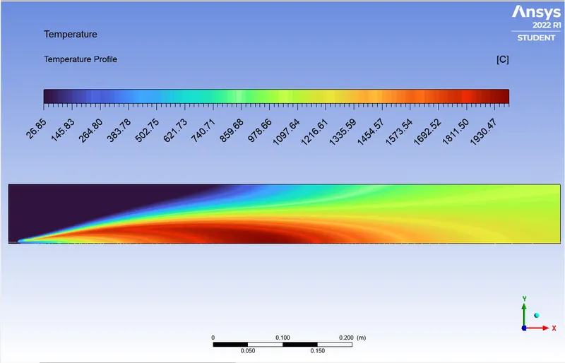
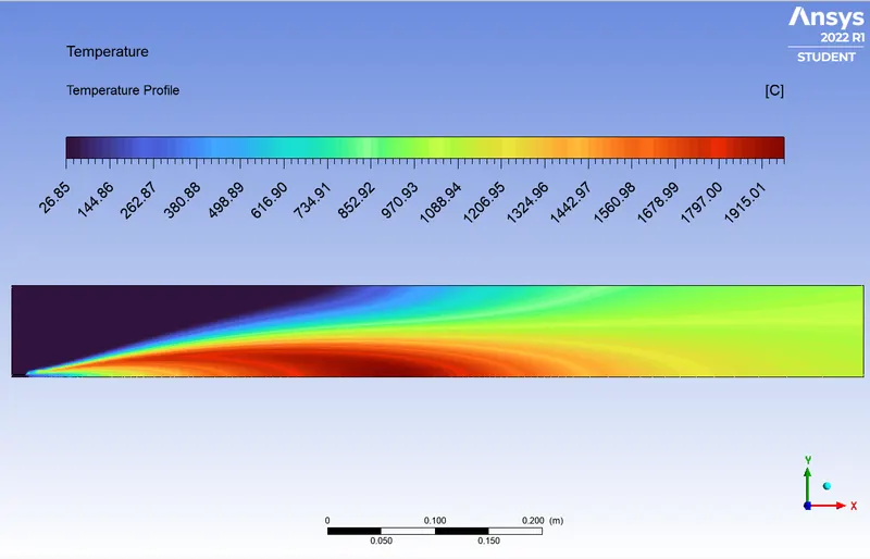
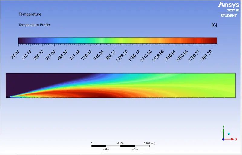
Temperature Profile:
0% Water Content:
5% Water Content:
10% Water Content:
15% Water Content:
20% Water Content:
25% Water Content:
30% Water Content:
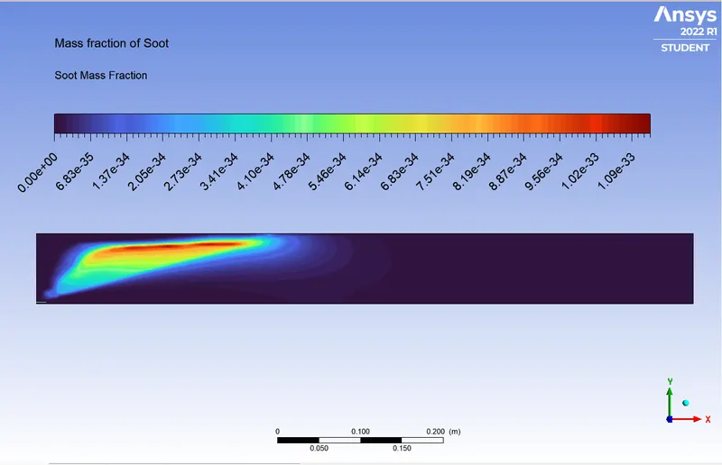
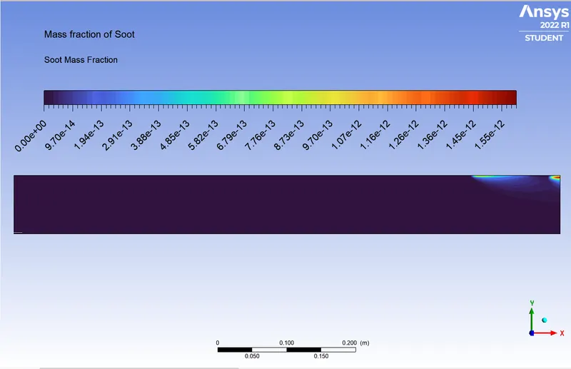
Soot Mass Fraction:
0% Water Content:
5% Water Content:
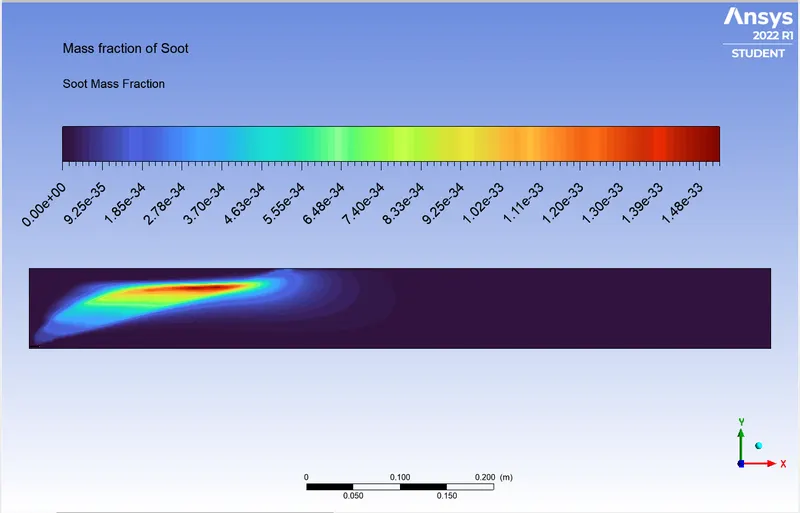
10% Water Content:
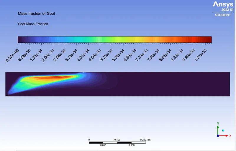
15% Water Content:
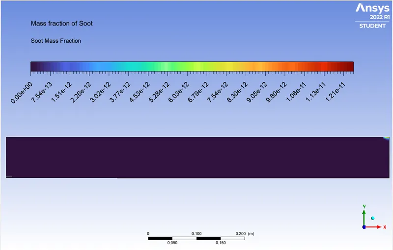
20% Water Content:
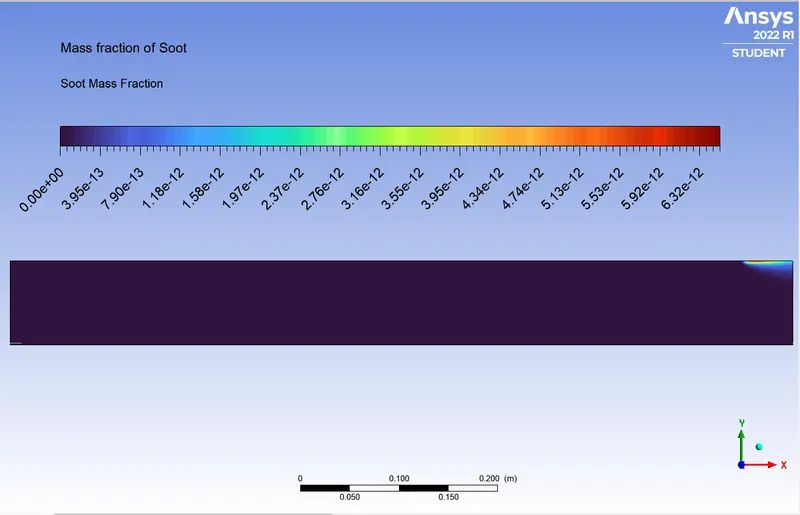
25% Water Content:
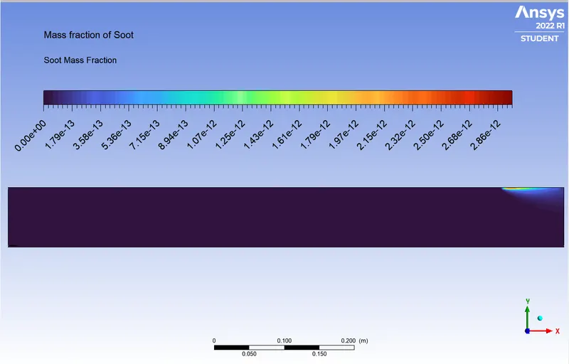
30% Water Content:
Oxygen Mass Fraction:
0% Water Content:
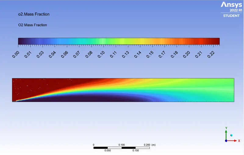
5% Water Content:
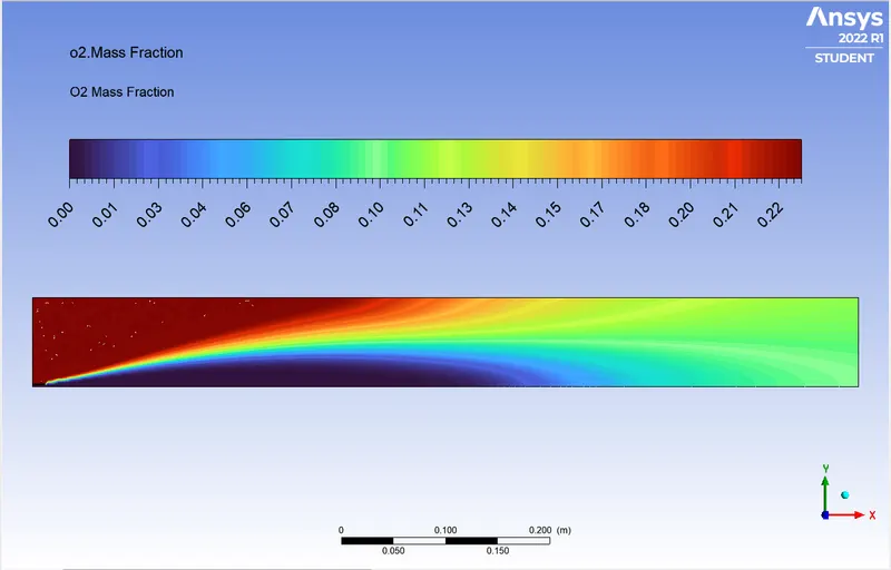
10% Water Content:
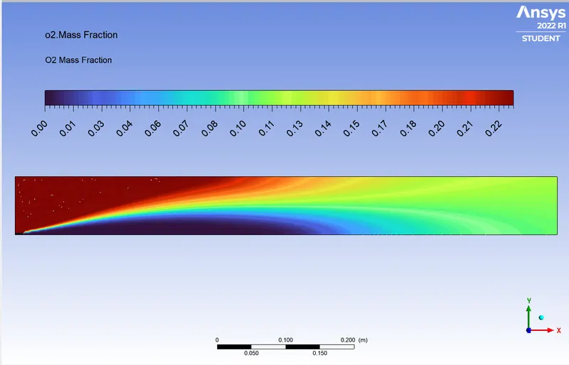
15% Water Content:
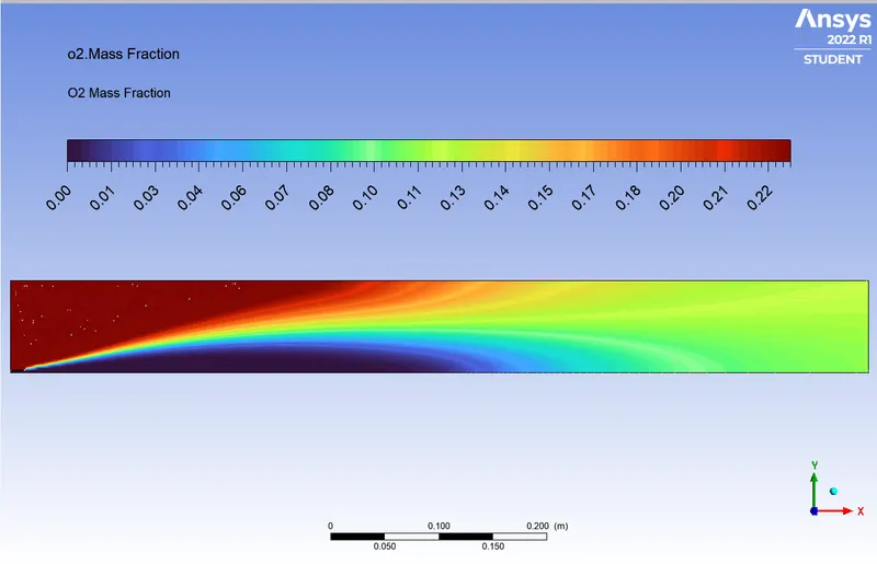
20% Water Content:
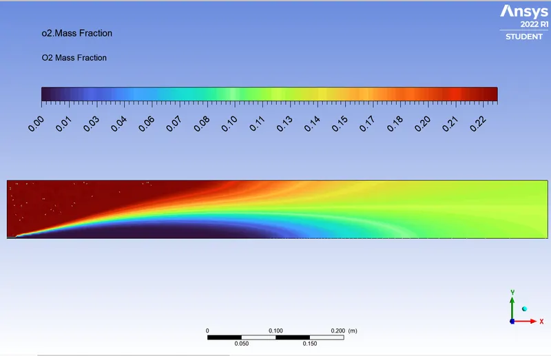
25% Water Content:
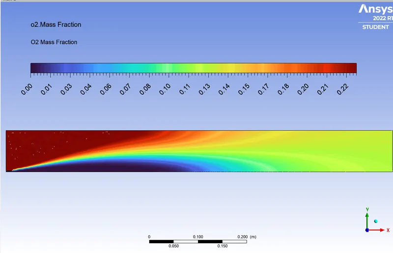
30% Water Content:
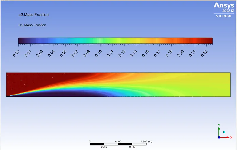
NO Mass Fraction:
0% Water Content:
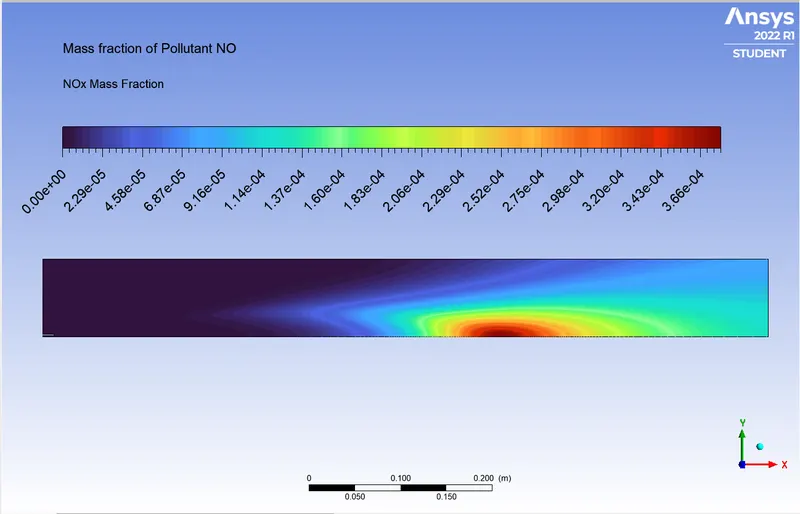
5% Water Content:
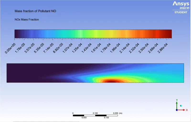
10% Water Content:
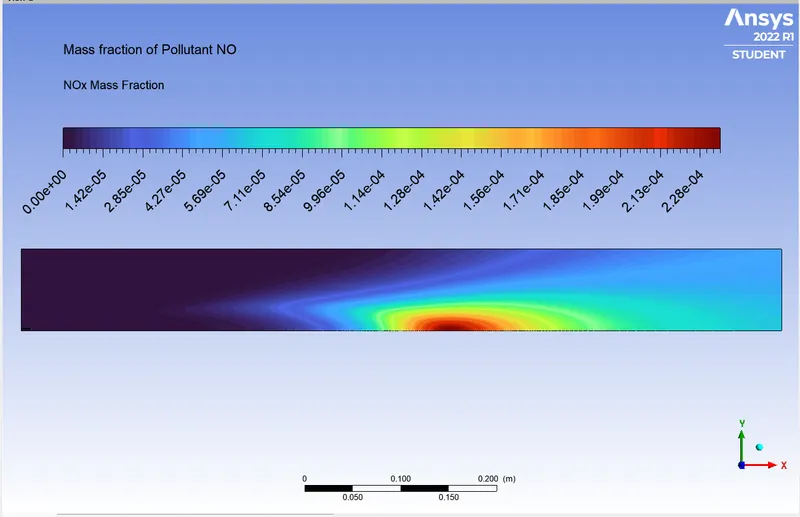
15% Water Content:
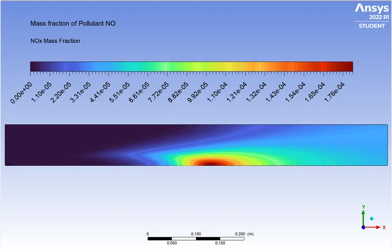
20% Water Content:
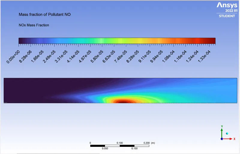
25% Water Content:
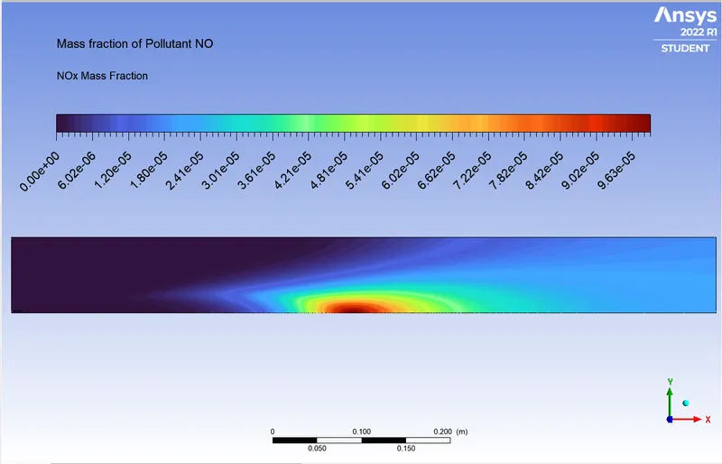
30% Water Content:
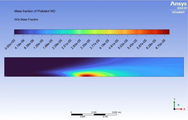
N2 Mass Fraction
0% Water Content:
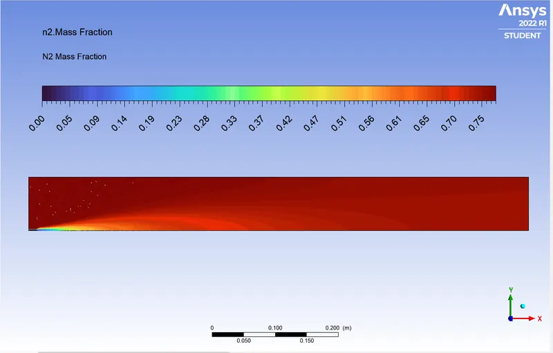
5% Water Content:
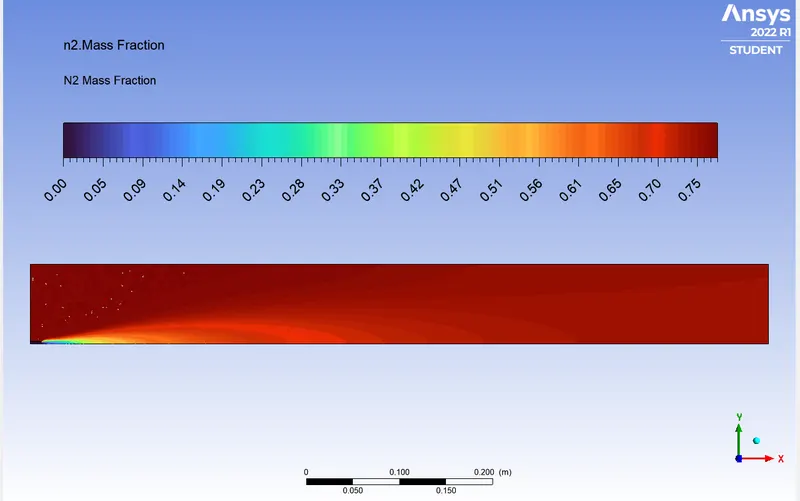
10% Water Content:
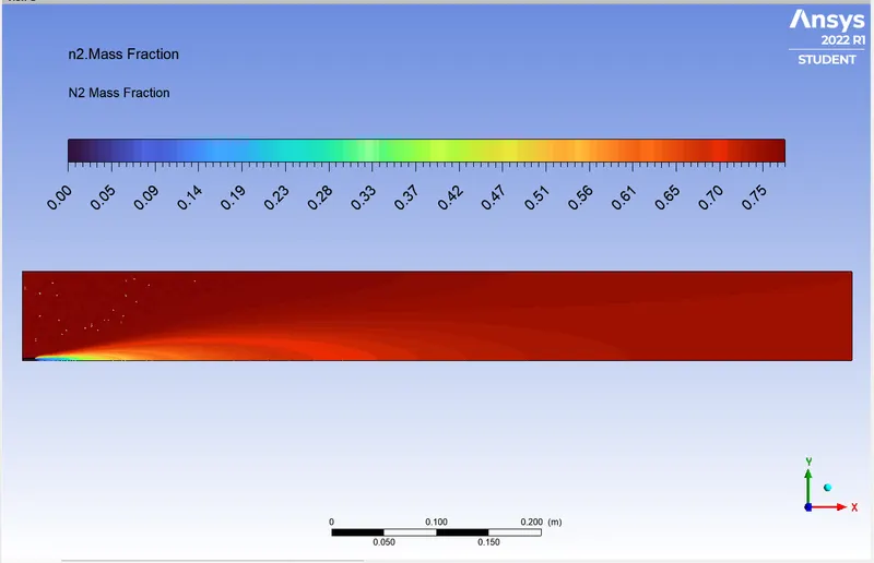
15% Water Content:
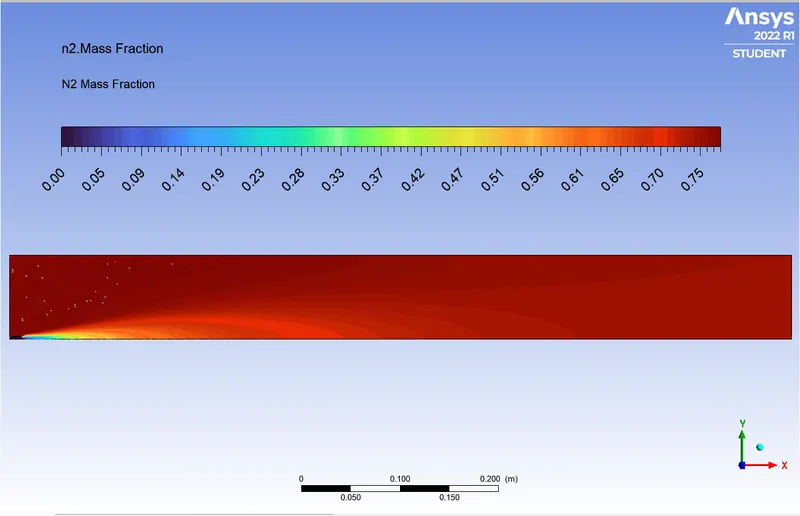
20% Water Content:
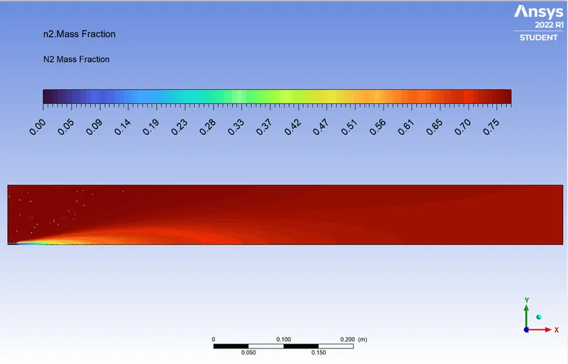
25% Water Content:
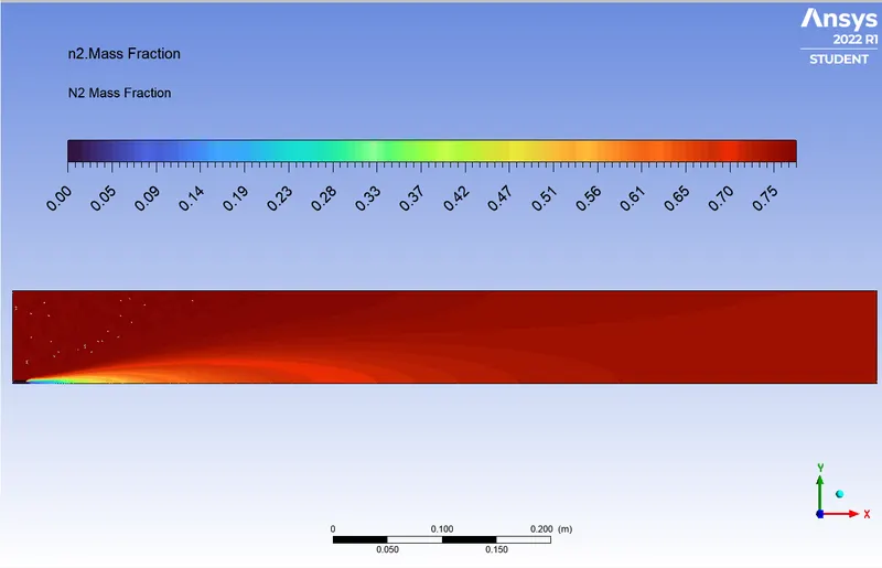
30% Water Content:
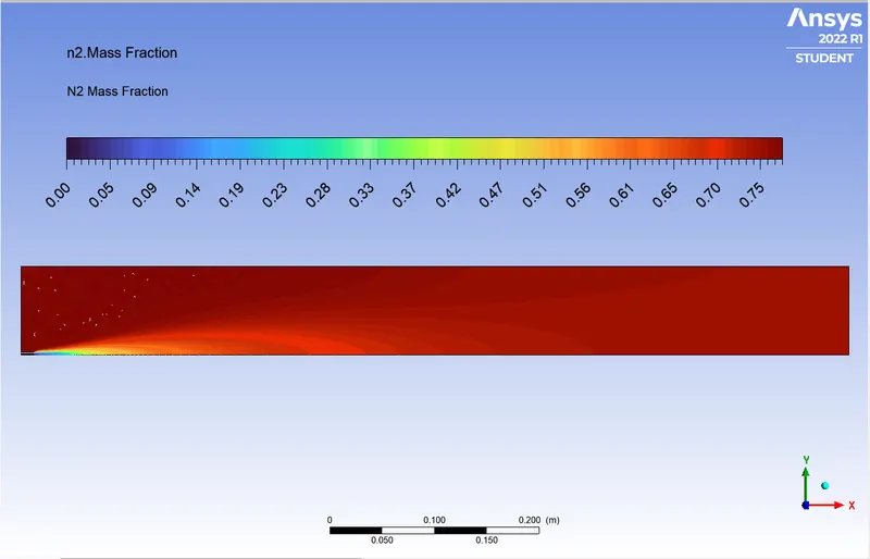
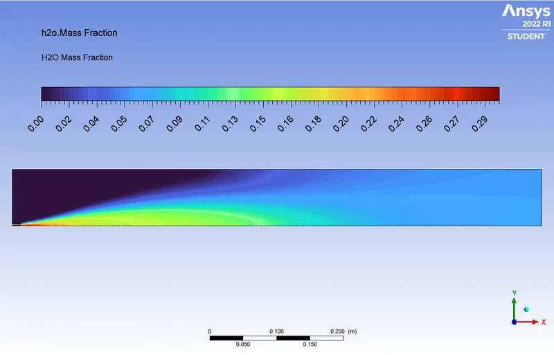
H2O Mass Fraction:
0% Water Content:
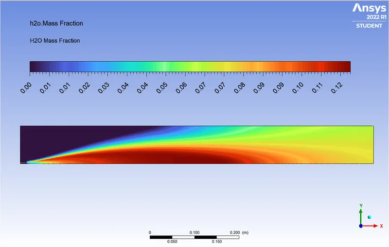
5% Water Content:
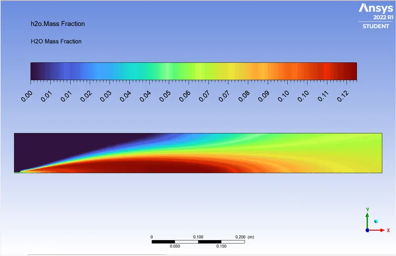
10% Water Content:
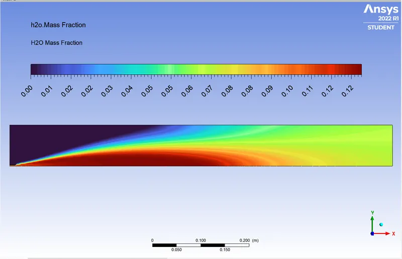
15% Water Content:
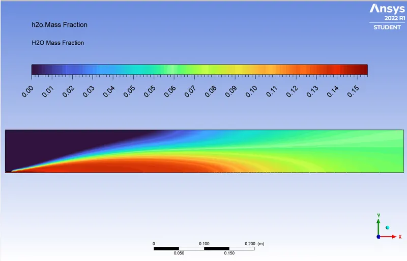
20% Water Content:
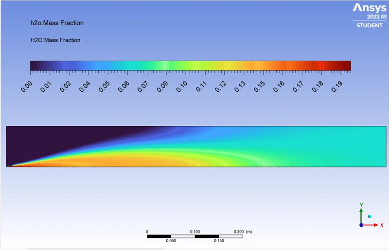
25% Water Content:
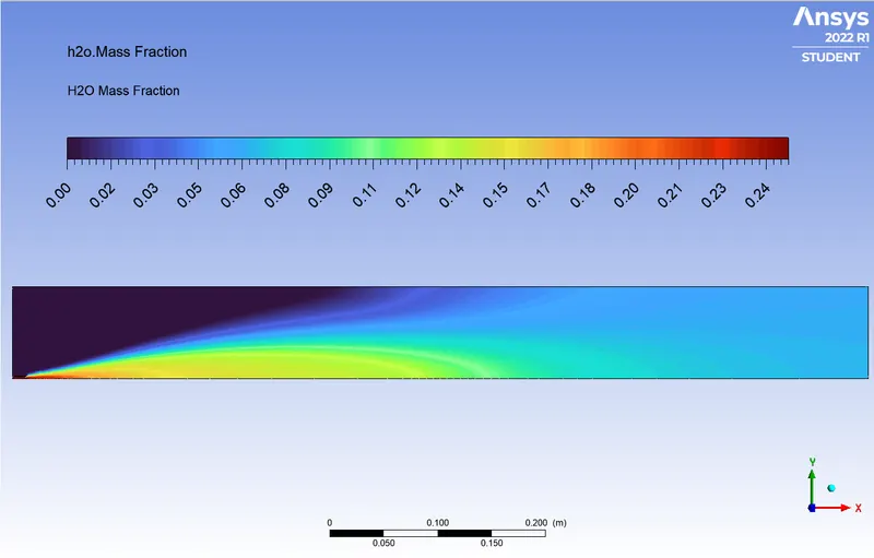
30% Water Content:
CO2 Mass Fraction:
0% Water Content:
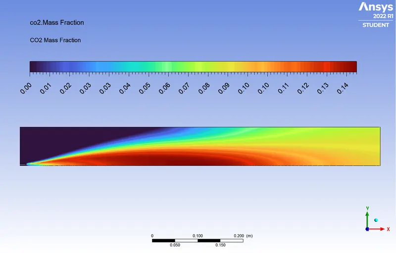
5% Water Content:
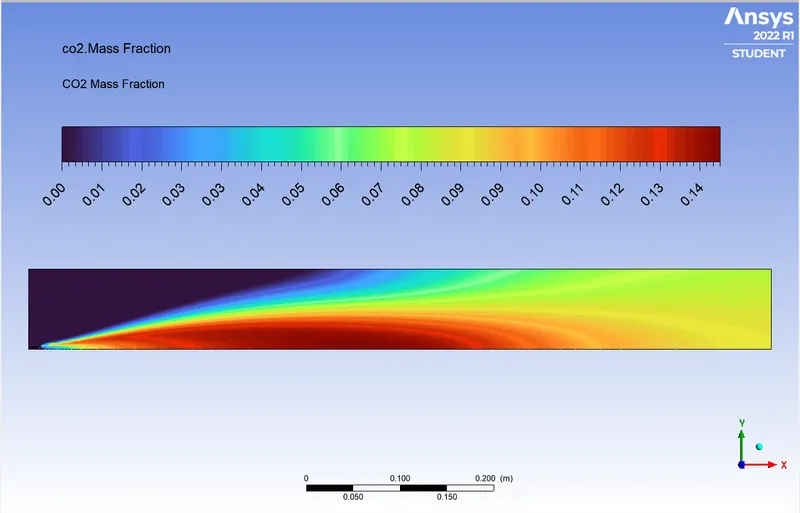
10% Water Content:
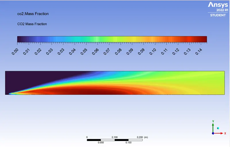
15% Water Content:
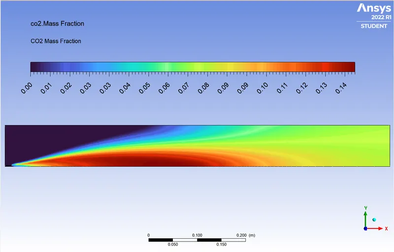
20% Water Content:
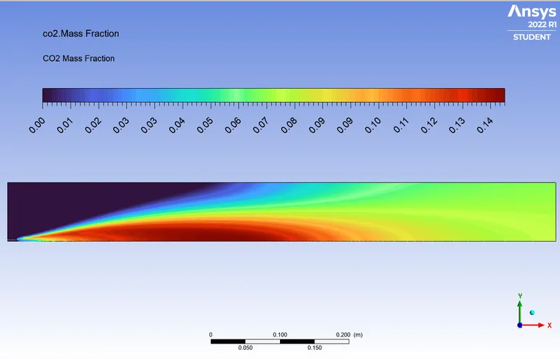
25% Water Content:
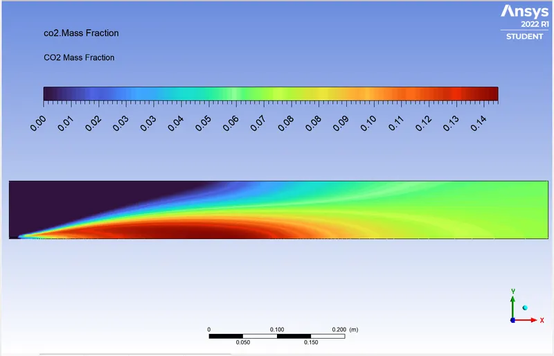
30% Water Content:
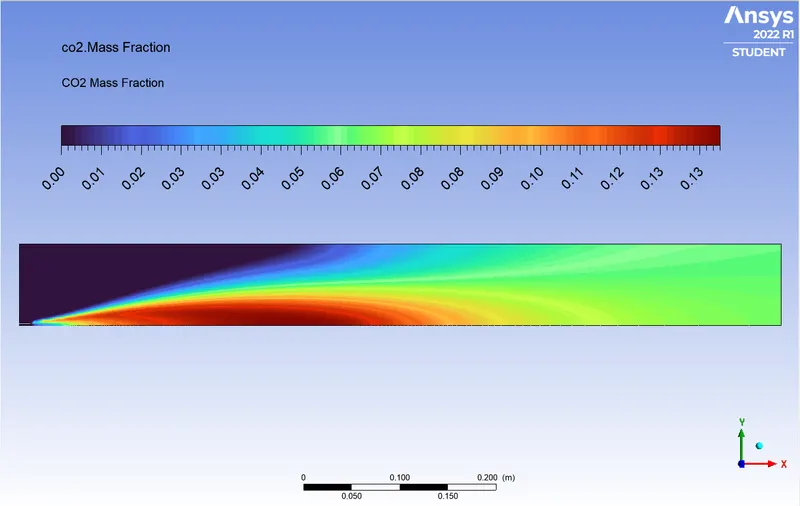
CH4 Mass Fraction:
0% Water Content:
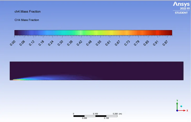
5% Water Content:
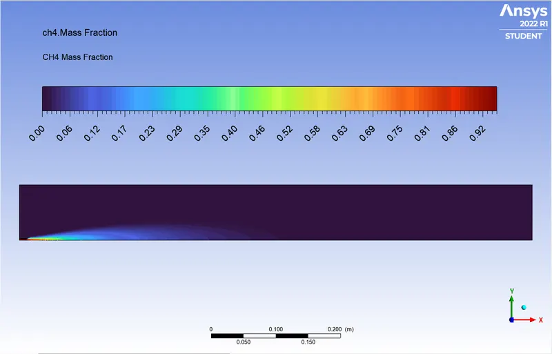
10% Water Content:
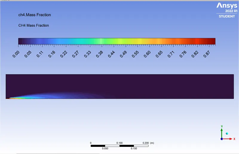
15% Water Content:
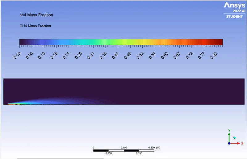
20% Water Content:
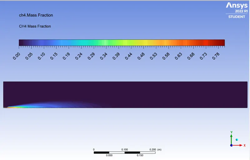
25% Water Content:
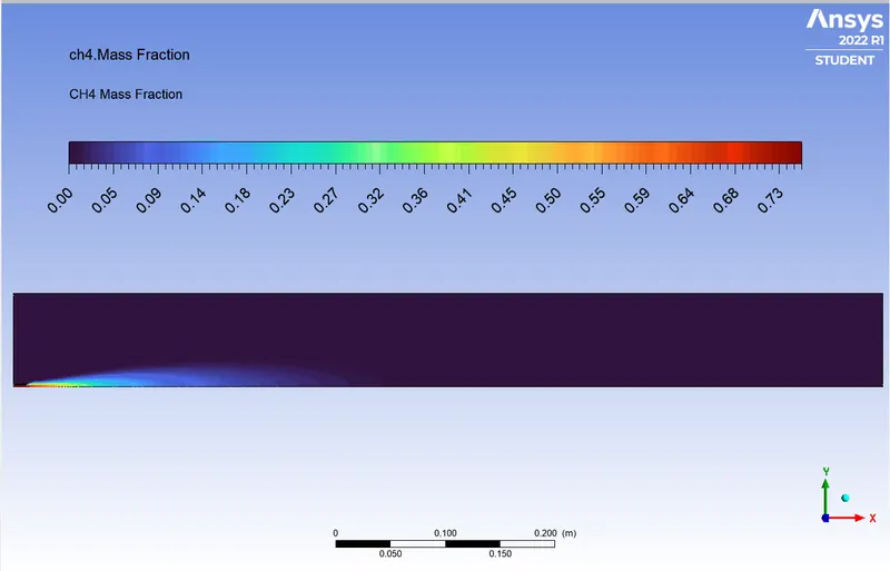
30% Water Content:
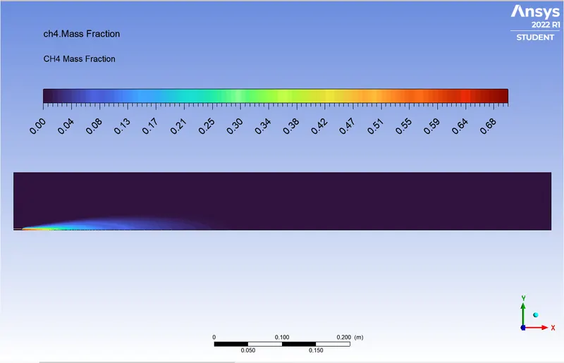
NO Concentration Chart:
0% Water Content:
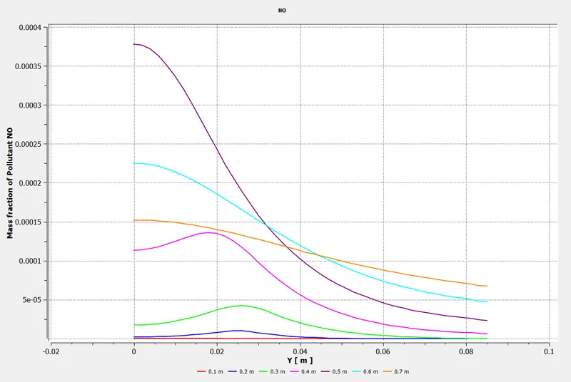
5% Water Content:
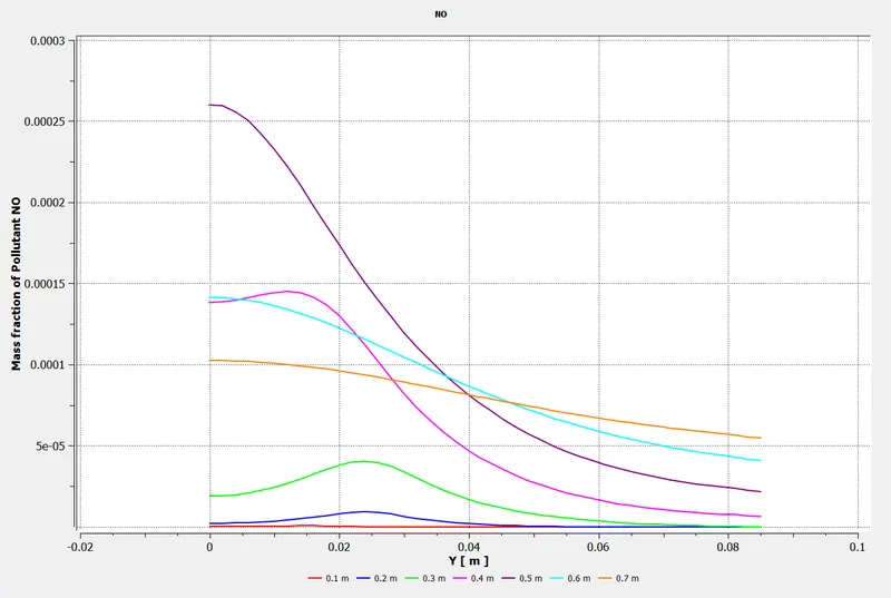
10% Water Content:
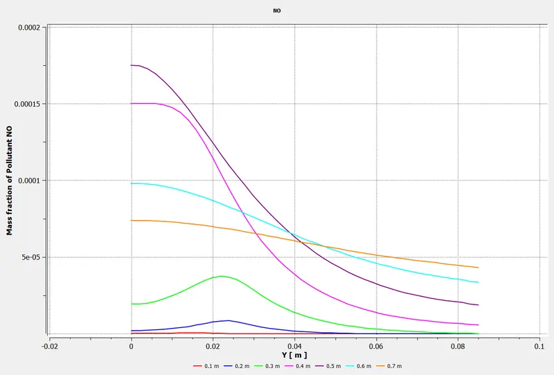
15% Water Content:
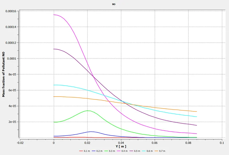
20% Water Content:
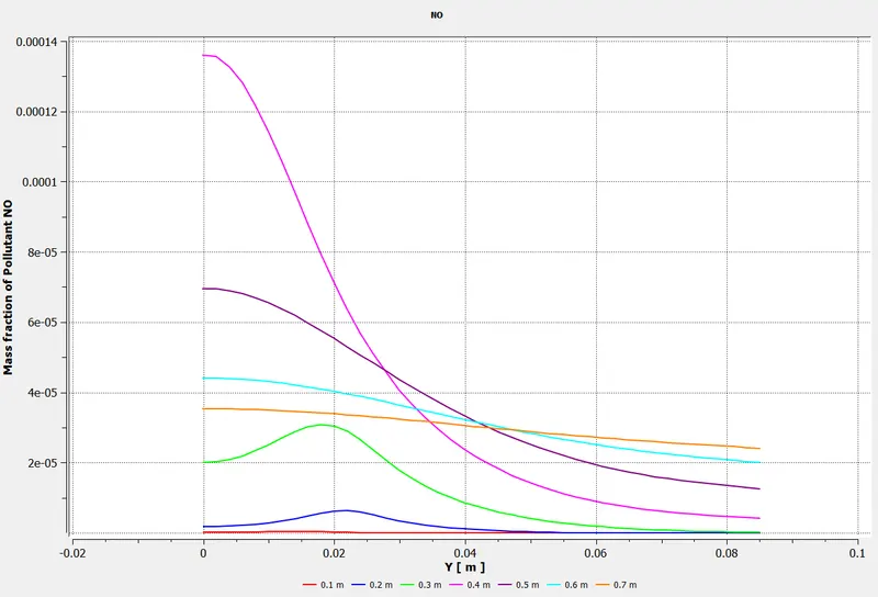
25% Water Content:
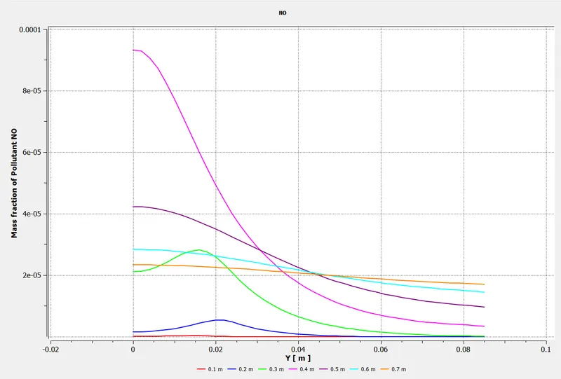
30% Water Content:
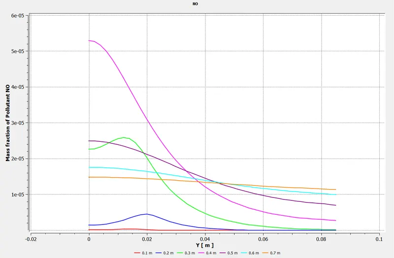
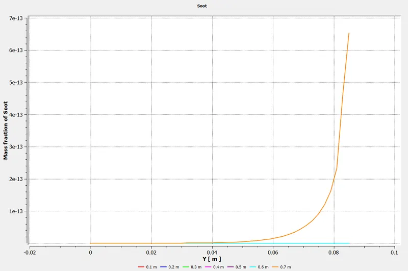
Soot Concentration Chart:
0% Water Content:
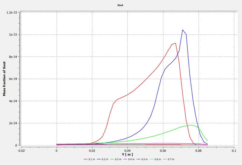
5% Water Content:
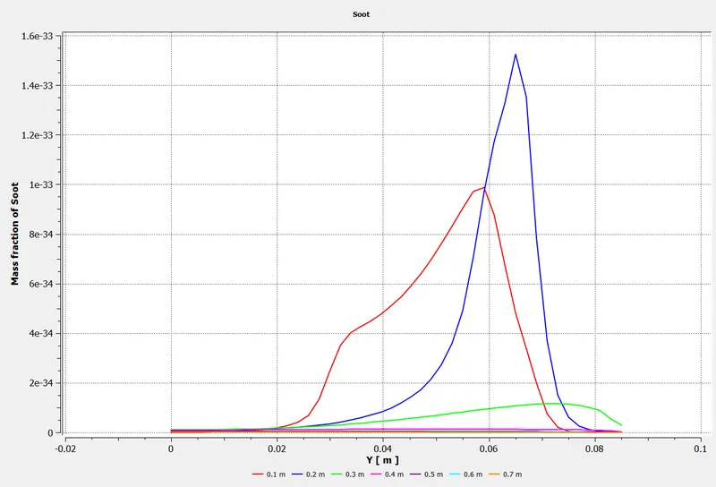
10% Water Content:
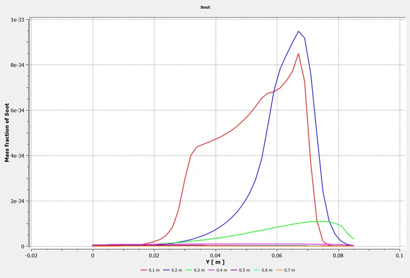
15% Water Content:
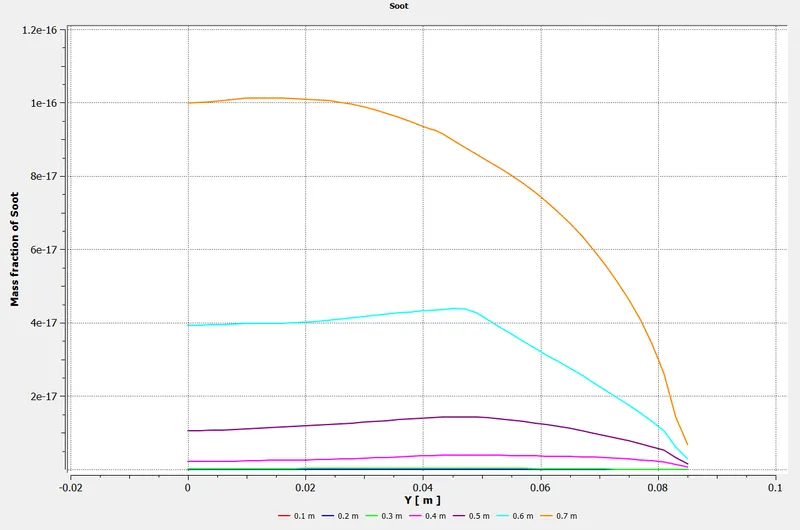
20% Water Content:
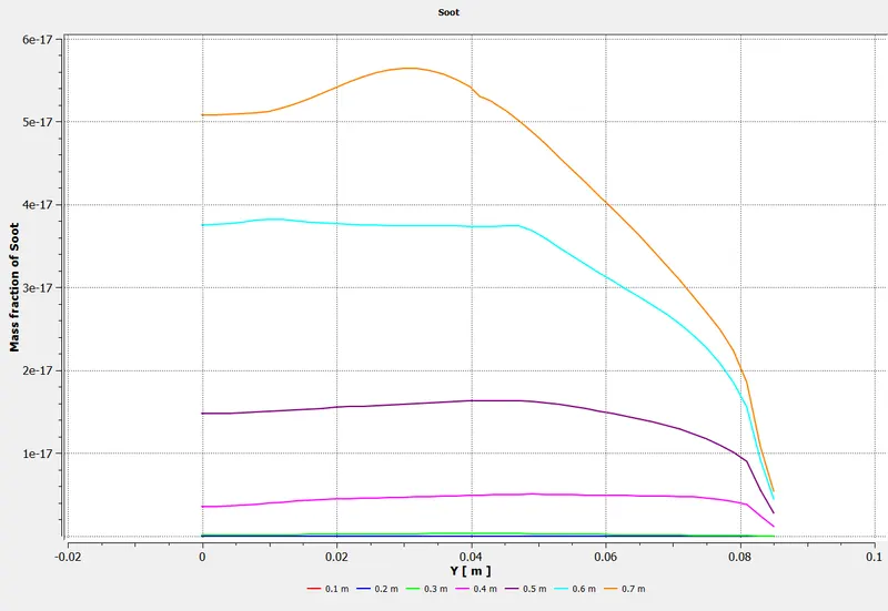
25% Water Content:
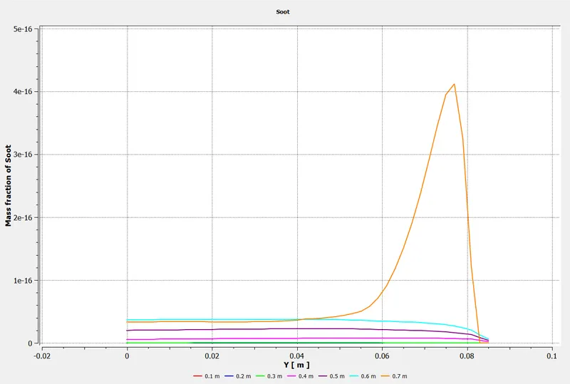
30% Water Content:
CH4 Concentration Chart:
0% Water Content:
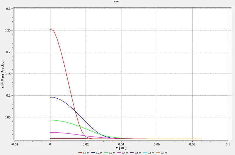
5% Water Content:
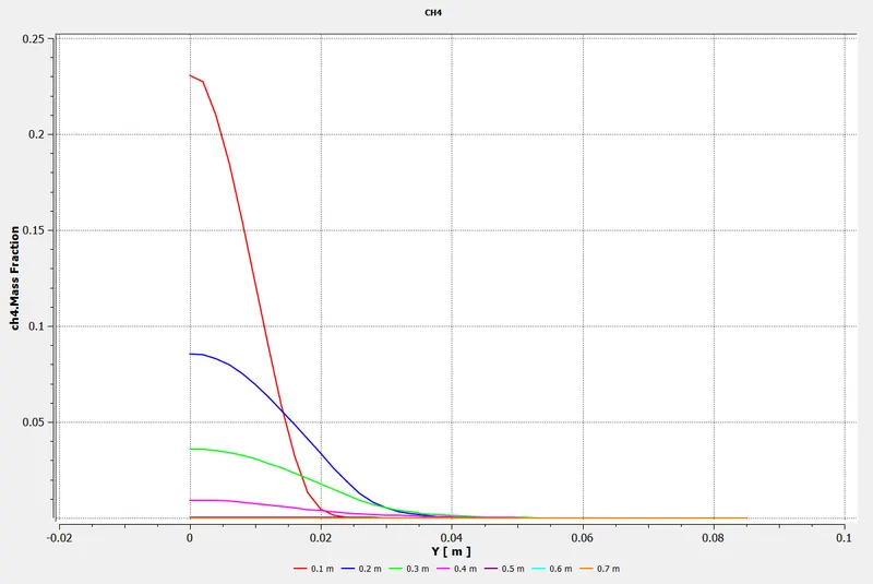
10% Water Content:
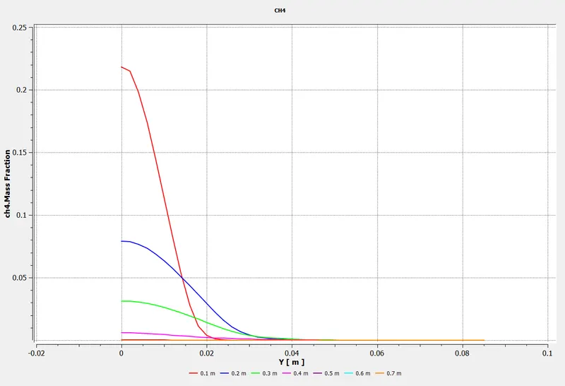
15% Water Content:
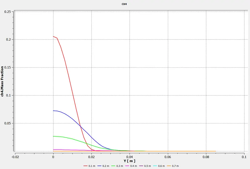
20% Water Content:
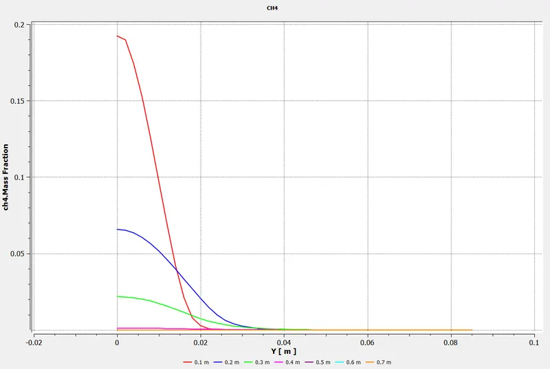
25% Water Content:
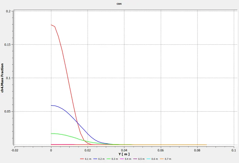
30% Water Content:
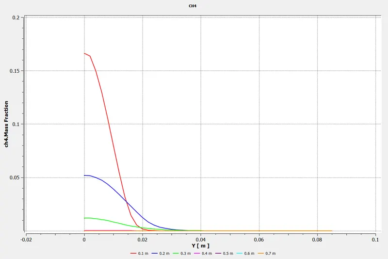
CO2 concentration Chart:
0% Water Content:
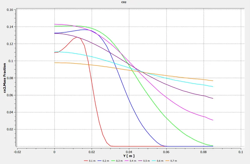
5% Water Content:
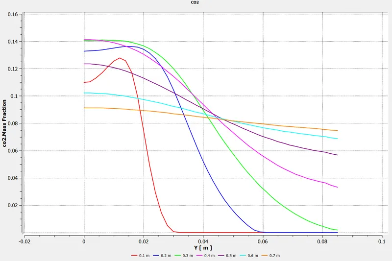
10% Water Content:
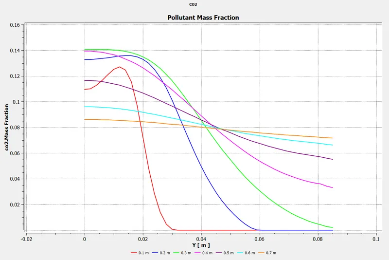
15% Water Content:
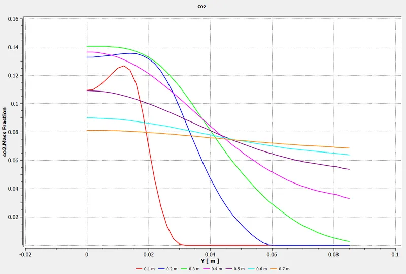
20% Water Content:
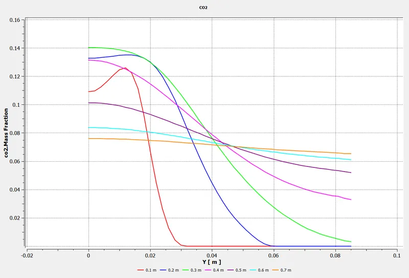
25% Water Content:
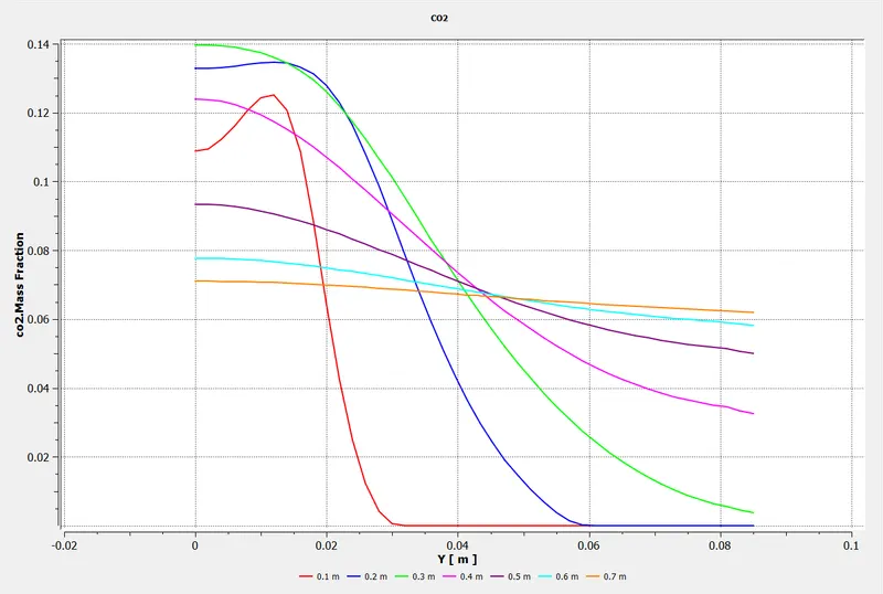
30% Water Content:
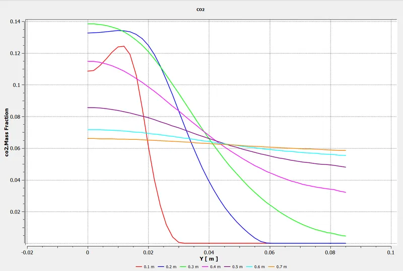
H2O Concentration Chart:
0% Water Content:
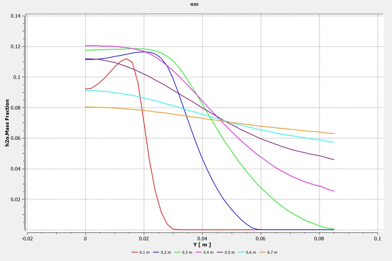
5% Water Content:
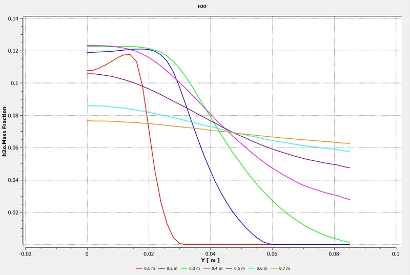
10% Water Content:
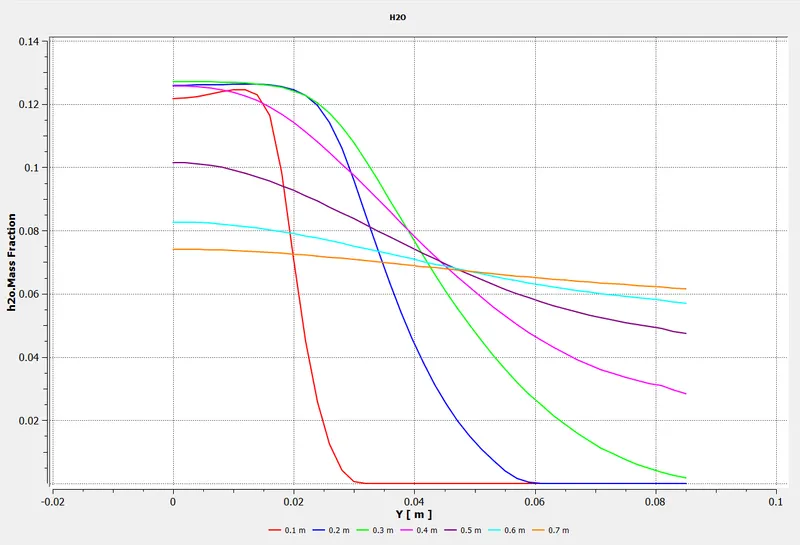
15% Water Content:
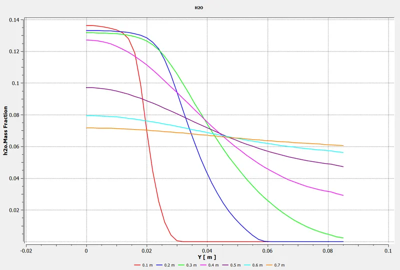
20% Water Content:
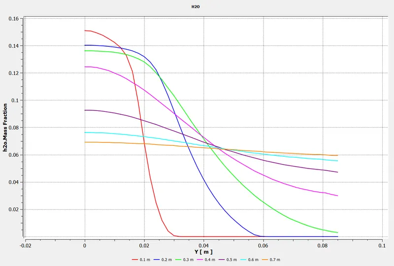
25% Water Content:
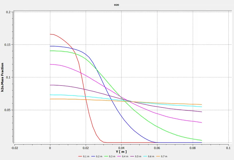
30% Water Content:
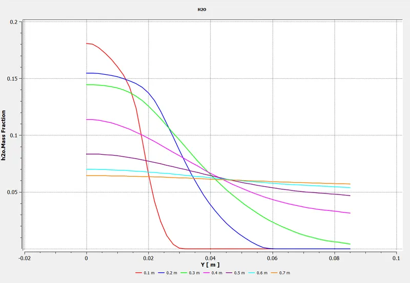
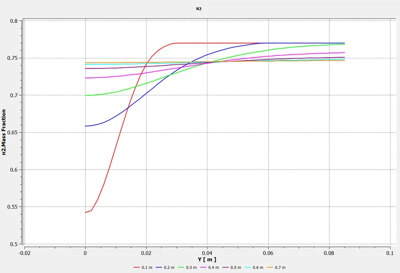
N2 Concentration Chart:
0% Water Content:
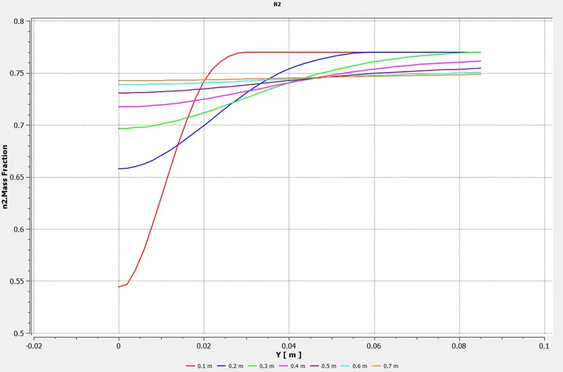
5% Water Content:
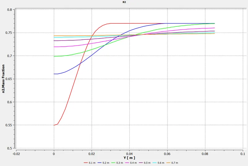
10% Water Content:
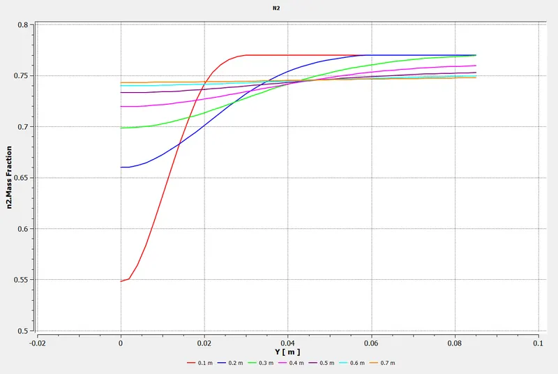
15% Water Content:
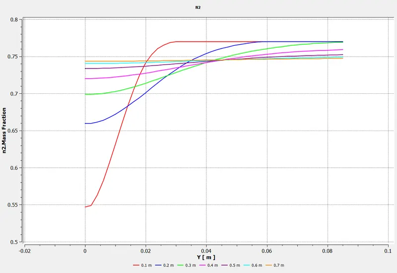
20% Water Content:
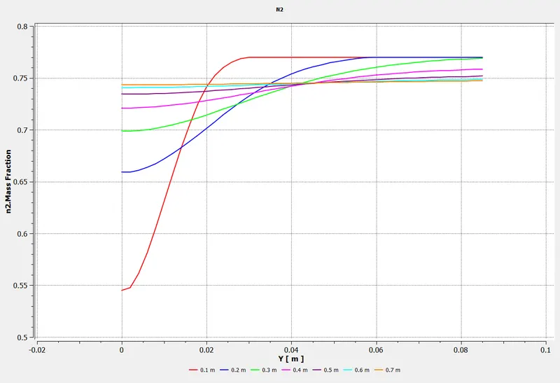
25% Water Content:
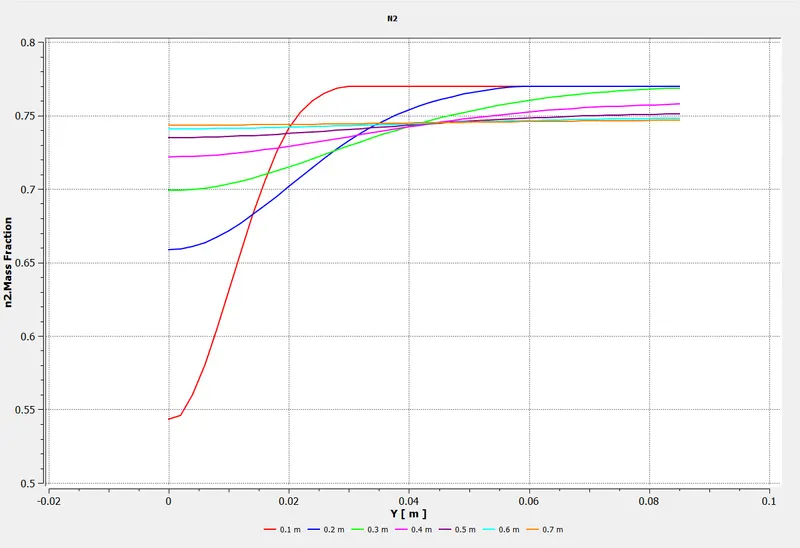
30% Water Content:
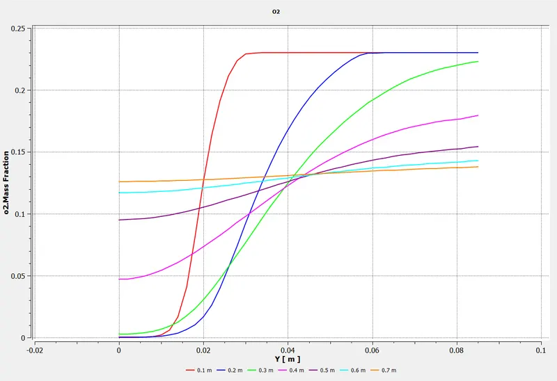
O2 Concentration Chart:
0% Water Content:
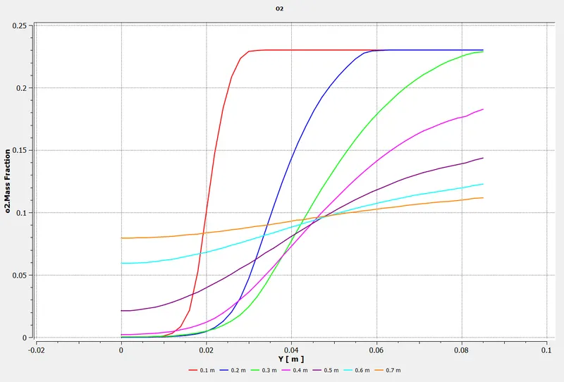
5% Water Content:
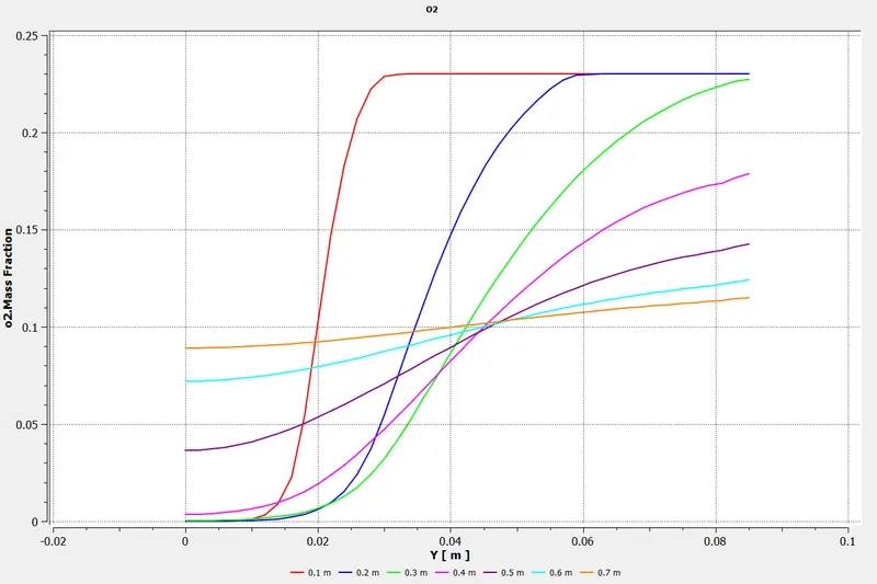
10% Water Content:
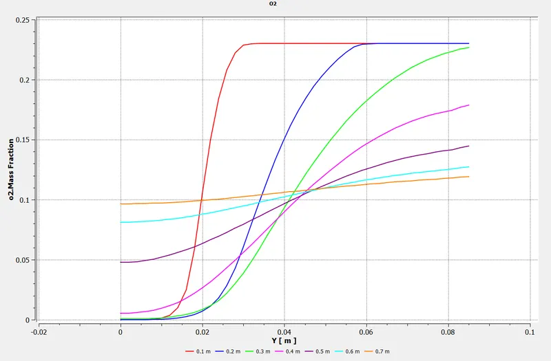
15% Water Content:
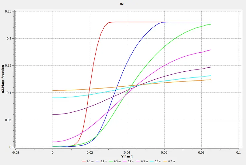
20% Water Content:
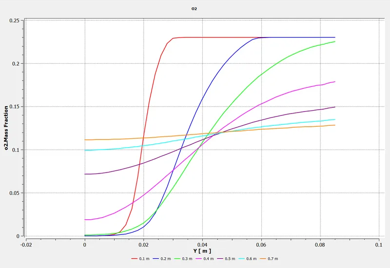
25% Water Content:
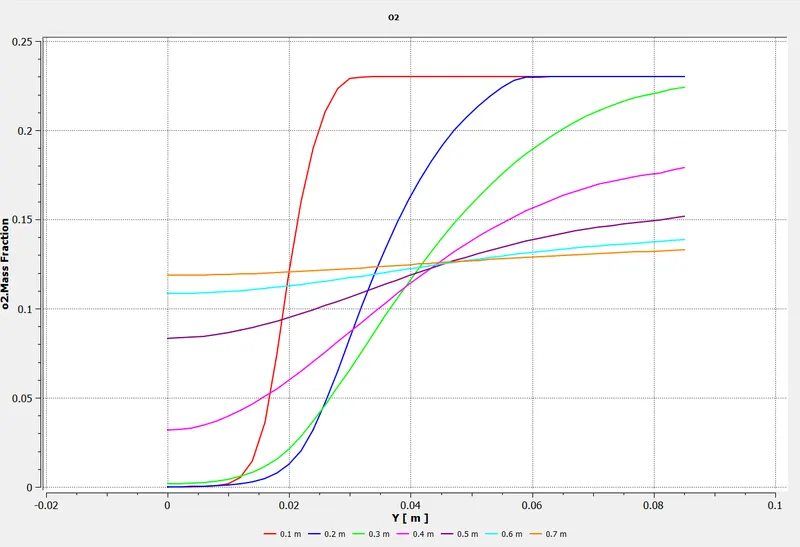
30% Water Content:
CONCLUSION:
Following inferences can be made from this comprehensive study:
- Adding water content decreases the concentration of pollutants NO and Soot. The decrease is proportional to the amount of water added.
- Water content also decreases the maximum temperature in the combustor by almost 100K.
- An important aspect is that increasing the water content moves the high concentration zones toward the middle of the combustor, and the high concentration zone of soot towards the outlet.
- There is however negligible change in concentrations of CO2, N2 and O2.
- This is a desirable effect as the NO pollutants leaving the combustor have very low concentrations.
- Similarly, deposited soot will be easier to clean up if it is near outlet.