Week 10 - Simulating Combustion of Natural Gas.
#) Objective of the project -1) To simulate the process of combustion on a model using the fuel and air.
2) Plot the variation of mass fraction of different species in the simulation using line probes at the different locations of the model.
1) Introduction of combustion- Combustion, or burning, is a high-temperature exothermic redox chemical reaction between a fuel (the reductant) and an oxidant, usually atmospheric oxygen, that produces oxidized, often gaseous products, in a mixture termed as smoke. Combustion does not always result in fire, because a flame is only visible when substances undergoing combustion vaporize, but when it does, a flame is a characteristic indicator of the reaction. While the activation energy must be overcome to initiate combustion (e.g., using a lit match to light a fire), the heat from a flame may provide enough energy to make the reaction self-sustaining.
Combustion manifests as awode domain during the design , analysis and performance characteristics stage by being an integral part of various internal combustion engines and furnaces and power station combustors.
2) Combustion models for the CFD analysis-
3) Combustion models for CFD refers to combustion models for computational fluid dynamics. Combustion is defined as a chemical reaction in which a hydrocarbon fuel reacts with an oxidant to form products, accompanied with the release of energy in the form of heat. Being an integral part of various engineering applications like internal combustion, aircraft engines, rocket engines, furnaces, and power system combustions, combustion manifests itself as a wide domain during the design, analysis, and performance characteristics stages of the above-mentioned applications.
The model should be competent enough to deliver information related to species concentration their volumetric concentration, volumetric generation or destruction rates and changes in parameters like enthalpy, temperature and mixture density.
#) Combustion based on mixing-
1) Nonpremixed combustion - In non-premixed combustion, fuel and oxidizer enter the reaction zone in distinct streams. This is in contrast to premixed systems, in which reactants are mixed at the molecular level before burning. Examples of non-premixed combustion include pulverized coal furnaces, diesel internal combustion engines, and pool fires. Many practical
combustion devices, such as furnaces, steam boilers, diesel engines, liquid rocket motors, and
gas turbine engines, involve turbulent non-premixed combustion. In these devices, mixing
occurs by a combination of turbulent stirring of the fuel and oxidizer streams and molecular
diffusion. Turbulence greatly enhances the mixing process by increasing the surface area of the
thin mixing layers where most of the molecular diffusion occurs.
2) Premixed combustion- In premixed combustion fuel and the oxidizer are mixed at the molecular level prior to ignition. Combustion occures as flame front propagating into the unburnt reactants.
examples of premixed combustion is the internal combustion engine lean-premixed gas, gas turbines and gas leak explosions.l
3) Partially premixed combustion- Partially premixed combustion system are premixed flames with non- uniform fuel oxidizer mixtures.
Such flames include premixed jets discharging into an inert atmosphere. Lean premixed combustors with diffusion pilot flame s , cooling air jets, and imperfectly mixed inlets.
#) Combustion based on phases-
1) Fluid phases(volumetric reaction)- Combustion takes place in flouid region.
2) wall (surface reaction)- Combustion takes place on the wall region.
3) Particles( surface reaction)- Combustion takes place on lagrangian particle. combustion of coal is an example.
4) Porous region- combustion takes place in the porous region and the reaction is an after-treatment system.
#) combustion reactions-
CH4+ar(O2+3.76N2) = aCO2+bH2o+cN2.
balancing the stoichiometric reaction we get-
a = 1 .
2b=4 so b = 2
2ar = 2a+ b so ar = 2
c = 15.04
The above values correspond to the number of moles of the given species
Fuel
Air- 2 moles of O2+ 7.52 moles of N2.
Therefore
Mole fractions
mole fractions of O2 = 2/(2+7.52) = 0.21
mole fraction of the N2 = 7.52/(7.52+2) = 0.79
#) mass fraction is
mass fraction of O2 = (0.21*16)/((0.21*16)+(0.79*14) = 0.23
mass fraction of N2 = 0.79*14/(0.21*16)+(0.79*14) = 0.77
part 1 - Combustion simulation to get the mass fraction of the CO2 , H2o , CH$ and others.
Part 2 - Adding watwer in fuel from 5 to 30 % by mole and observing the results of NOX emissions and the soot formation.
For fuel - use methane Air - 2 step as a mixture
For soot formation - use one step soot model
#) Geometric model of the combustion chamber that is being provided-
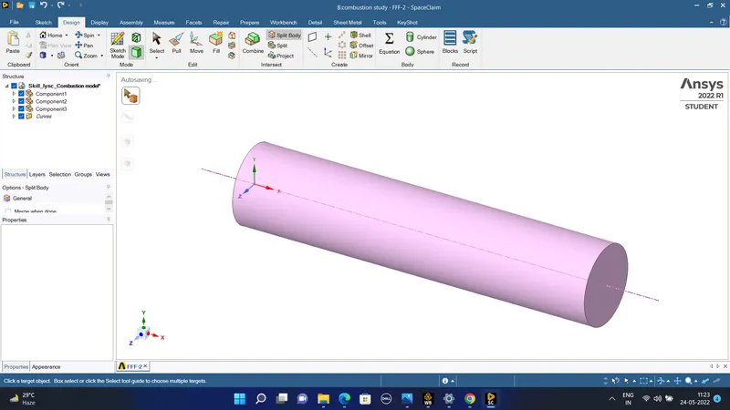
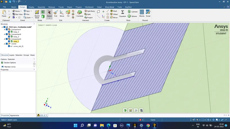
Now we have to convert this 3 D model to the 2D model in spaceclaim by the following procedure-
1) We will choose the plane option and include the planes in which we would cut or split the body to produce new 2 dimensional body.
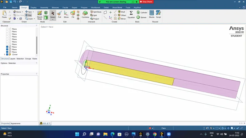
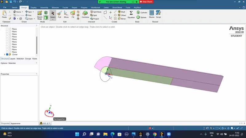
#) We would use the split body option and then copy the body of the 2 dimensions and paste itg into a new design to create a 2- dimensional object-
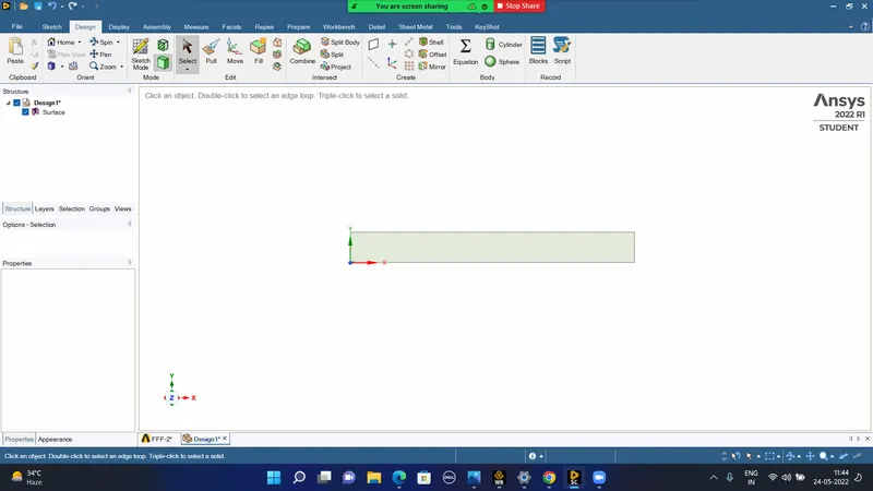
#) Now we go to mesh to create the mesh of he rectangular 2- dimensional domain-
#) Now in mesh we create the mesh by the following characteristics of mesh-
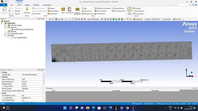
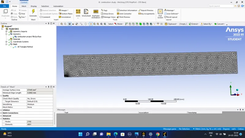
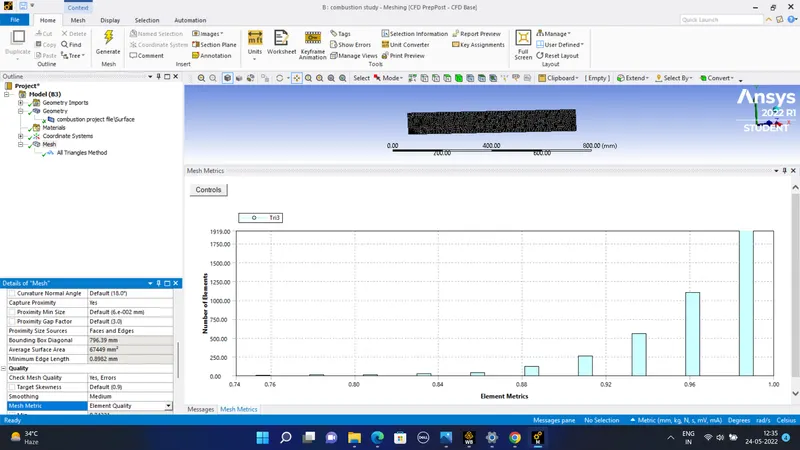
The number of nodes = 2182
The number of elements = 4001
the orthogonal quality and the skewness o0f the mesh is also shown-
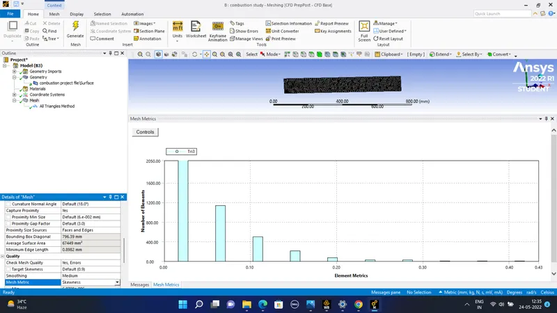
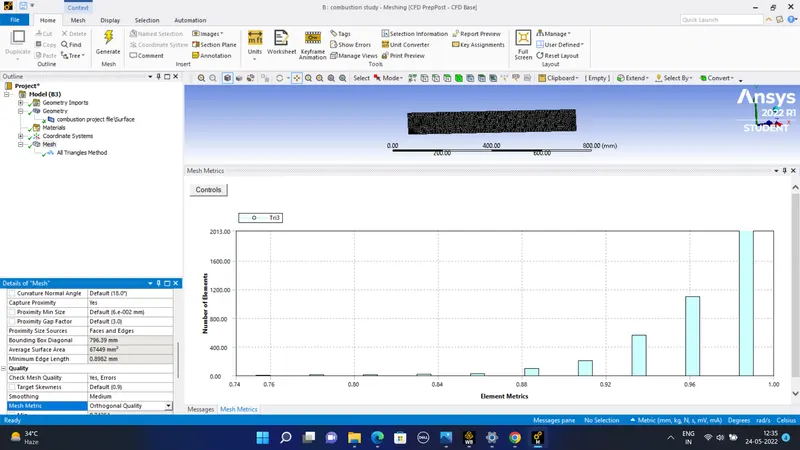
#)All triangle method was used this gave the shape of each element as triangle which is useful for combustion simulation
#) Case setup - Pressure-based solver.
Solver type- steady state solver.
Viscous model- k-epsilon.
energy equation - enabled.
The species model is -
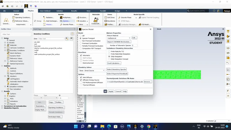
#) The Boundary conditionss given are as follows-
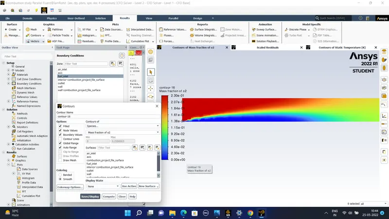
Air inlet = velocity = 0.5 m/sec.
Temperature = 300 k.
Species-
CH4 = 0
O2 = 0.23
CO2 = 0
H2O = 0
Fuel inlet = 80 m/sec
Temperature = 300 k
Species-
CH4 = 1
O2 = 0
carbon dioxide(C02) = 0
water(H2O) = 0
Top surface wall is given as the wall boundary condition.
Axis -
x-axis - axisymmetric type .
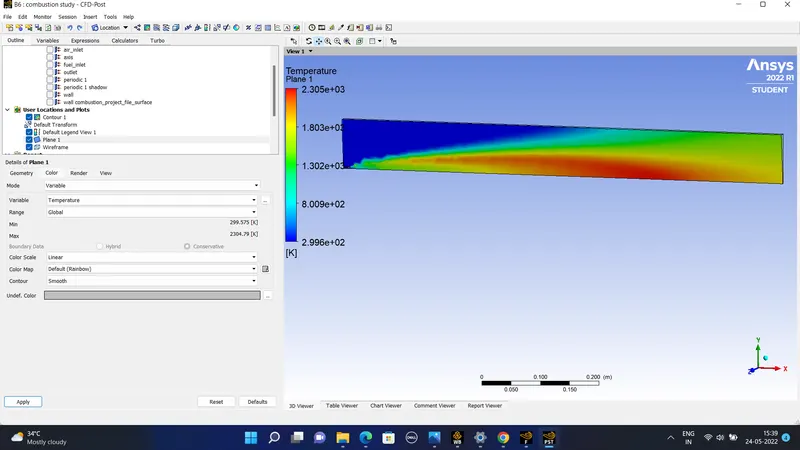
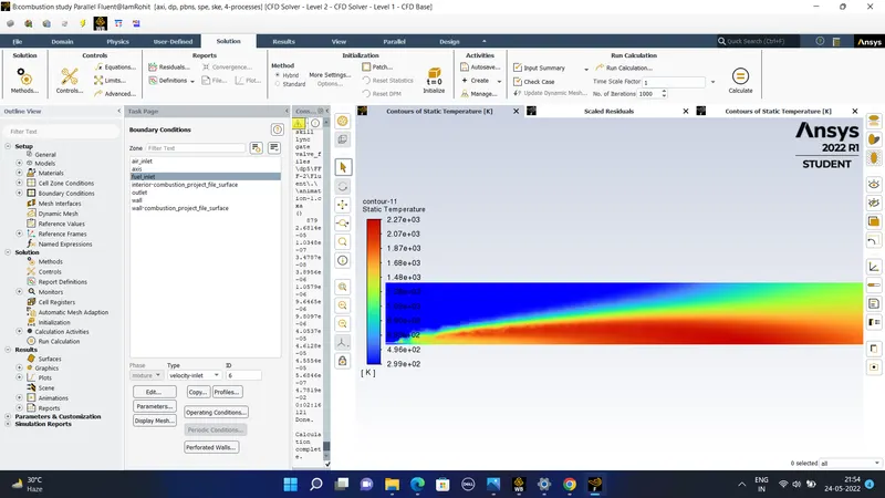
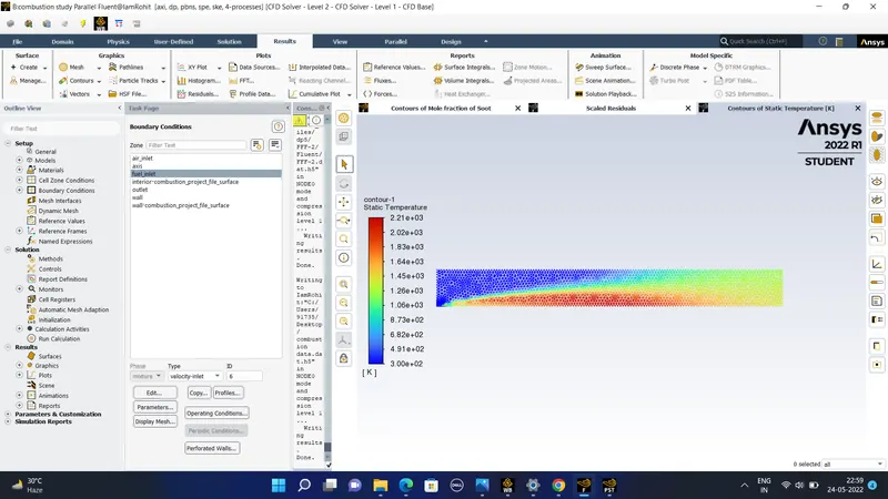
#) After doing hybrid initialization the following contour of static temperature is obtained-
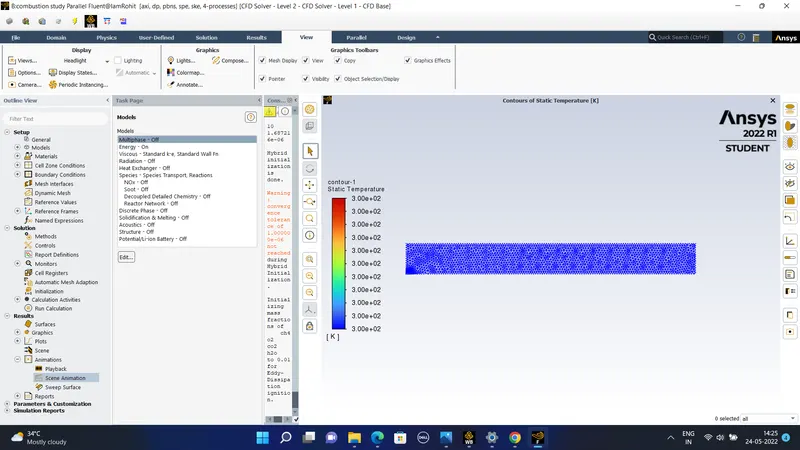
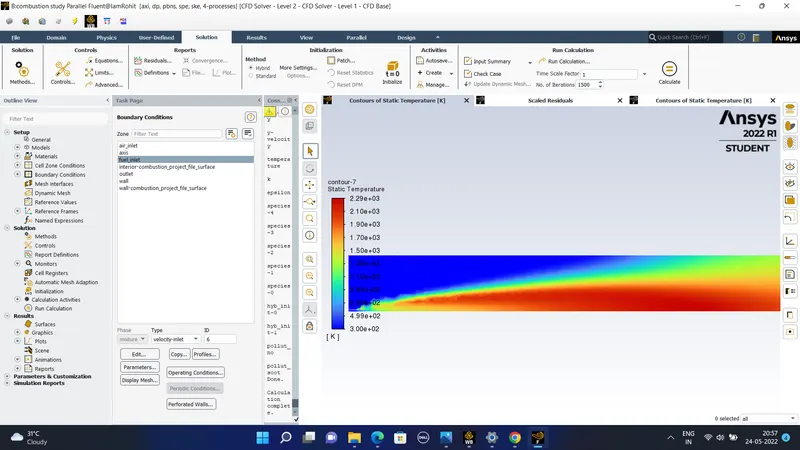
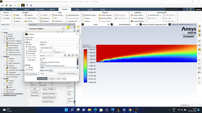
The final contours of stataic temperature obtained after 1500 iterations are-
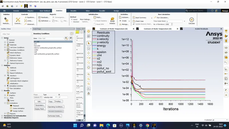
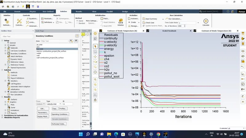
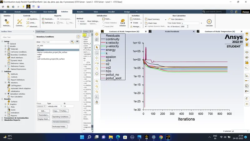
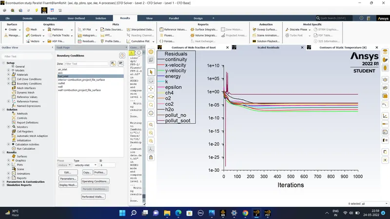
The residuals plot obtained after soot formation is made on-
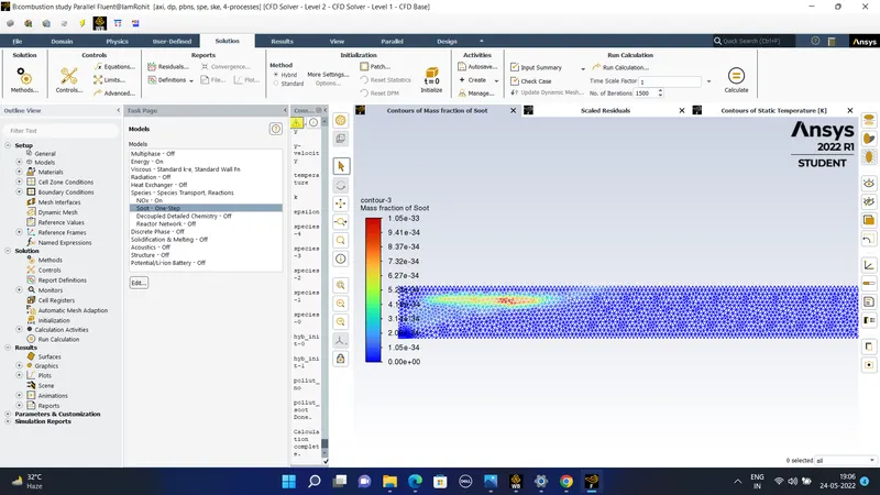
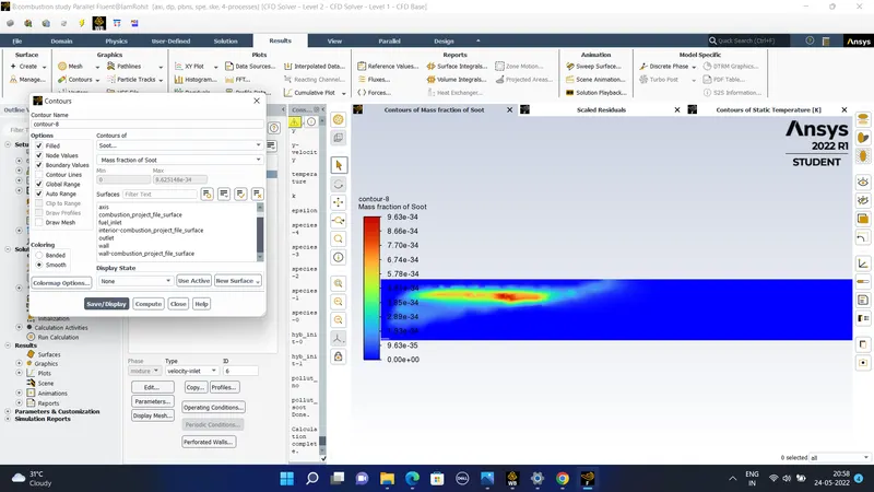
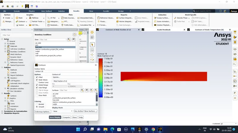
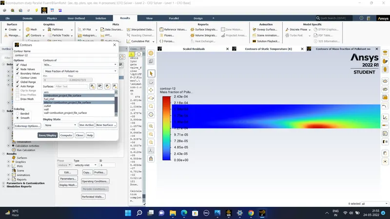
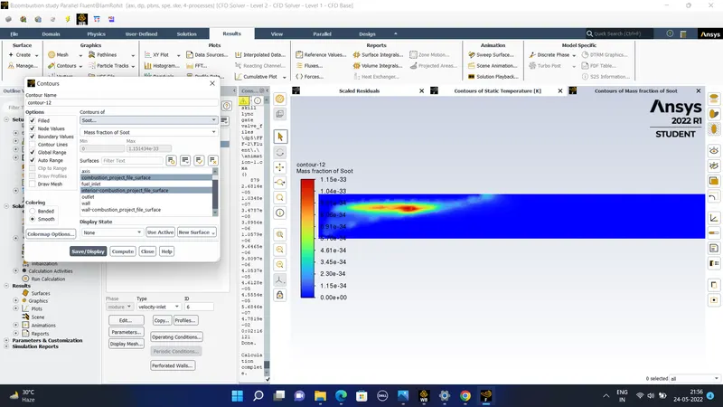
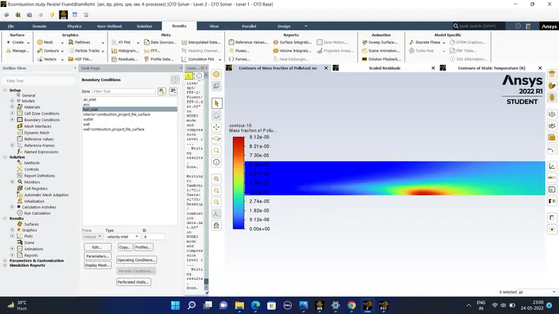
The contours of the soot and the pollutant like the NOx is of -
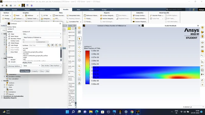
The geometry and the mesh generated are the same for the case 1 and case 2 except for the mass fraction of species in air-inlet and the fuel-inlet. The NOx model is turned on which helps to determine the pollution formation . The NOx formation takes place by the oxidation procesws of the air which acts as the oxidiser, hence thermal NOx is formed. The prompt NOx enabled as the high speed reaction at the flame front causes NOx formation.
The one soot model is made on as it helps to find out the rate of soot formation based on simple empirical model.
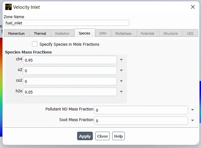
In part 1 the mass fraction of H2o is 0 and CH4 is 1 and in part 2 he mole fraction of H2o is increased from 5% to 30%
#) Observations from part 1 wer get-
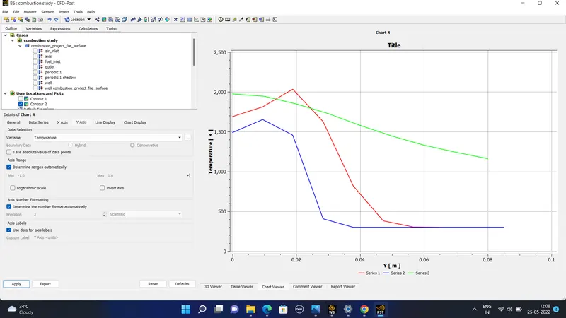
1) In the temperature contour it can be seeen that the highest temperature is observed ahead of the inlet of combustor where the mixing of fuel air mixture takes place.
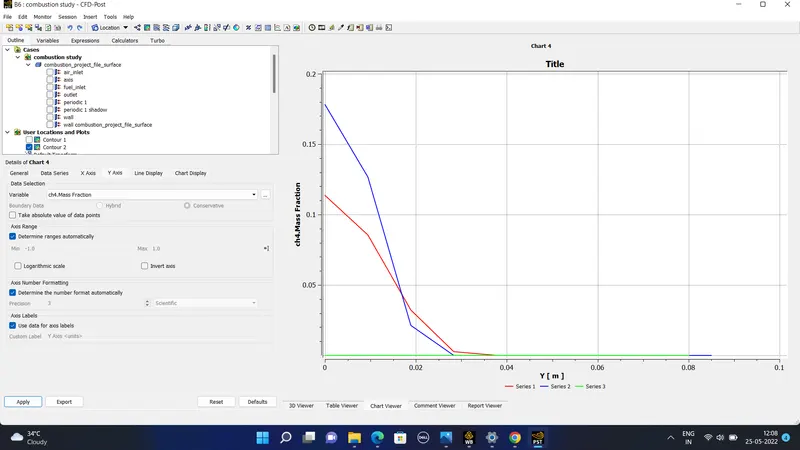
2) In the CH4 mass fraction contour the highest mass fraction of CH4 is observed near the fuel inlet where the fuel is discharged and as combustion takes place CH4 mass fraction decreases.
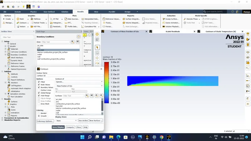
3) Highest mass fraction of CO2 and H2O is observed in the high temperature zone.
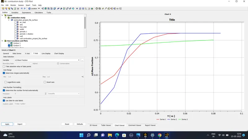
4) From the N2 mass fraction contour it can be seen that N2 is alomost distributed uniformly.
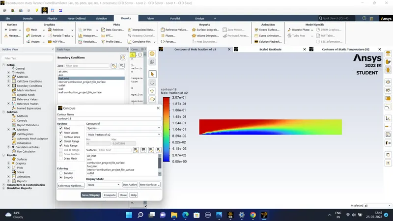
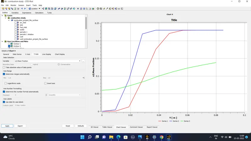
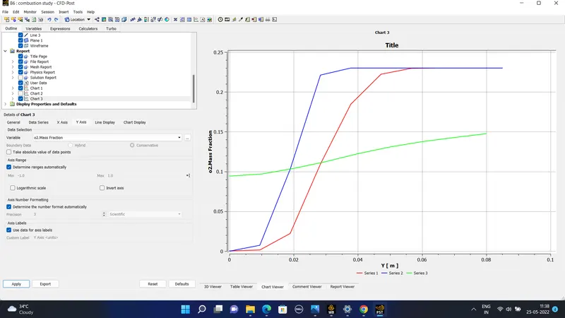
5) The oxygen mass fraction is highest near the air inlet.
6) The pollutant like NOx and soot mass fraction is more near the outlet of the combustor.
#) Case 2-
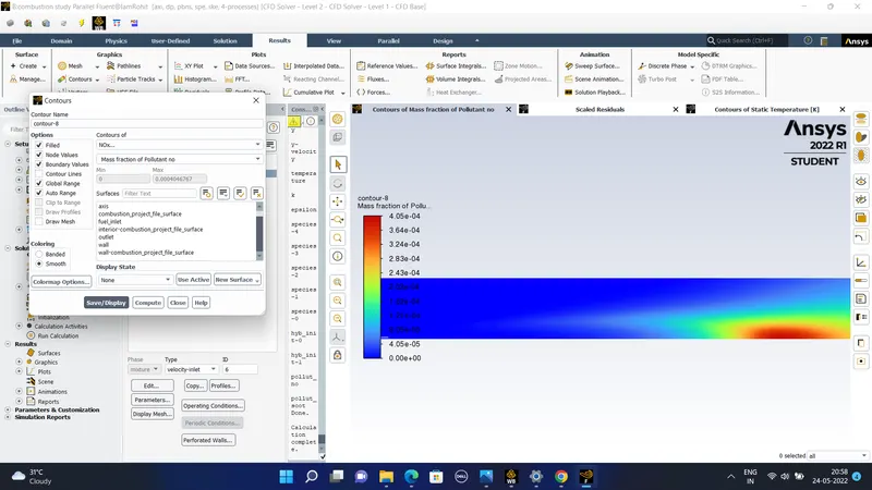
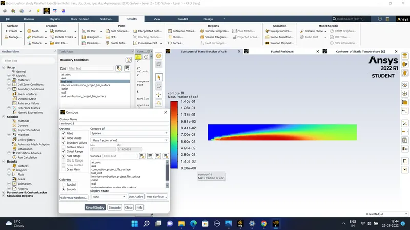
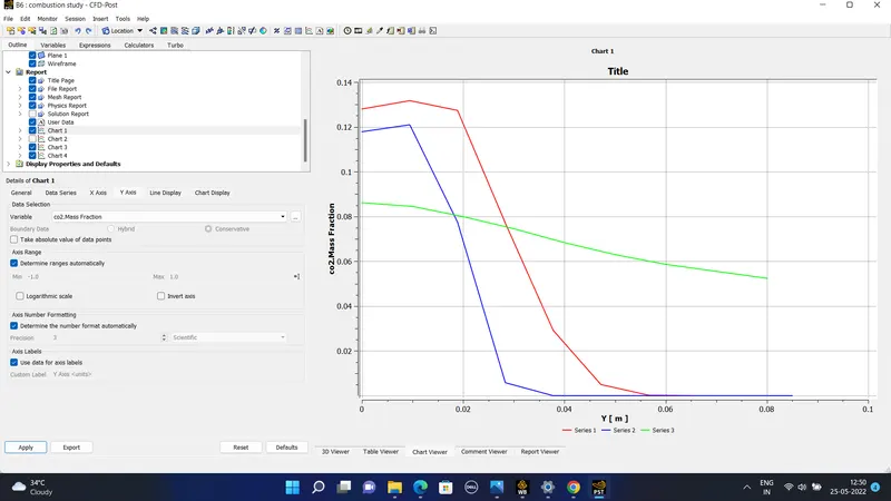
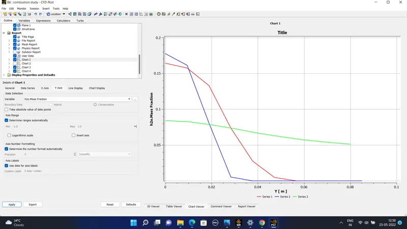
Now we are using the 5% of water and the rest 95% contains the fuel that is methane. The iteration was again carriede out for 1500 iterations so this would lead to the following results-
#) For the case of 15% water and the 85% methane fuel the results obtained are-
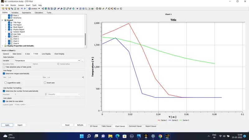
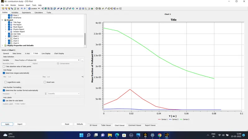
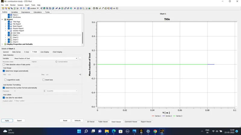
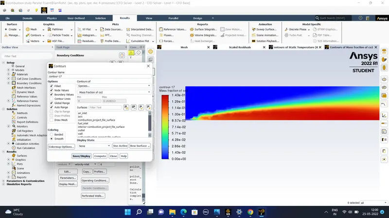
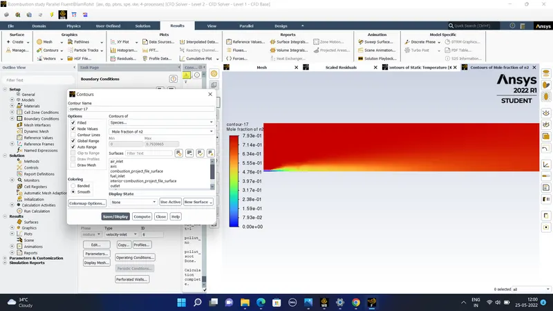
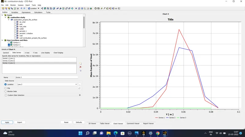
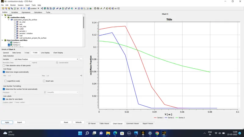
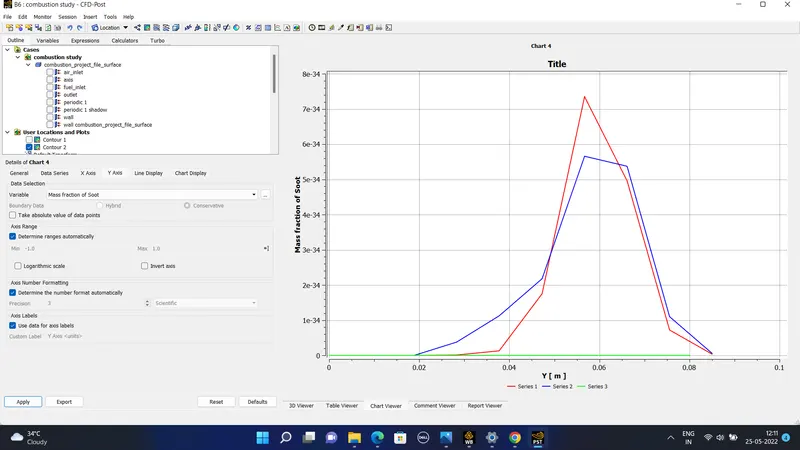
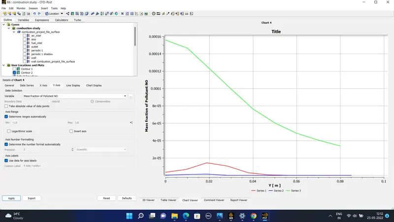
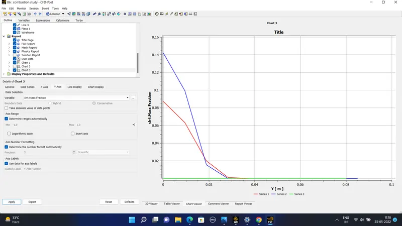
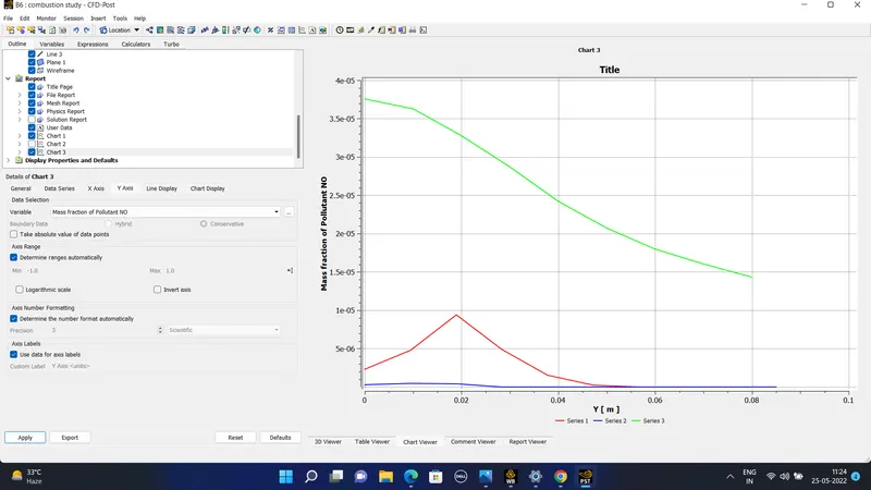
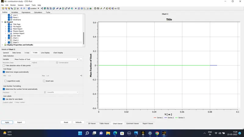
The plots of the mass fraction and the NOx and the soot is -
#) For the 30% of water and the fuel of the 70% methane the following data is obtained-
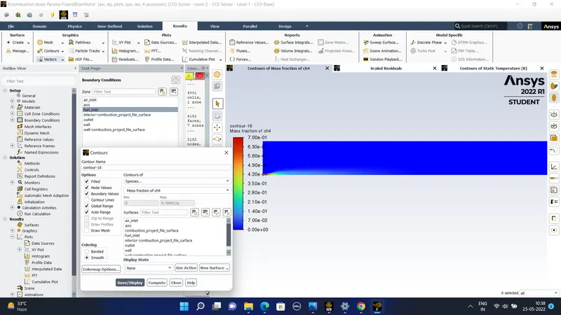
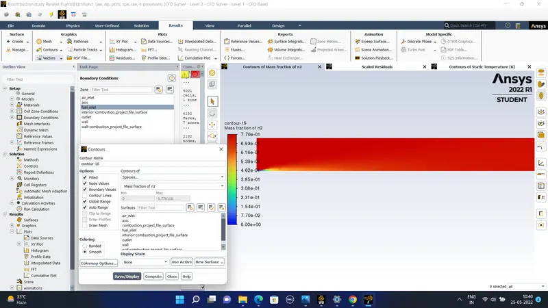
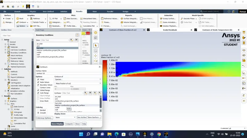
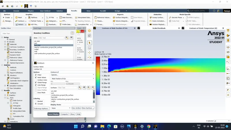
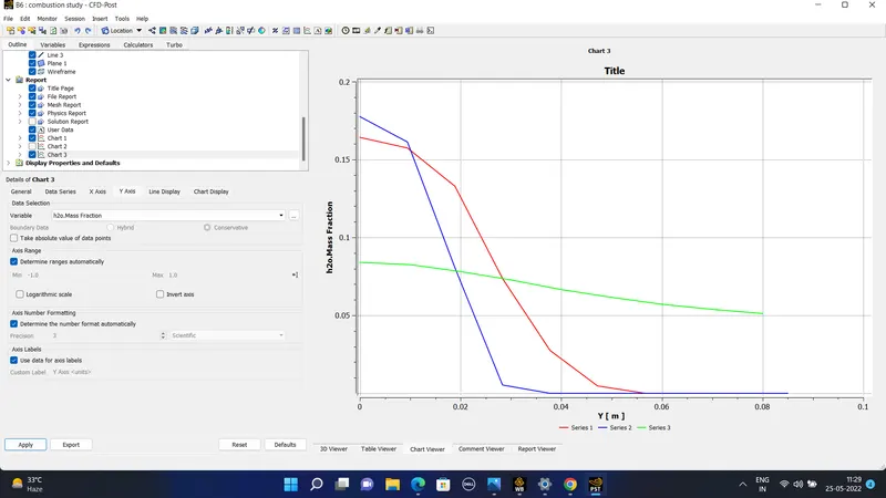
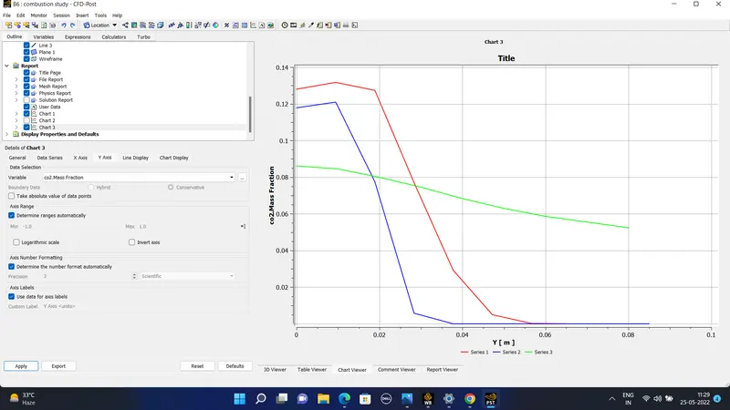
The plots of the mass fraction along the perpendicular length of the line is -
#) Conclusions obtained after giving and varying the water percentage in methane fuel-
1)In the baseline mesh setup in which the whole amount of CH4 is present for as fuel the amount of soot and NOx is greater compared to other cases. the maximum temperature reached is about 2300K.
2) In the next case 2 when water is added with fuel from 5% to 30% as the water percentage is increased we see a reduction in the amount of the NOx production. As more percentage of water is added we get less amount of Nox productions.
3) Similar to the NOx in the exhaust we can observe that the mass fraction of CO2 is also decreasing as water percentage is increasing the mass fraction of N2 is almost constant as the percentage is increased which means the flame instability is constant for all cases of combustion.
4) In the case of soot it is the mass fraction of the soot for the cases 1 to 2 so after increasing the water percentage we can see that the soot formation has reduced. In case 3 and case 4 it is seen that the soot formation is more towards the end of the burner which is a common practice for the burners.
5) From the whole simulation it is concluded that adding w2ater to the fuel will reduce the amount of NOx formation and the soot formation.