Week 10 - Simulating Combustion of Natural Gas.
1.Aim:
- To perform a combustion simulation on the combustor model usig methane as fuel.
2.Theory:
- Combustion refers to the process where a substance burns in the presence of Oxygen, giving off heat and light in the process. You might have heard that certain substances are combustible whereas some are non-combustible.
-
Combustion is a chemical process or a reaction between Fuel (Hydrocarbon) and Oxygen. When fuel and oxygen react it releases the heat and light energy. Heat and light energy then result in the flame. So, the formula for Combustion reaction is Hydrobcarbon + Oxygen = Heat energy.
-
The combustion reaction happens as the fuel and oxygen react, creating fire or heat and light. Combustion happens as the gasoline, most commonly a fossil fuel, reacts with the oxygen in the air to create heat. The heat produced by the combustion of fossil fuels is used in the operation of machinery such as boilers, furnaces, ovens and engines.
- Rapid combustion is a form of combustion, otherwise known as a fire, in which large amounts of heat and light energy are released, which often results in a flame. This is used in a form of machinery such as internal combustion engines and in thermobaric weapons. Such a combustion is frequently called an explosion.
- Combustion of an organic fuel in air is always exotherimc because the double bond in O2 is much weaker than other double bands or pairs of single bonds, and therefore the formation of the stronger bonds in the combustion products CO2 and H2O results in the release of energy.
2.1 Stoichiometric combustion of a Methane
- The most common oxidizer is air. The chemical equation for stoichiometric combustion of methane - CH4 - with air can be expressed as
CH4 + 2(O2 + 3.76 N2) -> CO2 + 2 H2O + 7.52 N2
- If more air is supplied some of the air will not be involved in the reaction. The additional air is termed excess air, but the term theoretical air may also be used. 200% theoretical air is 100% excess air.
- The chemical equation for methane burned with 25% excess air can be expressed as
CH4 + 1.25 x 2(O2 + 3.76 N2) -> CO2 + 2 H2O + 0.5 O2 + 9.4 N2
2.2 Chemical Kinetics
-
Chemical kinetics, also known as reaction kinetics, is the branch of physical chemistry that is concerned with understanding the rates of chemical reactions. It is to be contrasted with thermodynamics, which deals with the direction in which a process occurs but in itself tells nothing about its rate.
- Chemical kinetics includes investigations of how experimental conditions influence the speed of a chemical reaction and yield information about the reaction mechanism's and transient state, as well as the construction of mathematical models that also can describe the characteristics of a chemical reaction.
2.3 Chemical reaction model:
- Chemical reaction models transform physical knowledge into a mathematical formulation that can be utilized in computational simulation of practical problems in chemical engineering. Computer simulation provides the flexibility to study chemical processes under a wide range of conditions.
- Chemical reaction can be classified as: A reaction in which two or more reactant combine to form a single product is known as combination reaction. Combination reaction is also known as synthesis reaction. A reaction in which a single compound breaks into two or more simpler compounds is known as decomposition reaction.
2.4 Factor affecting reaction rate:
- Nature of reactants
- Physical state
- Surface area of solid-state
- Concentration
- Temperature
- Catalysts
- Pressure
- Absorption of light
2.5 Application
- Humans have been making practical use of combustion for millennia. Cooking food and heating homes have long been two major applications of the combustion reaction. With the development of the steam engine by Denis Papin, Thomas Savery, Thomas Newcomen, and others at the beginning of the eighteenth century, however, a new use for combustion was found: performing work. Those first engines employed the combustion of some material, usually coal, to produce heat that was used to boil water. The steam produced was then able to move pistons and drive machinery. That concept is essentially the same one used today to operate fossil-fueled electrical power plants.
2.6 Mass fraction
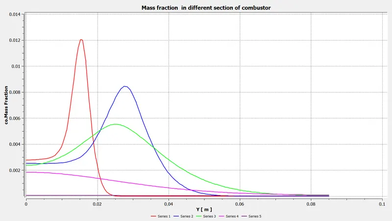
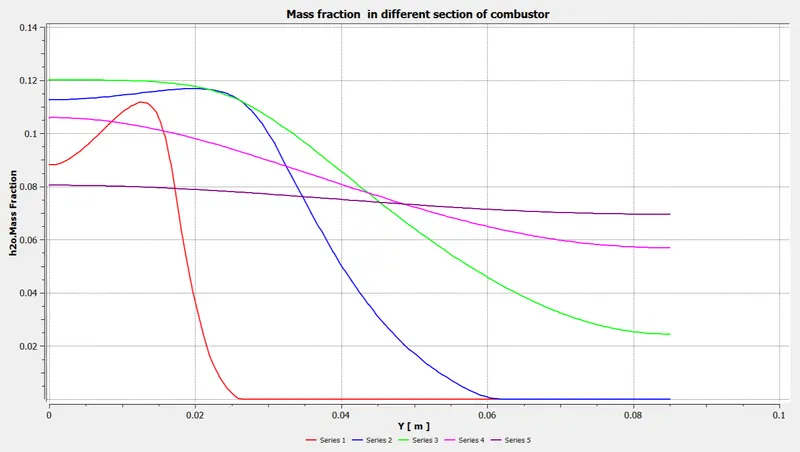
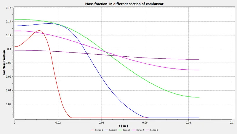
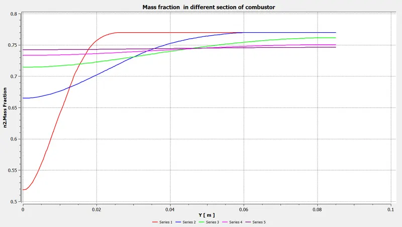
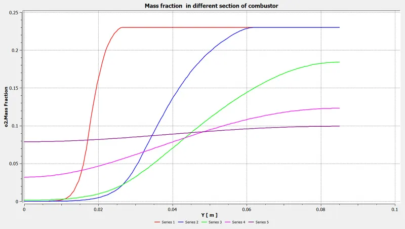
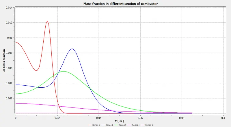
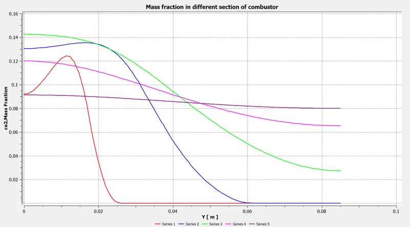
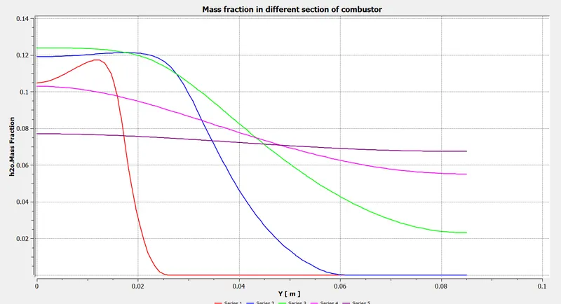
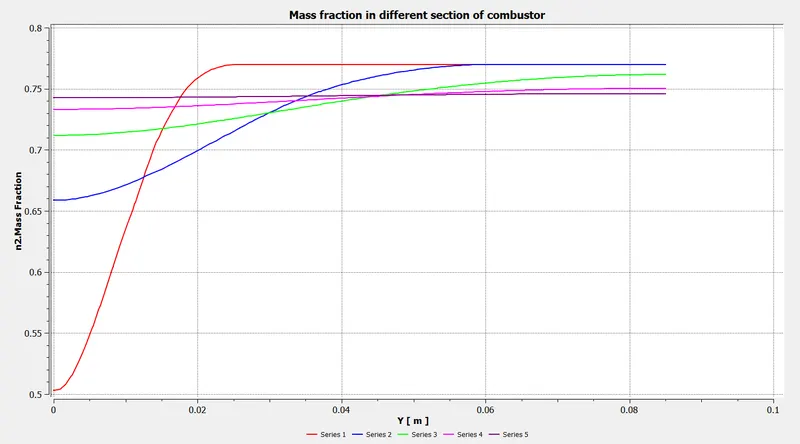
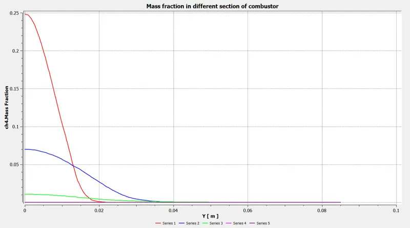
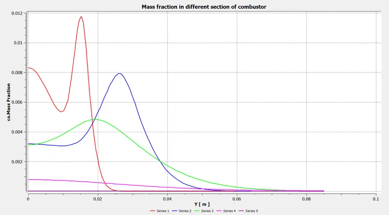
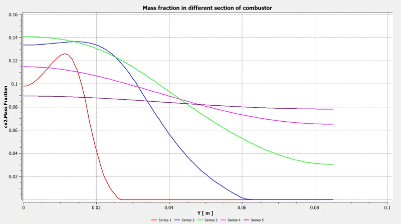
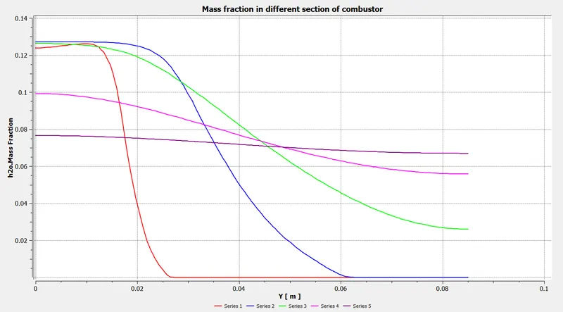
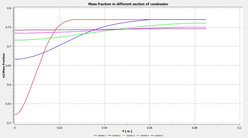
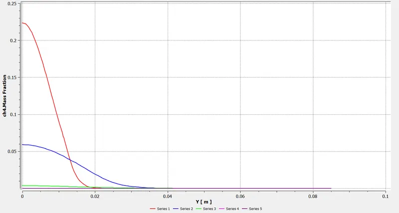
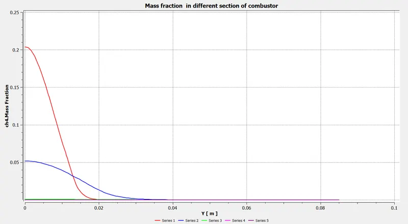
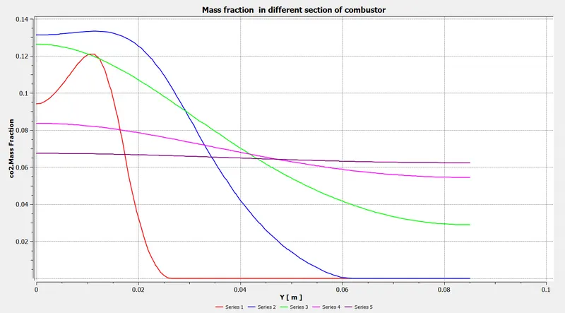
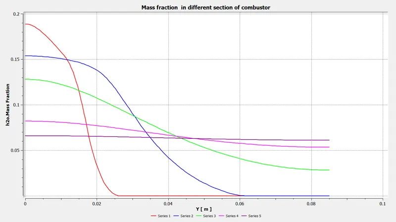
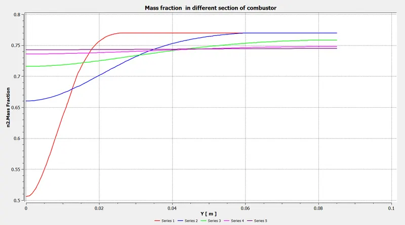
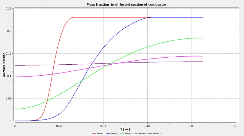
- The mass fraction is the ratio of the mass of a component in the mixture to the total mass of the mixture. For a solution, it is the ratio of the mass of a solute to the mass of the solution. The sum of the mass fraction of each component is always equal to one. It is an intensive property.
2.7 Nitrogen oxide (NOx) emissions:
-
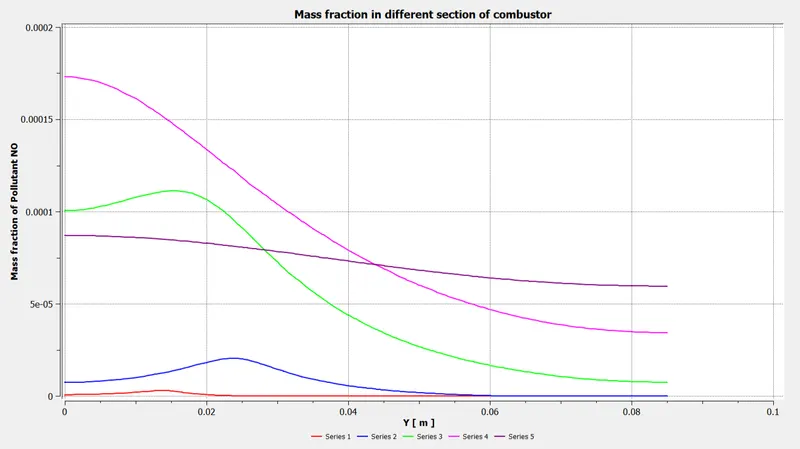
Nitrogen oxides emissions from the fuel bound nitrogen during biomass combustion. Average emission factors in the range of 63–72 mg/MJ for woody biomass combustion. Hard times for market introduction of nitrogen-rich alternative solid biofuels. Research need on residential-scale technologies for nitrogen oxides abatement.
2.8 Soot Formation
-
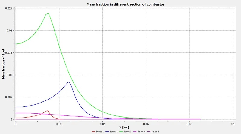
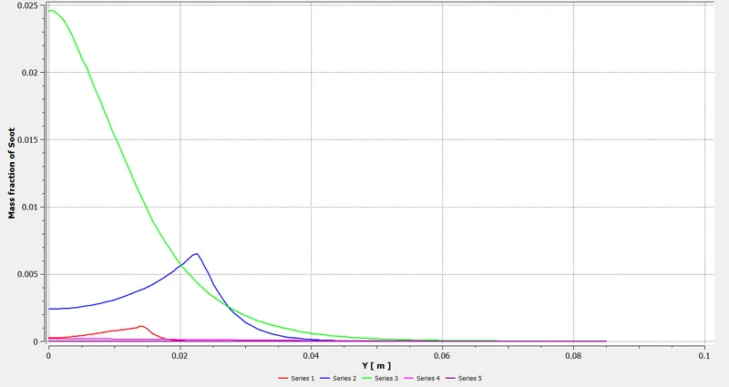
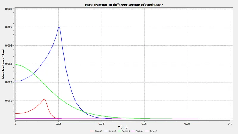
Soot forms as a result of incomplete combustion. To achieve incomplete combustion instead of complete combustion, the fuel must burn at a lower temperature with a slightly reduced supply of oxygen. When the fuel burns, it breaks into small particles that include soot, which settles out as a dark powdery deposit.
2.9 Steps involves in Ansys Fluent software:
- Geometry: Construct a two or three dimensional representation of the object to be modelled and tested using the work plane co-ordinate system within Ansys.
- Mesh: At this point understands the makeup of the part. Now define how the modelled system should be broken down into finite pieces.
- Setup: This case setup will be done using Ansys Fluent.
- Solution: Ansys Fluent where run time result visualization is done.
- Results: Post processing of results will be done using CFD post.
3.Procdure:
3.1 Geomentry
1.Open new project, by clicking on Fluid flow(Fluent) in Ansys workbench.
2.Now click on geometry to import Gate valve. It will redirect to Spaceclaim, Ansys geometry model.
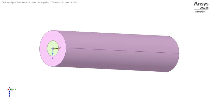
Fig: Cylinder Geometry
3. It is a 3D model and we are only interested in the 2D geometry of the combustor.Therefore, we need to split the body 3/4th and select the plane XY plane region of geometry since we are using the axisymmetric condition.
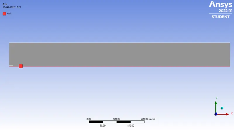
Fig: Geometry
4.Exit from Spaceclaim and click on mesh to open mesh menu.
3.2 Mesh
5.Select wall face and press right click of mouse, it will open a menu. Click on option create named selection and write suitable name for Inlet and outlet faces.
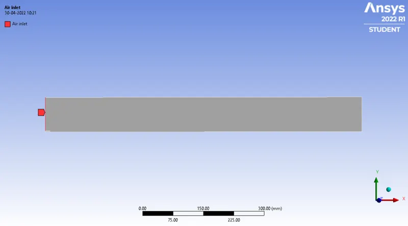
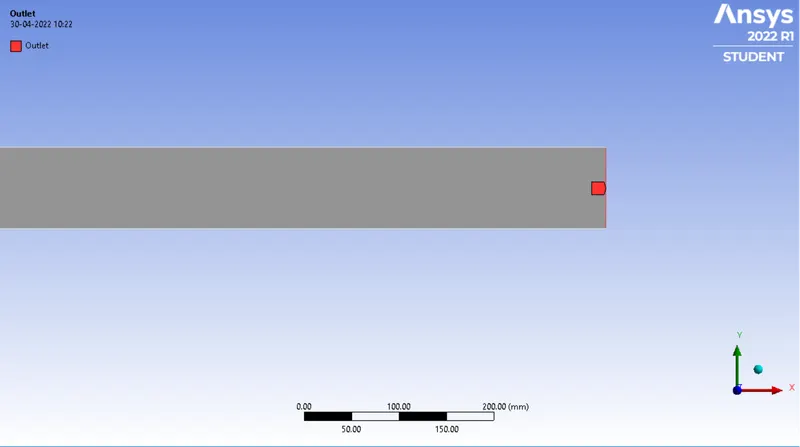
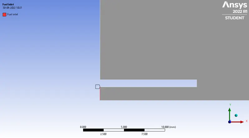
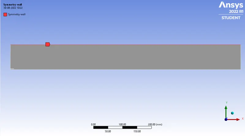
Fig: Selection of name
6. Now click on mesh option and choose generate mesh. It will generate mesh.
- Mesh Element sizing= 1 mm
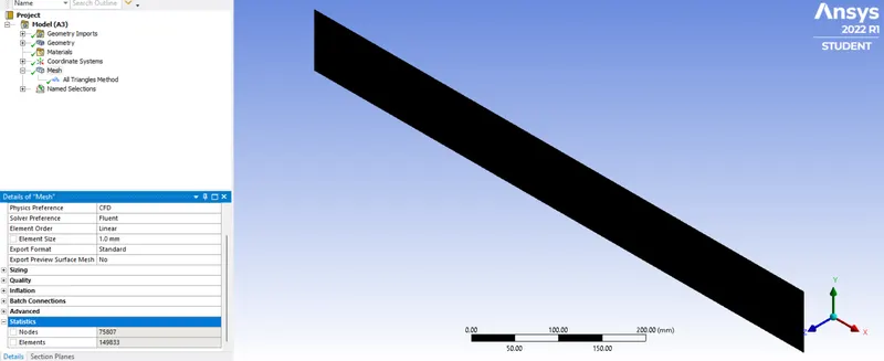
Fig:Generated Mesh
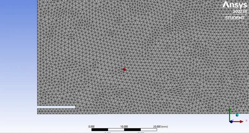
Fig: Futhur zooming of Mesh
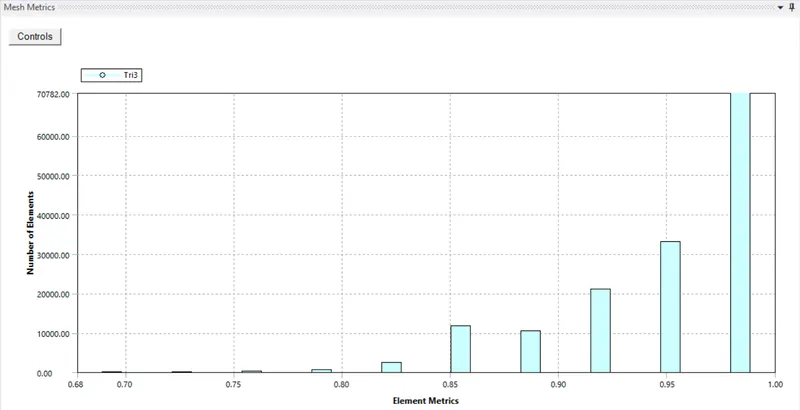
Fig: Mesh quality
3.3 Setup and Solution
7.Exit mesh and open setup. First, Check mesh, it is throwing no error then only we can proceed further. We are going to do pressure based steady state simulation.
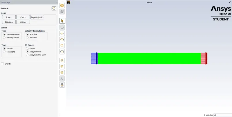
8. Go to physics menu and select viscous model. It will open a menu, choose realizable K-epsilon model close it.
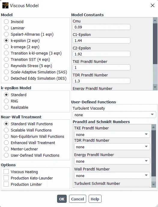
Fig: Viscous model parameters
9. Click on species model and move instalization add Methane 2 steps.
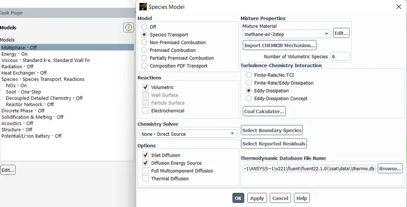
Fig: Species model
10.Click on material and choose Air and Methane as working fluid. check working fluid by clicking on cell zone conditions option, if it Fluid is Air and Methane then proceed.
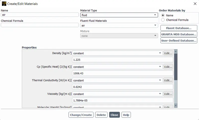
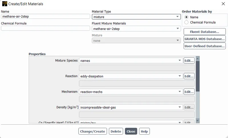
Fig: Material selection
11.Now go to boundaries option to set boundary conditions. Select inlet x and click on option edit. It will open a menu, Where it is thermal radiation, momentum etc. Give the required value.
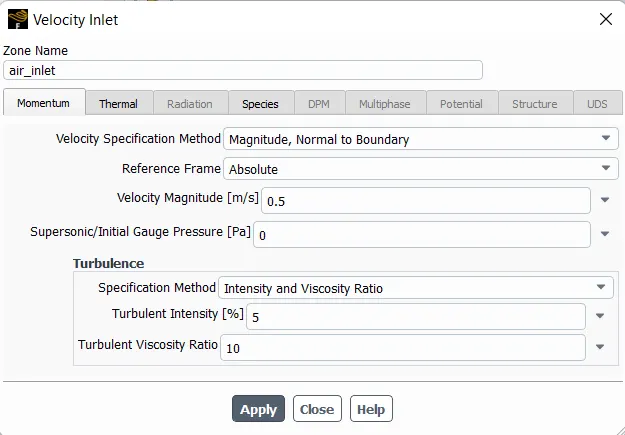
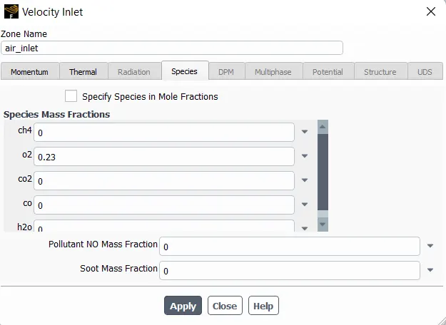
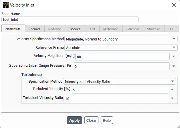
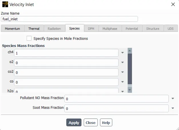
Fig: Boundary conditions
12.Now click on Hybird intialization for calculate approximate values of velocity and pressure.
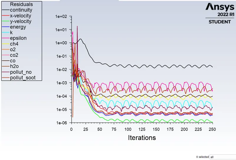
13.Change the number of iteration 250(approx) and click on calculate.
14.Exit setup and double click on result to open CFD post. Check boxes to see walls and other parts.
4.Results
Case:1
- Methane = 100%
- H2O = 0%
Residual
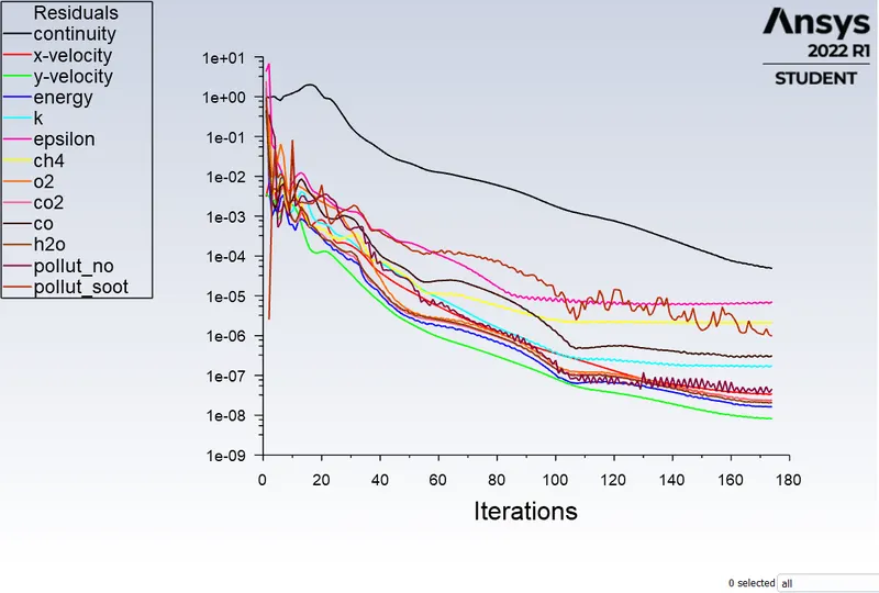
Temperature plot
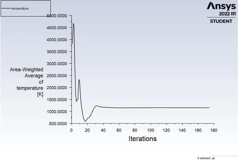
Temperature and Mass Fraction contours
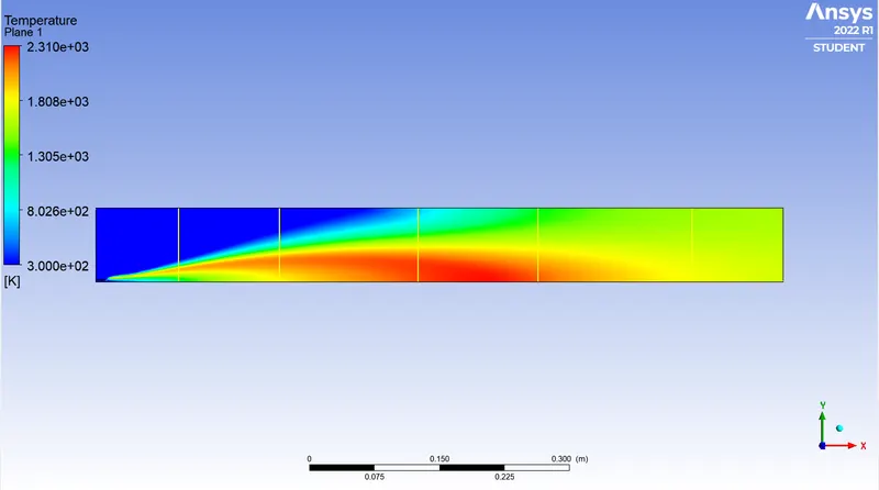
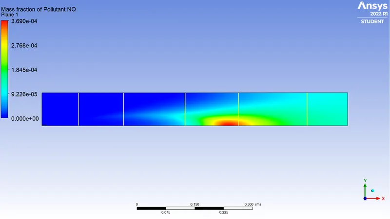
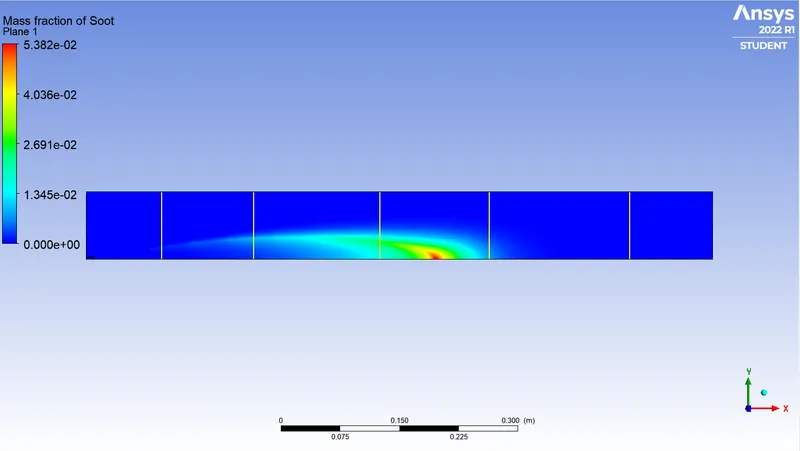
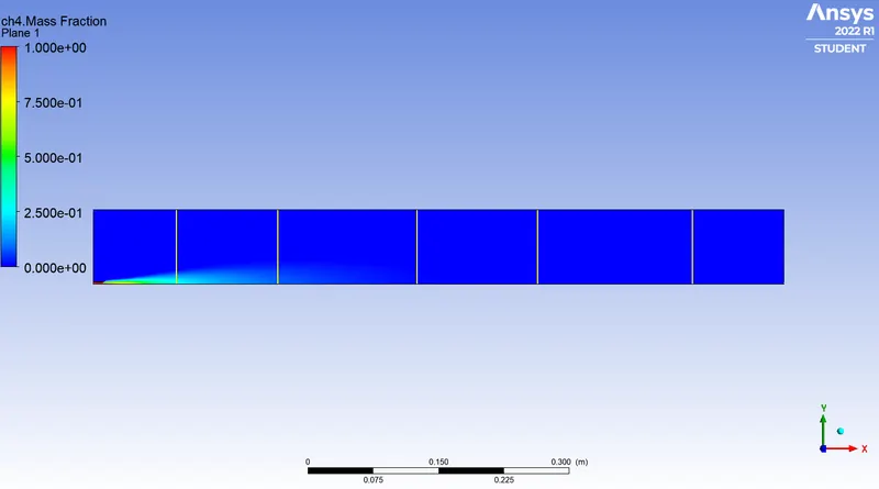
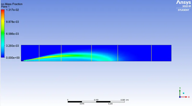
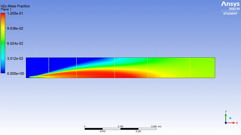
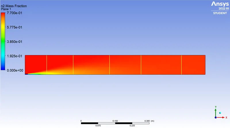
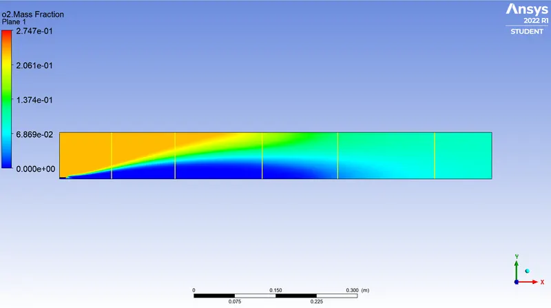
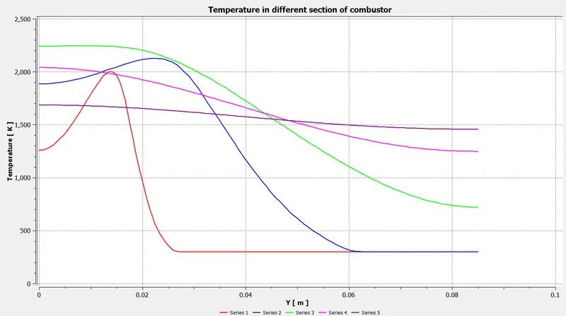
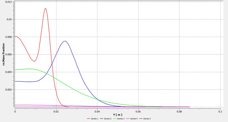
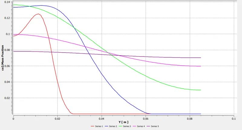
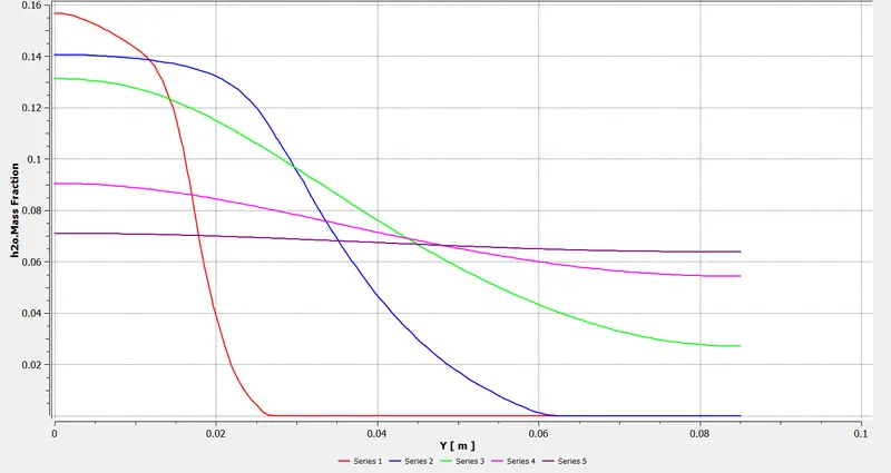
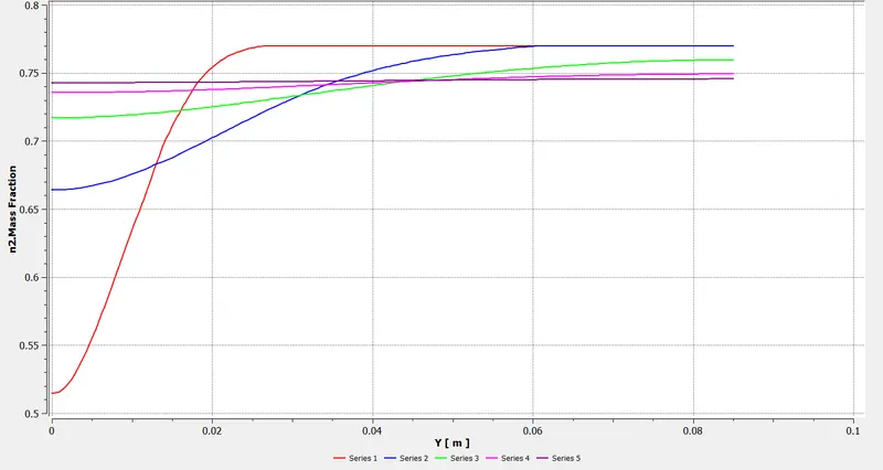
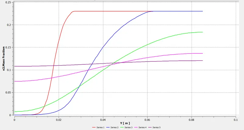
Temperature and Mass fraction charts
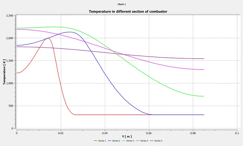
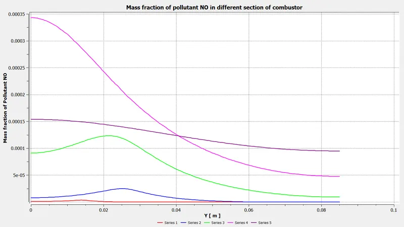
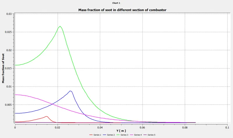
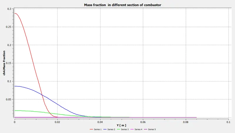
Case:2
- Methane = 95%
- H2O = 5%
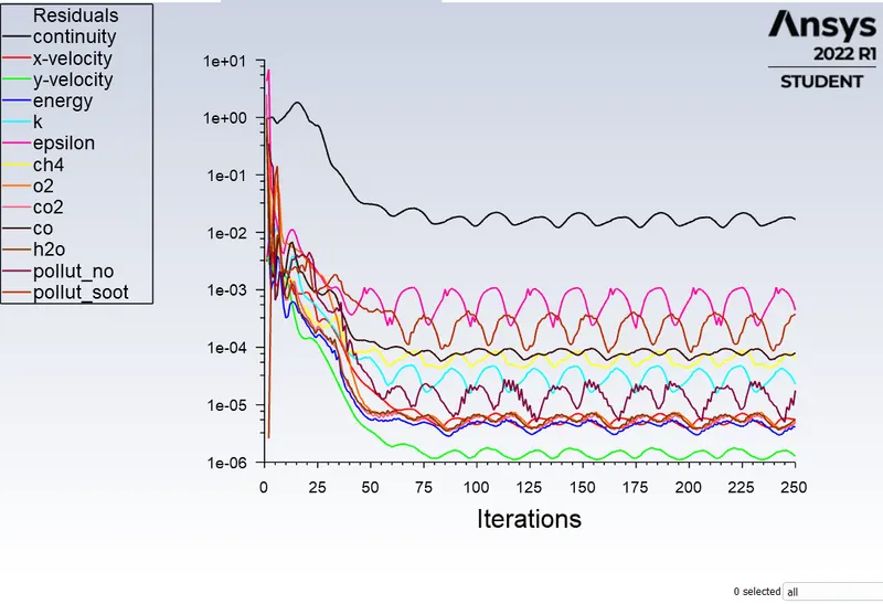
Residual
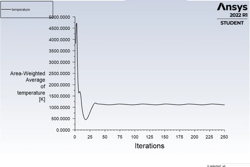
Temperature plot
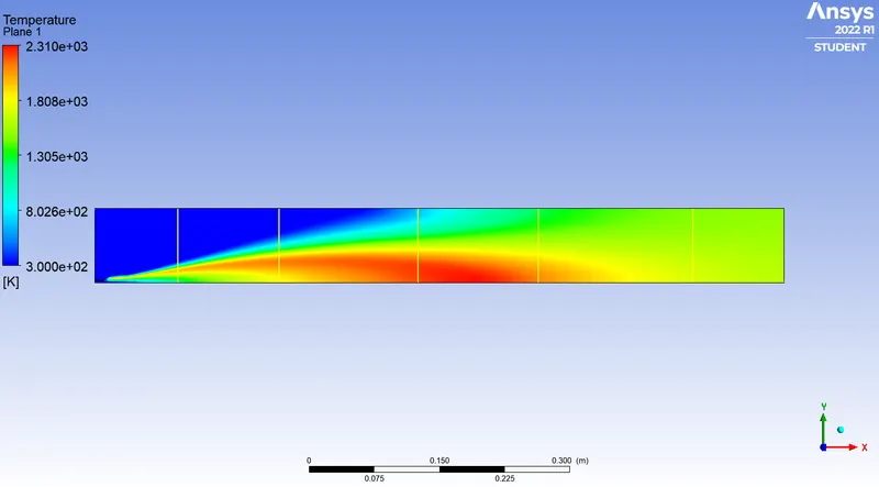
Temperature and Mass Fraction contours
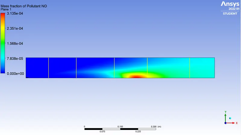
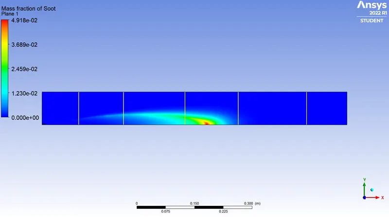
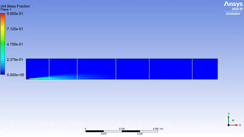
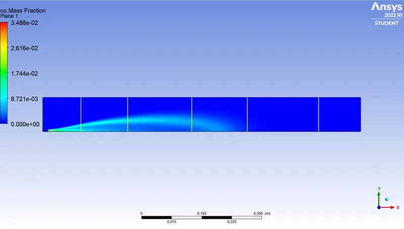
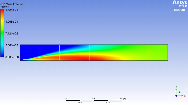
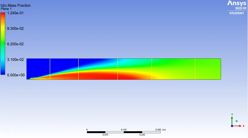
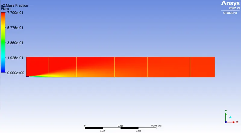
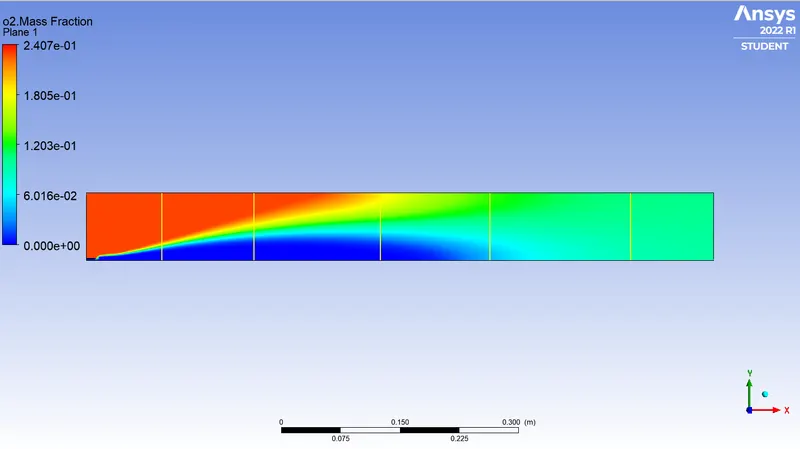
Temperature and Mass Fraction Charts
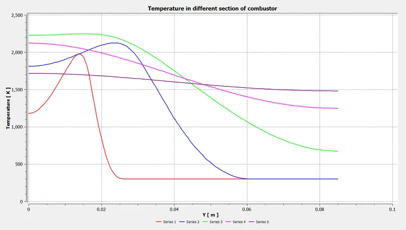
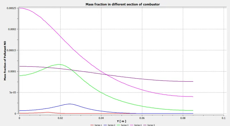
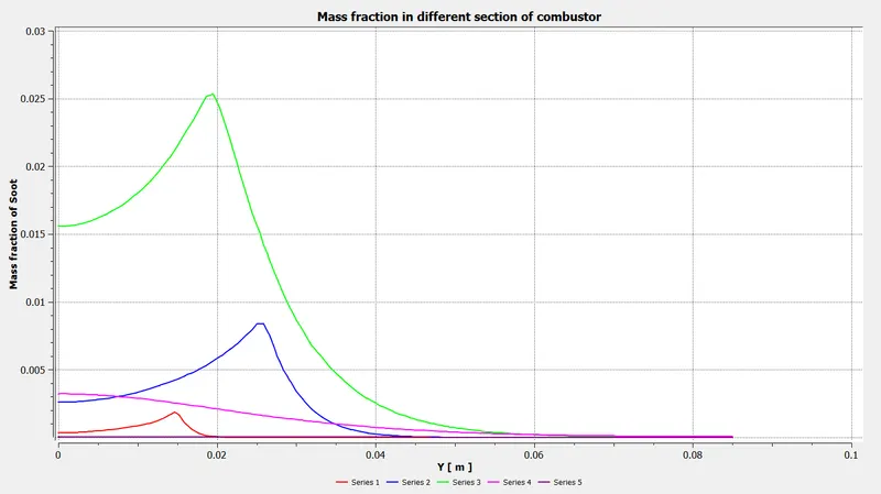
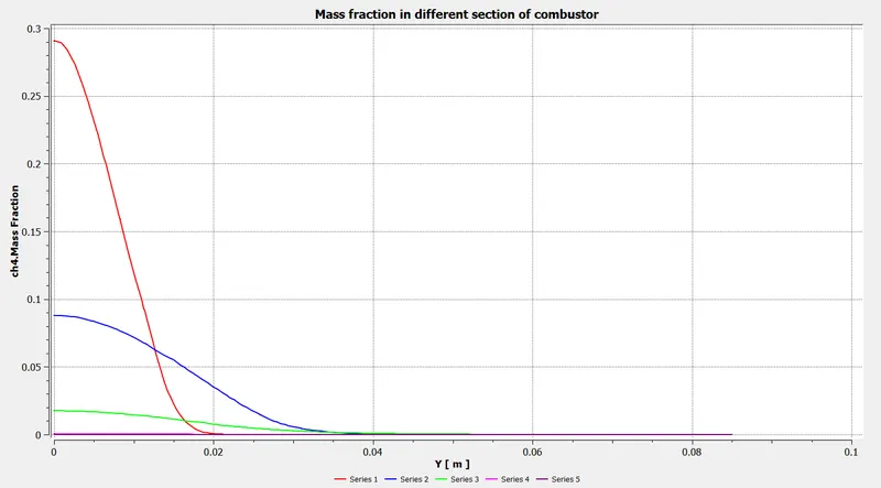
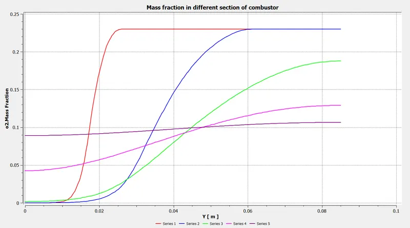
Case:2
- Methane = 90%
- H2O = 10%
Residual
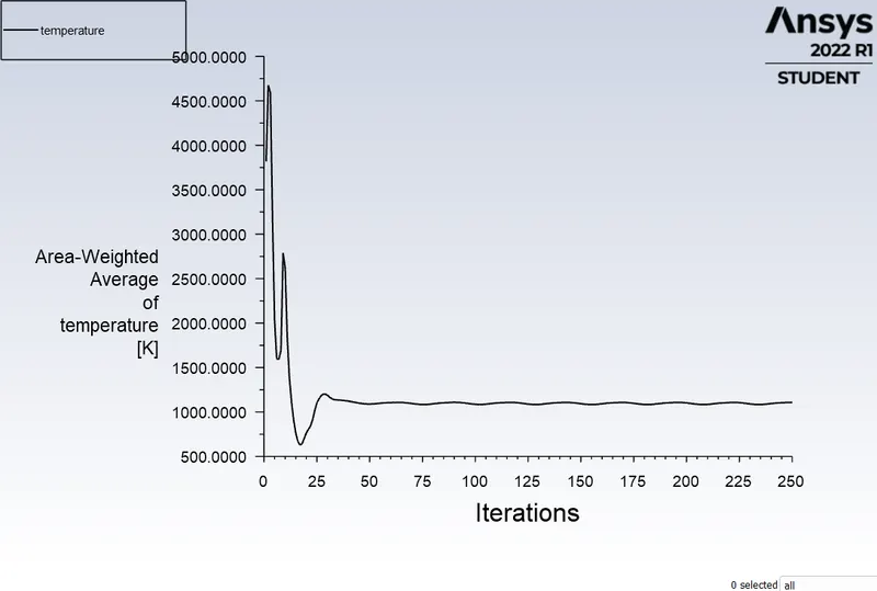
Temperature plot
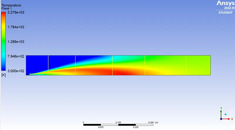
Temperature and Mass Fraction contours
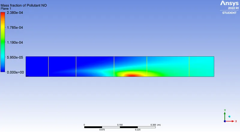
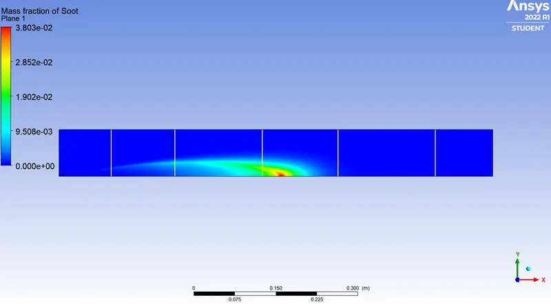
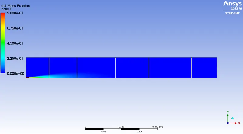
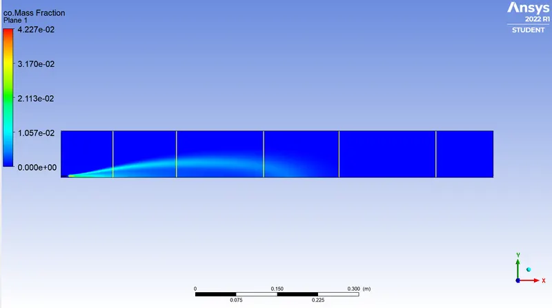
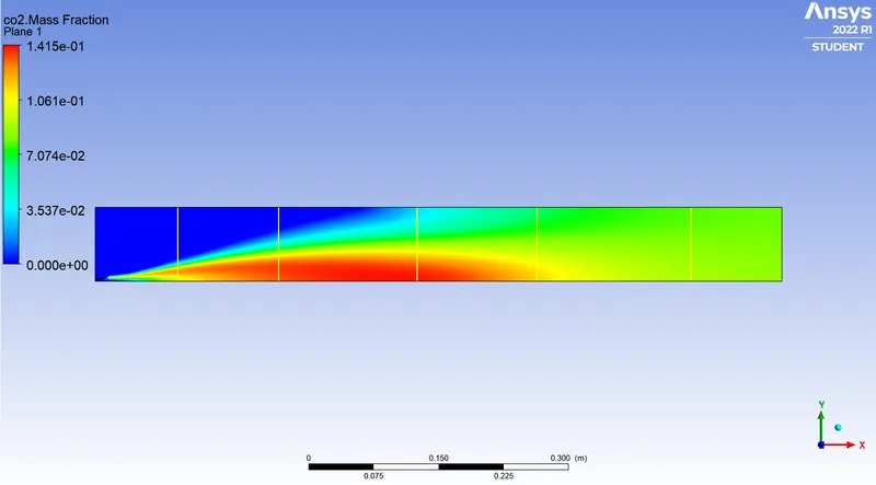
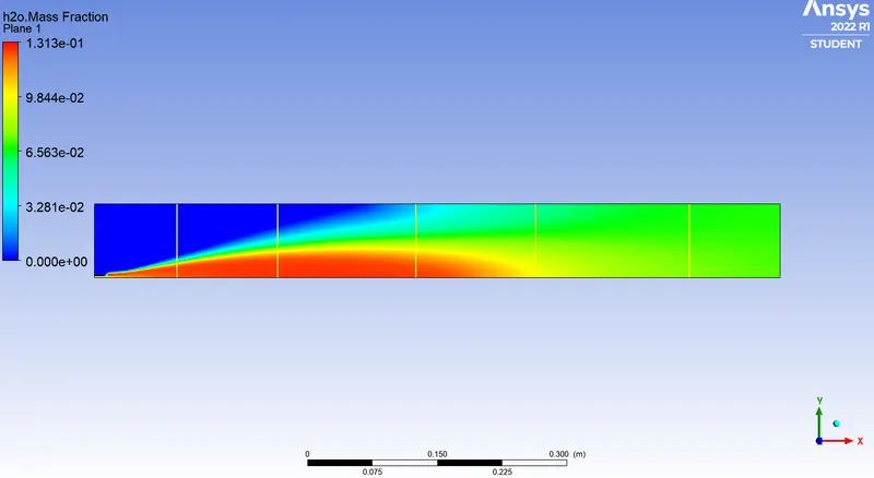
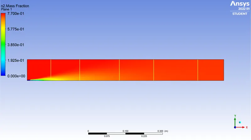
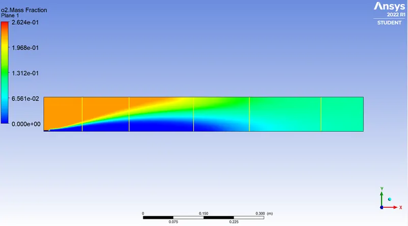
Temperature and Mass Fraction Charts
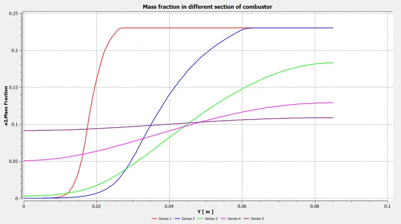
Case:3
- Methane = 80%
- H2O = 20%
Residual
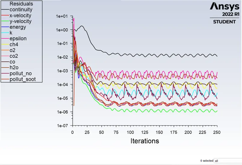
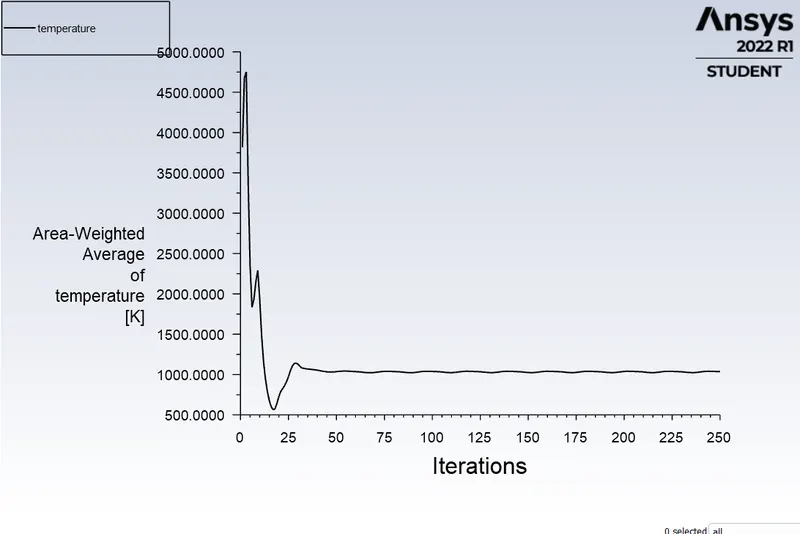
Temperature plot
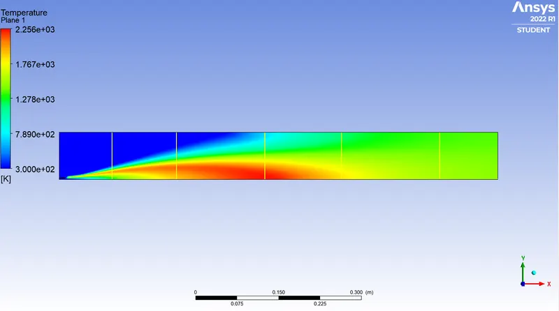
Temperature and Mass Fraction contours
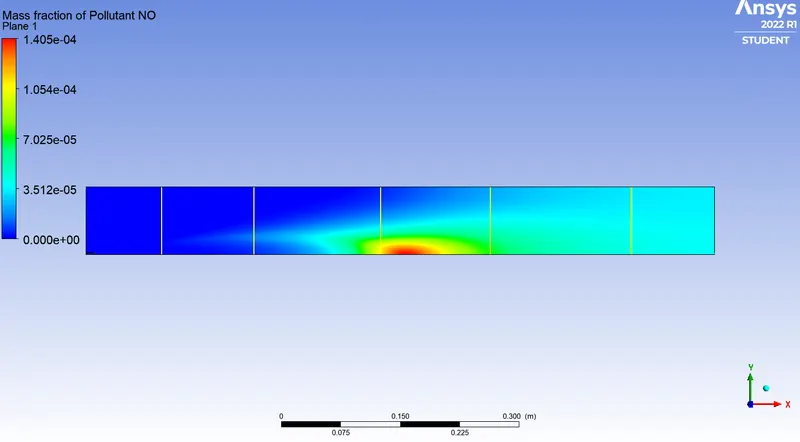
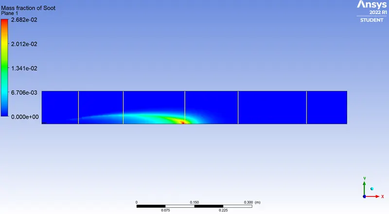
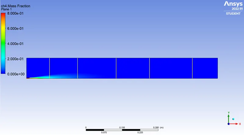
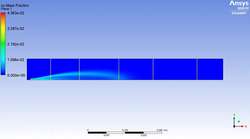
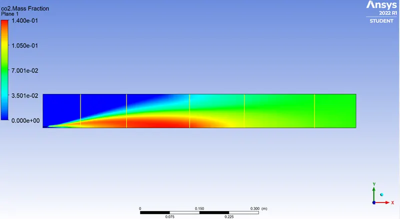
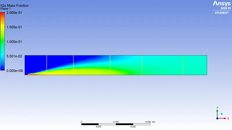
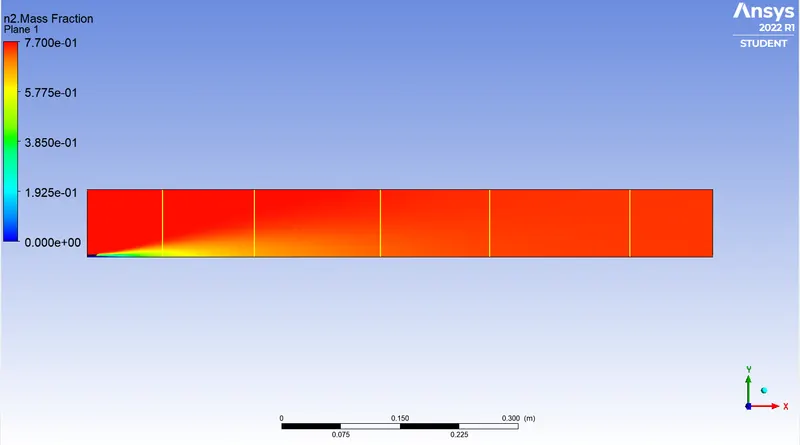

Temperature and Mass Fraction Charts
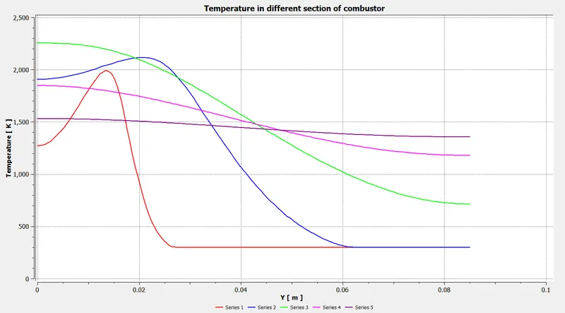

Case:3
- Methane = 70%
- H2O = 30%
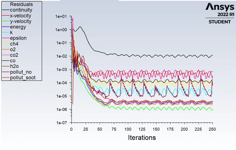
Residual
Temperature plot
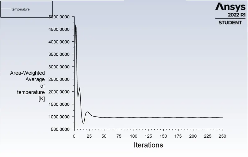
Temperature and Mass Fraction contours
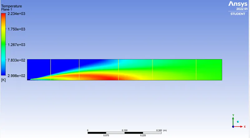
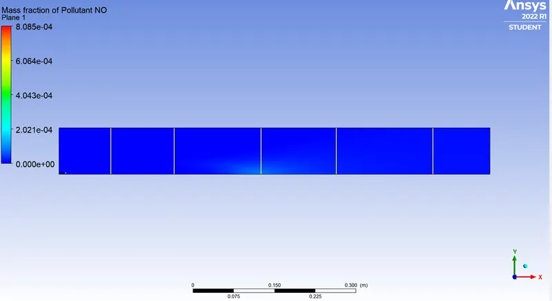
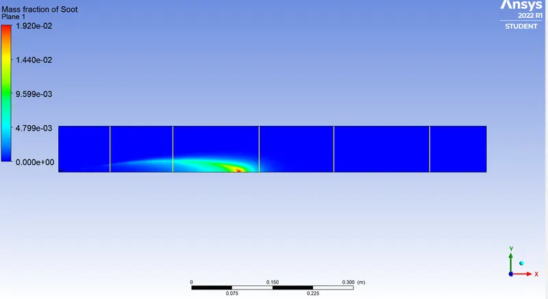
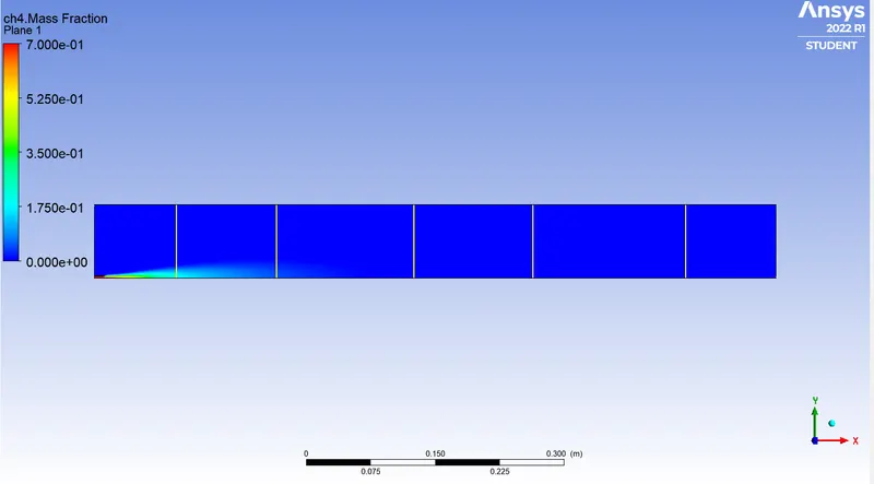
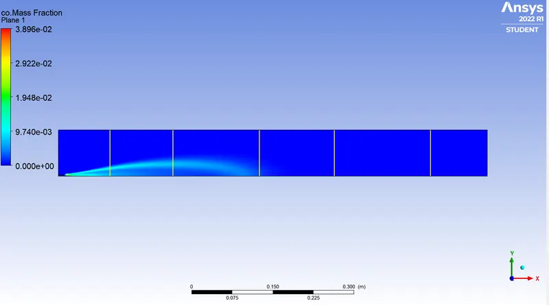
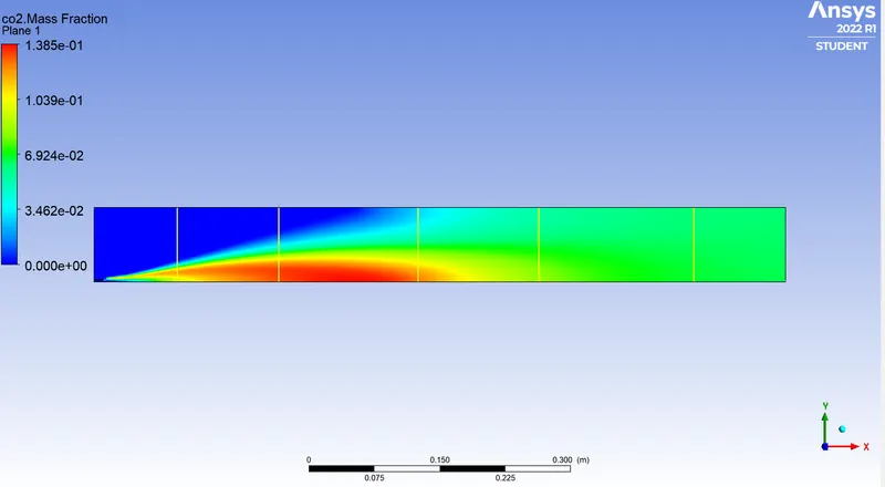
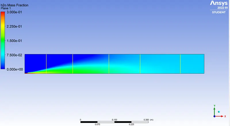
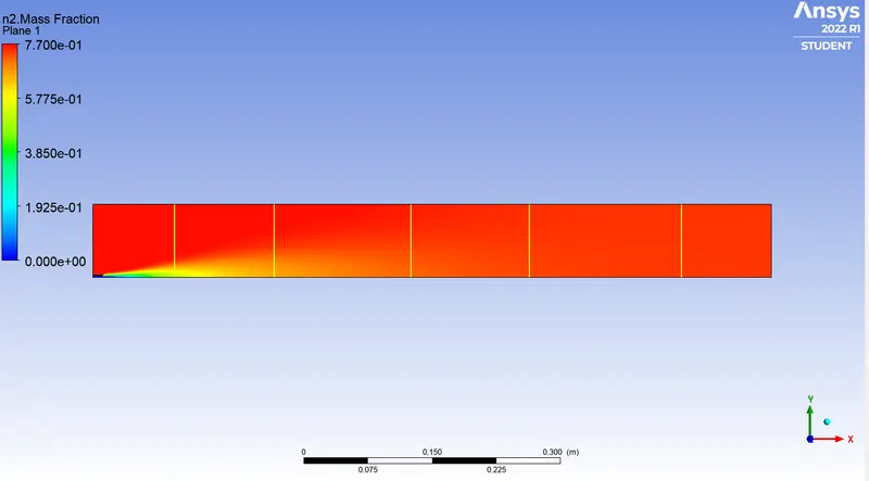
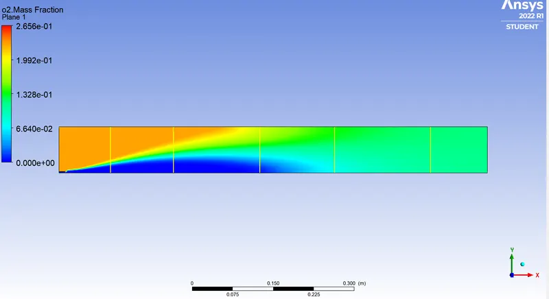
Temperature and Mass Fraction Chart
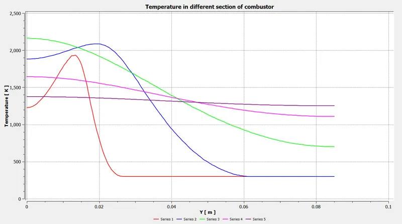
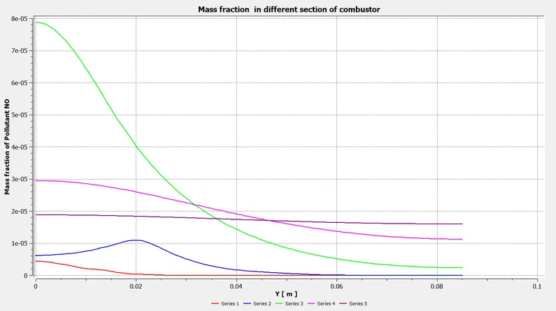

5.Conclusion:
- NOx emissions and soot formations reduced as there is an increase in the addition of water.
- But the efficiency of combustion reduces as there is reduction incomplete combustion.