Week 10 - Simulating Combustion of Natural Gas.
Aim
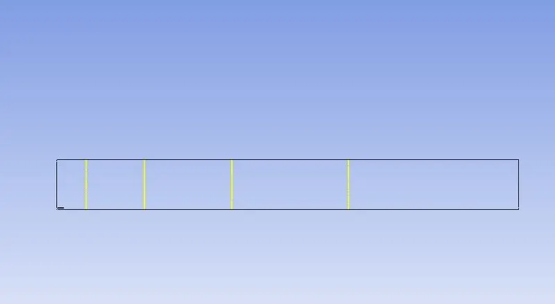
Perform a combustion simulation on the combustor model and plot the variation of the mass fraction of the different species in the simulation using line probes at different locations of the combustor.
Objectives
- Part 1: Plot for CO2, H2O, CH4, N2, O2, NOx emissions & Soot formation at different locations of the combustor
- Part 2: Add the water content in the fuel from 5% to 30% by mole and observe the effect of it on the results. Provide line plots and contours to prove your claim.
Methodology
Combustion is a chemical process or reaction between fuel and oxygen to form heat and other products. The fuel is a hydrocarbon. It can be seen in automobiles, aircraft, and other machinery.
As a result of combustion lot of bi-products are formed. In order to study this combustion and the resulting species, the species model in Ansys fluent is used and eddy dissipation is used to burn the fuel.
Eddy dissipation is more effective in the k-epsilon turbulence model, Hence k-epsilon turbulence model is selected for this simulation.
- Pre-processing
Model creation
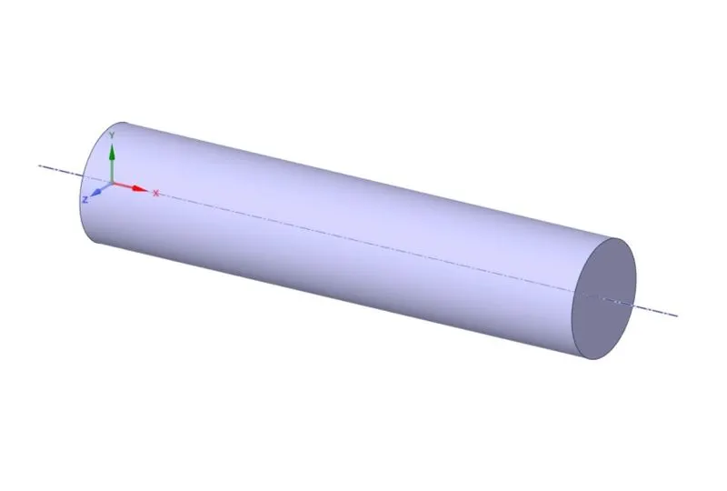
A cylindrical combustor model is selected to perform this combustion simulation. Since the model is axisymmetric a 2D section is extracted to simplify the computational efforts. Since it is an axisymmetric simulation, the geometry should be on the XY plane and the axis should be on X-axis.
The model is imported into ANSYS SpaceClaim and the 2D geometry is extracted from it using the split body feature.

Meshing
In order to identify all regions, the geometry is named below.
- Inlet_air
- Inlet_fuel
- Axis
- Outlet
- Wall
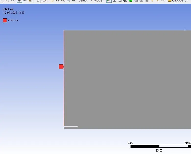
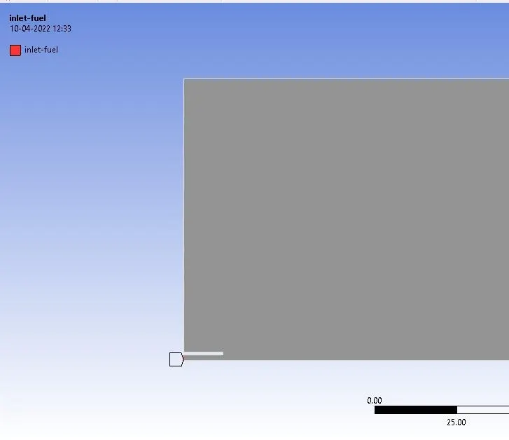
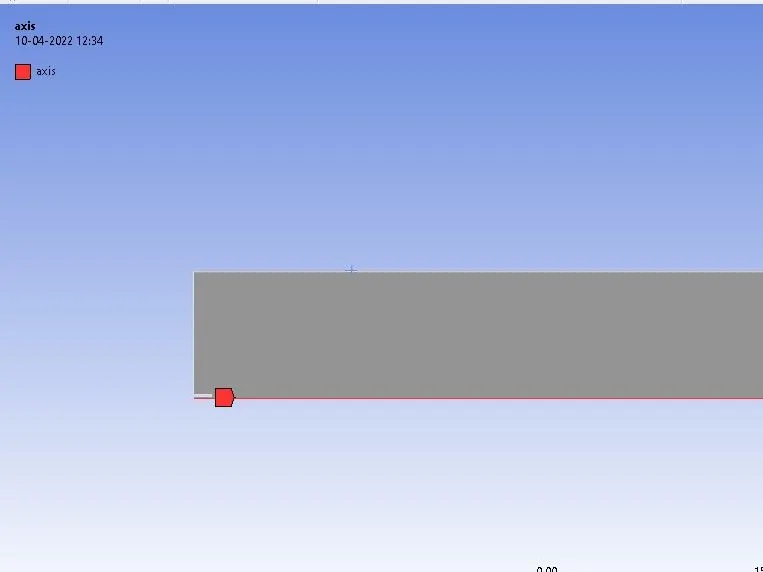
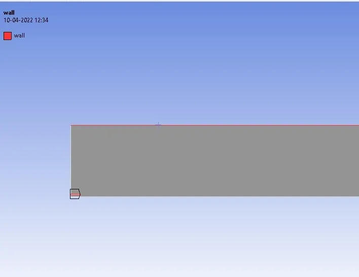
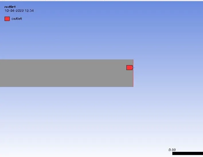
We will be doing a standard meshing with element size = 2mm.
Capture proximity is turned on. Number of cells across gap = 3
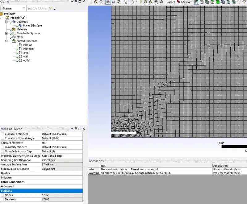
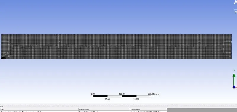
Number of elements = 17183
Setting up the problem
Here we set up the problem by applying relevant
- Initial conditions
- Boundary conditions
- Material properties
- Turbulence Models
We will be doing a steady-state pressure-based axisymmetric analysis.
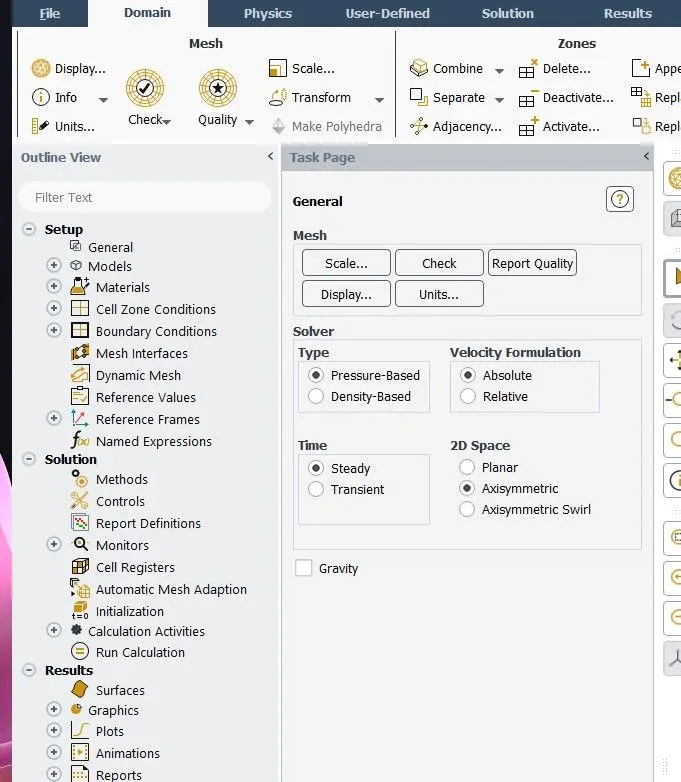
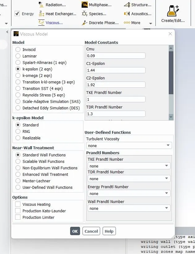
Since the combustion involves the burning of different species, energy and species are turned on.
K-epsilon is taken as a turbulence model as the overall reaction rate is controlled by turbulent mixing.
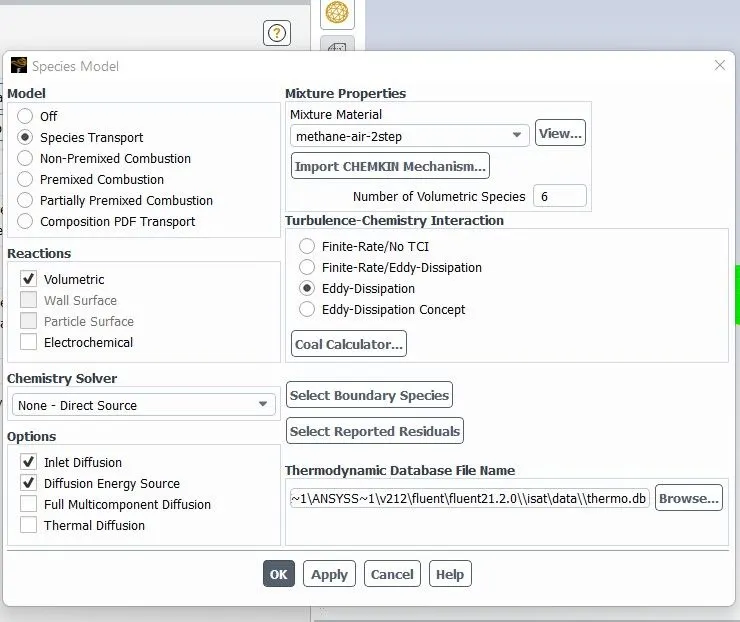
The species feature is turned on to input the mass fractions of different species present in the fuel. From the species tab, reaction type is selected as volumetric. In options enable inlet diffusion and diffusion energy source. Mixture material taken as methane-air-2step and eddy dissipation is selected as the turbulence chemistry. Click on ok,
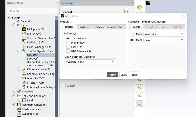
To predict the formation of pollutant NO, the NOx model is turned on. To visualize the formation of soot, soot is also enabled.
Give o2 as an oxidant.
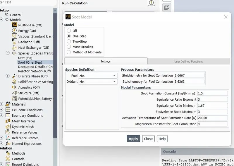
Next step is to give the boundary conditions. Following changes are made
Inlet_air: Velocity inlet
Velocity magnitude = 0.5 m/s
Species: O2 = 0.23 (air contains 0.23 mass fraction oxygen)
Inlet_fuel: Velocity inlet
Velocity magnitude = 80 m/s
Species: CH4 = 1 (Fuel contain 1 mole CH4)
H2O = 0
Parameters are created here to simplify the calculation process. CH4 and H2O are defined as input parameters.
Outlet: Pressure outlet
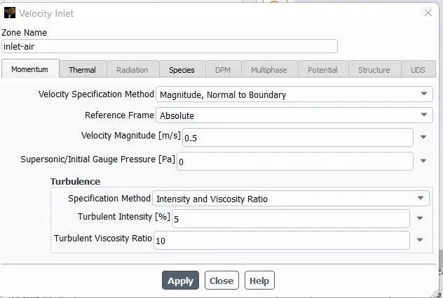
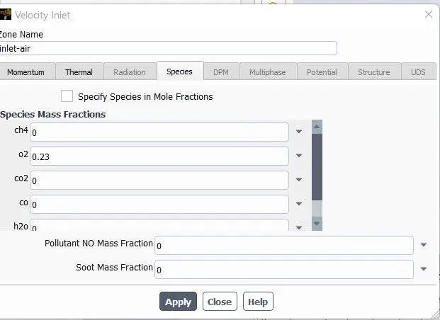
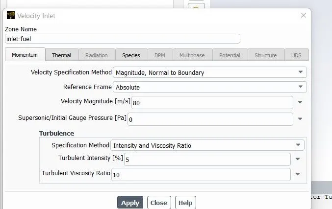
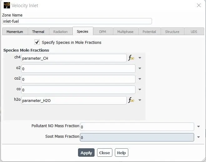
After setting up the boundary conditions, the solution has been initiated using hybrid initialization. A temperature plot has been created at the outlet to observe the convergence. The problem is run for 750 iterations.

The problem is ran for 4 different cases based on the water addition,
|
H2O Fraction |
CH4 Fraction |
|
|
Case 1 |
0 (0%) |
1 |
|
Case 2 |
0.1 (10%) |
0.9 |
|
Case 3 |
0.2 (20%) |
0.8 |
|
Case 4 |
0.3 (30%) |
0.7 |
- Solutions
Part 1 (case 1)
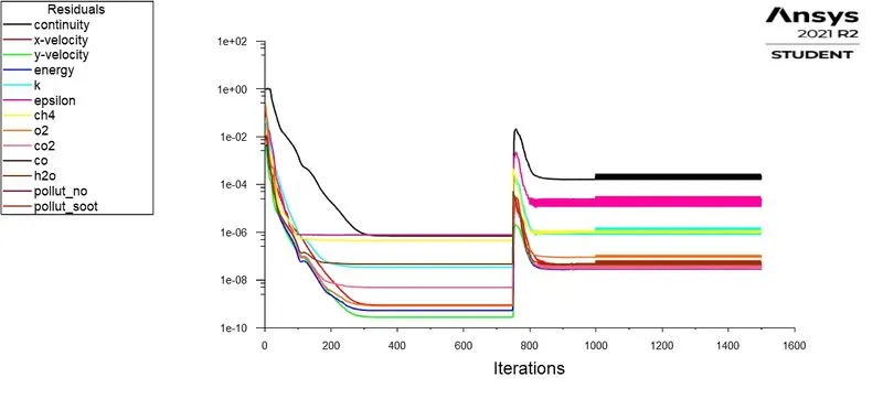
Solution is converged
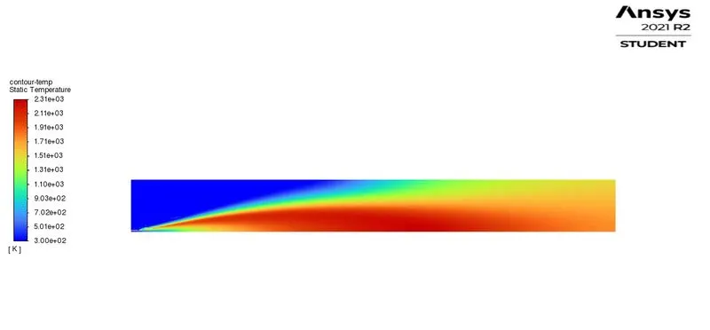
Temperature contour
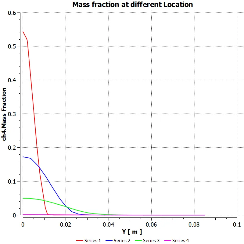
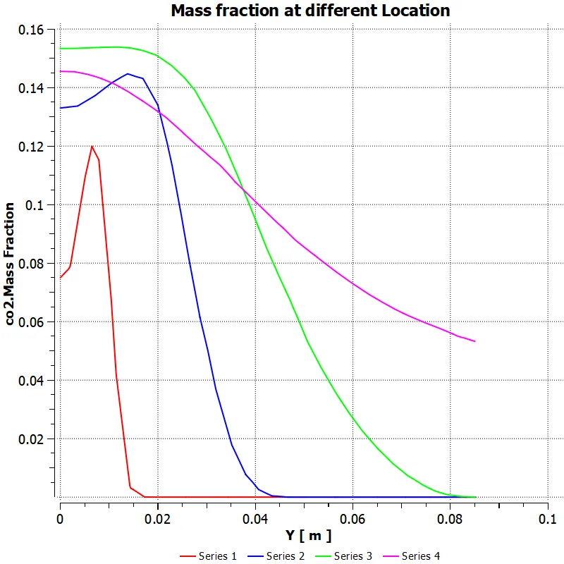
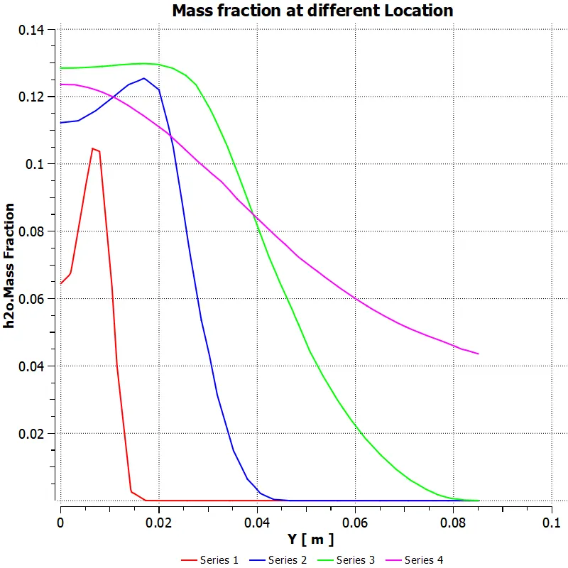
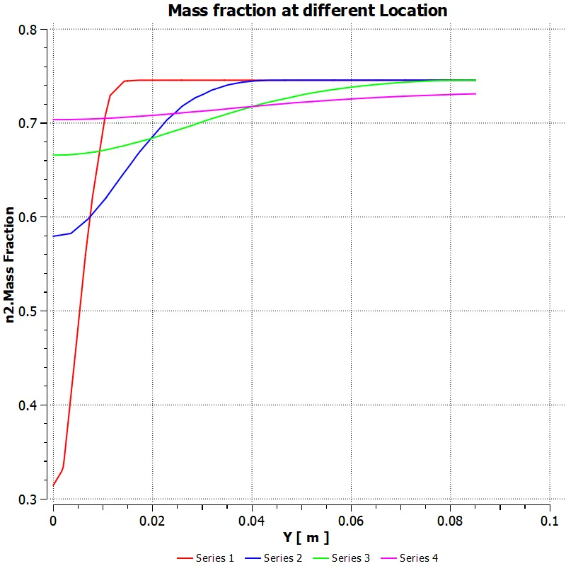
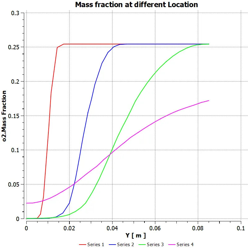
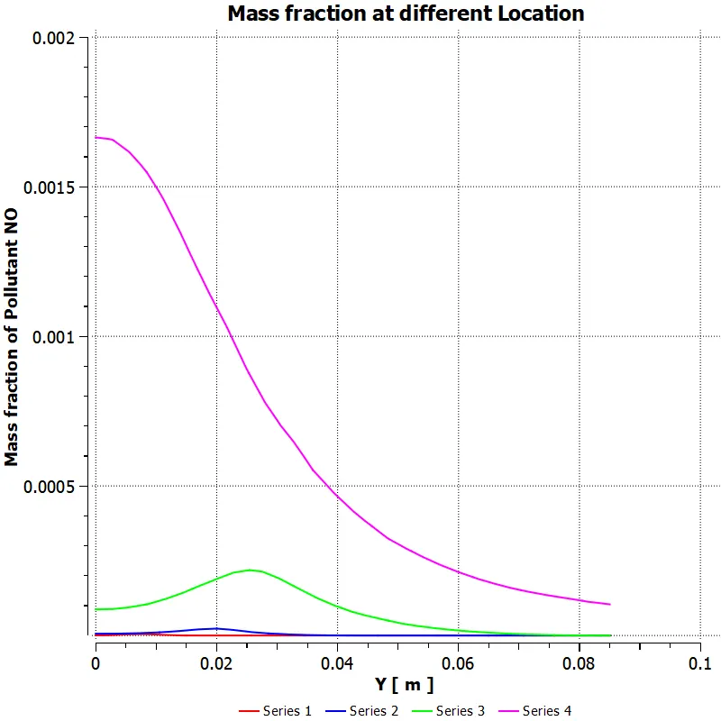
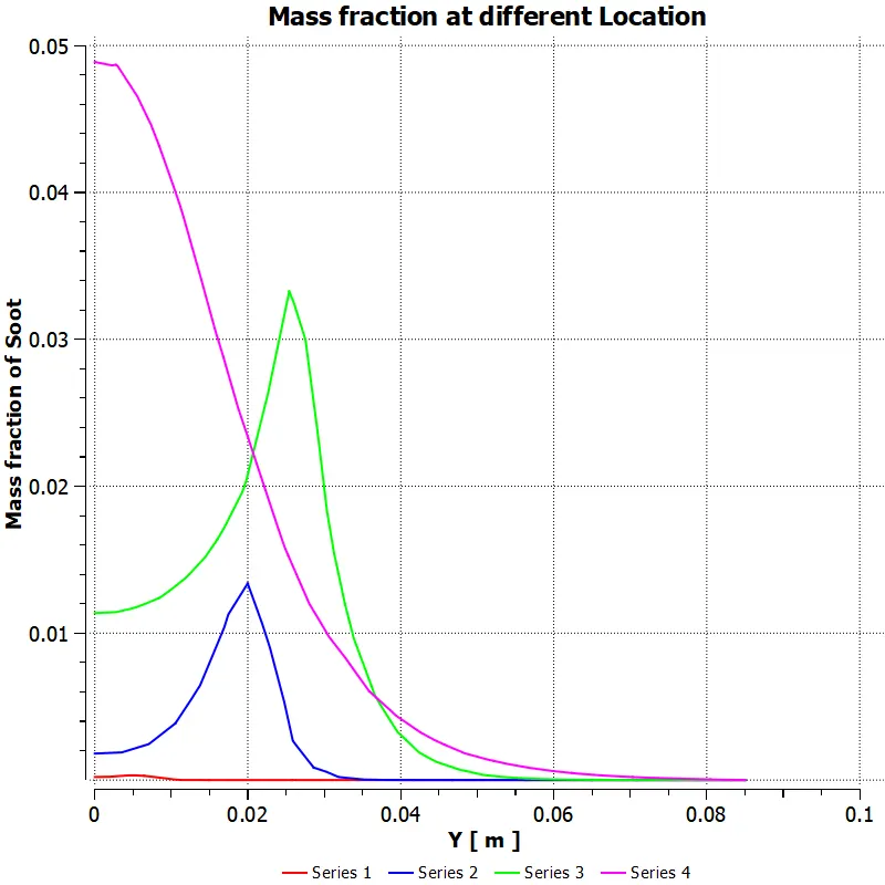
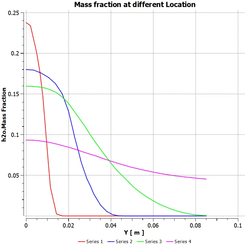
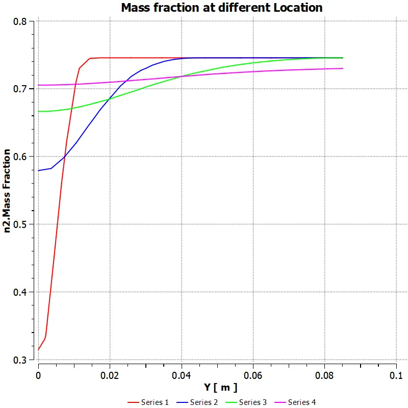
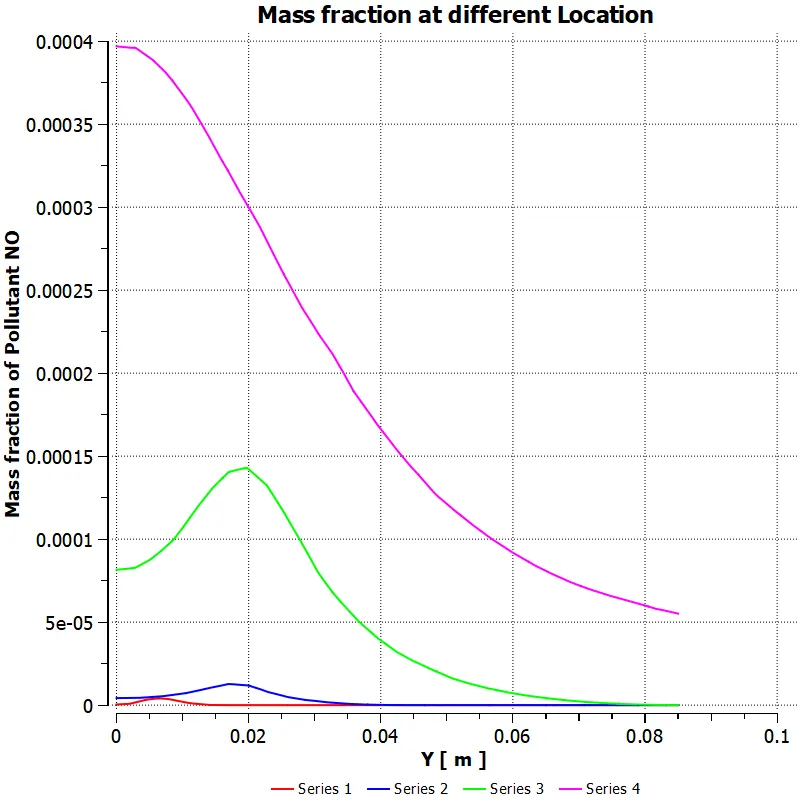
Different line locations
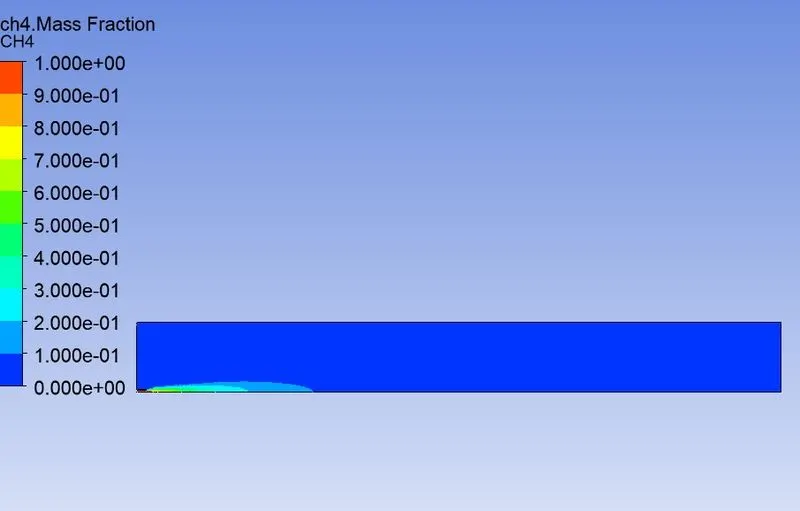
CH4 Mass fraction
CO2 Mass fraction
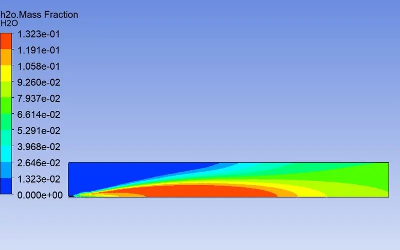
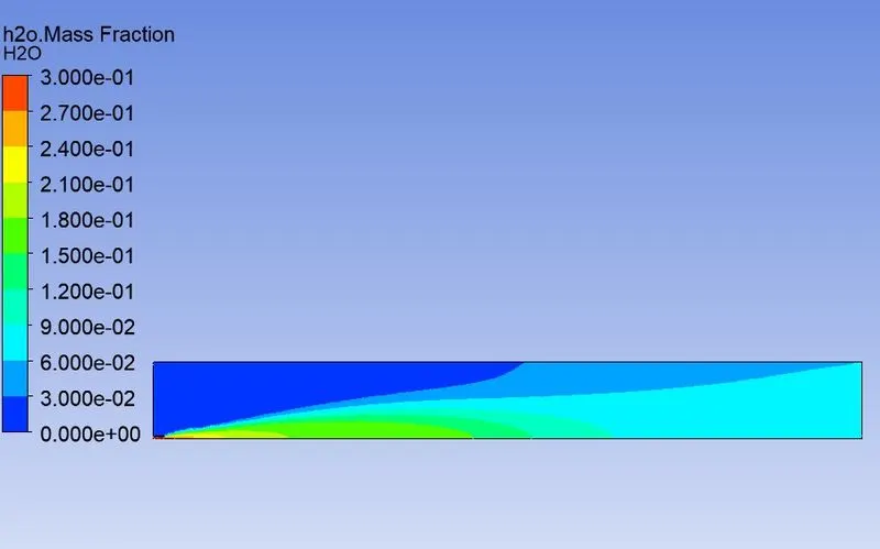
H2O Mass fraction
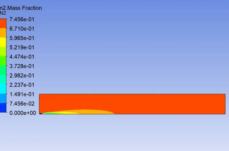
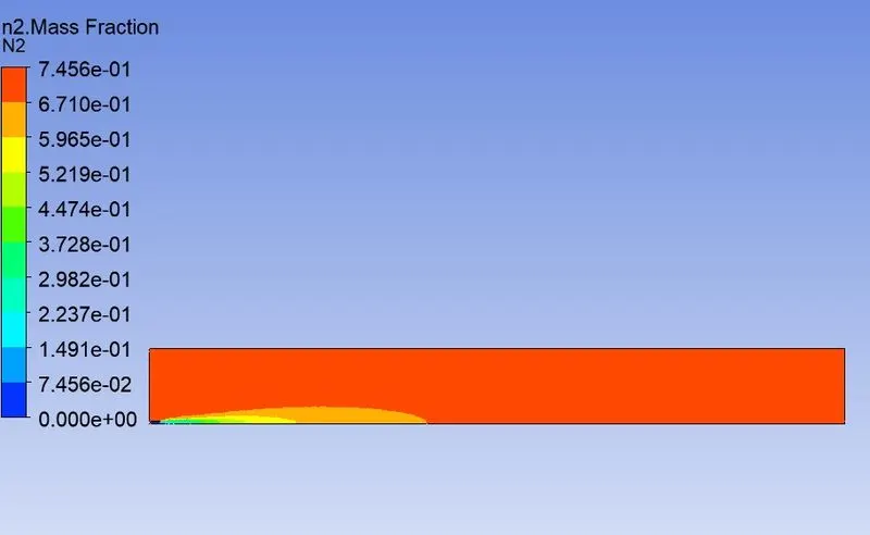
N2 mass fraction
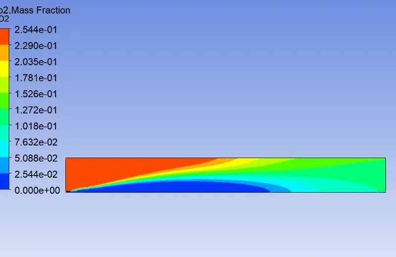
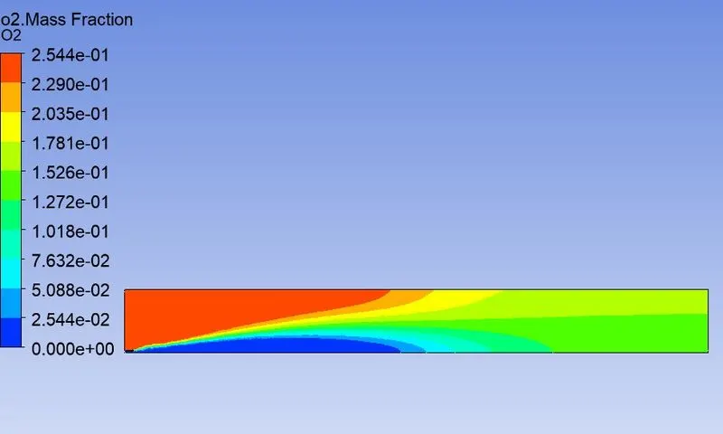
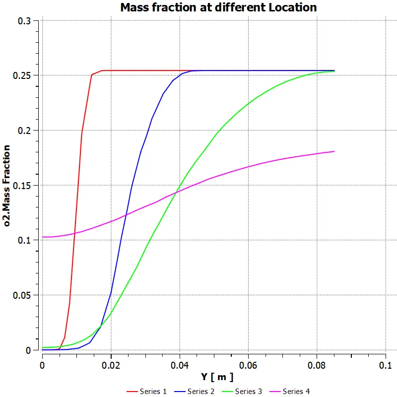
O2 Mass fraction
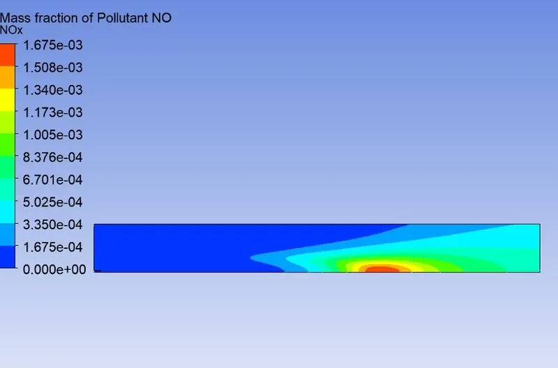
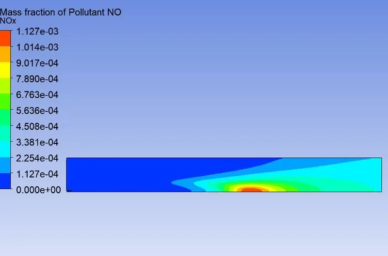
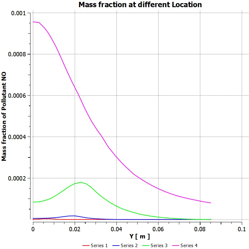
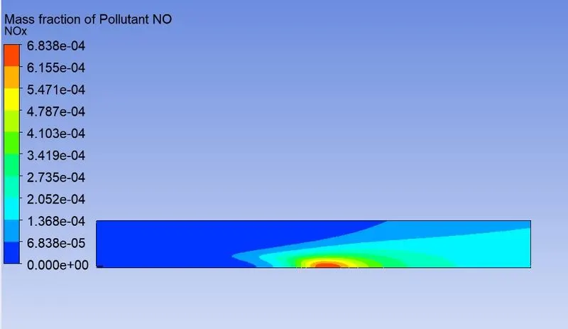
NOx Pollutant mass fraction
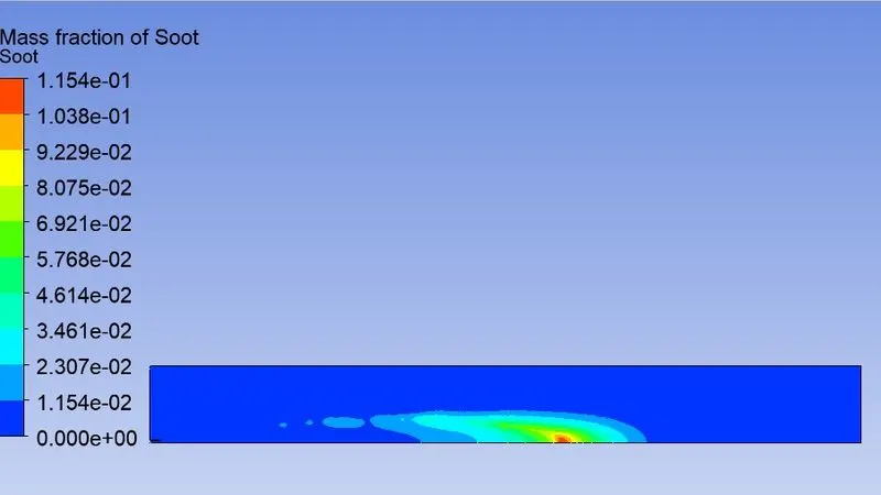
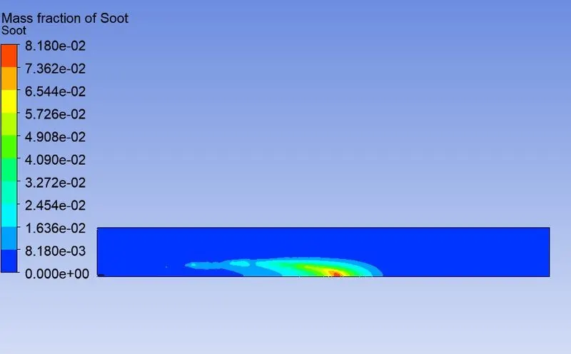
Soot formation
Part 2: Adding water to fuel.
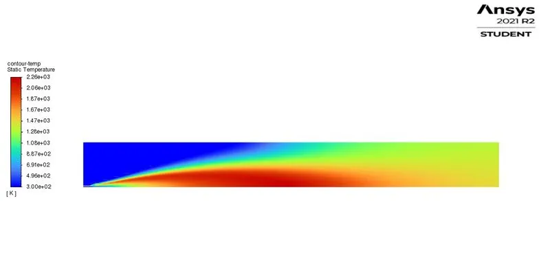
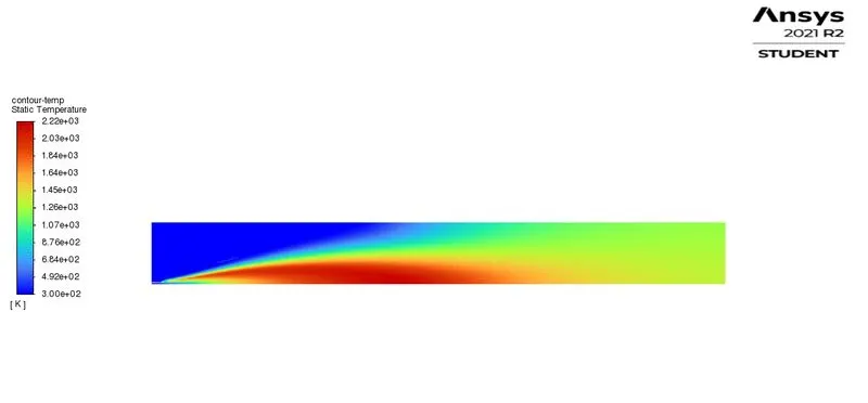
Temperature contour
 Case 2
 Case 3
 Case 4
CH4 Mass fraction
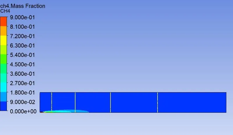
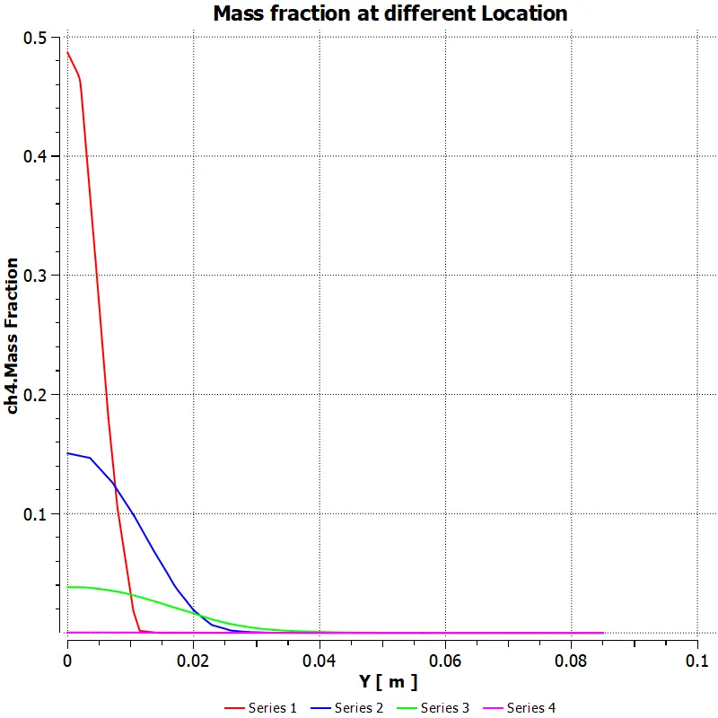 Case 2
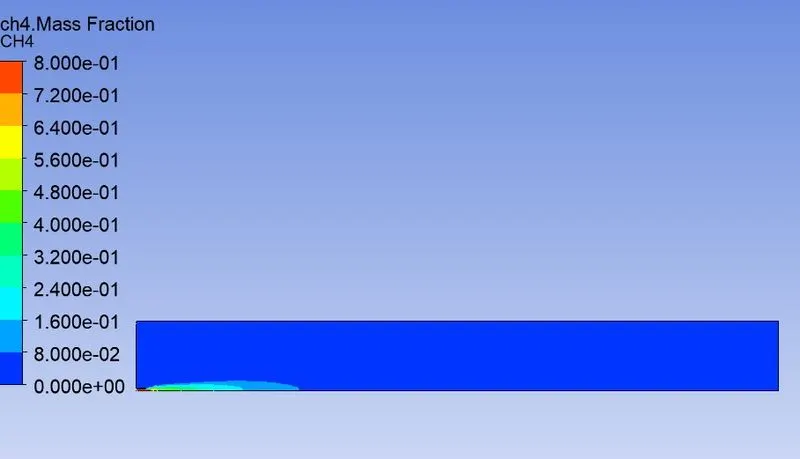
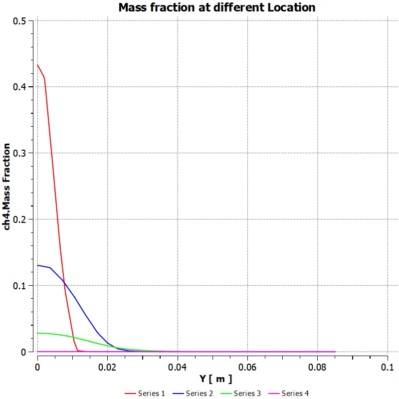 Case 3
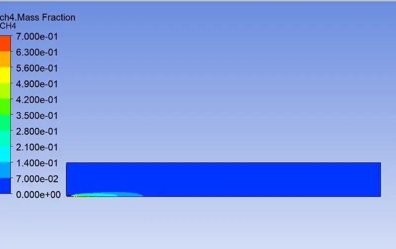
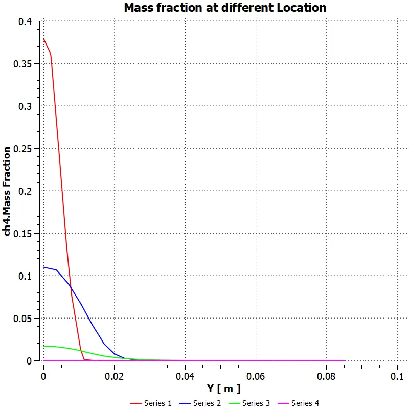 Case 4
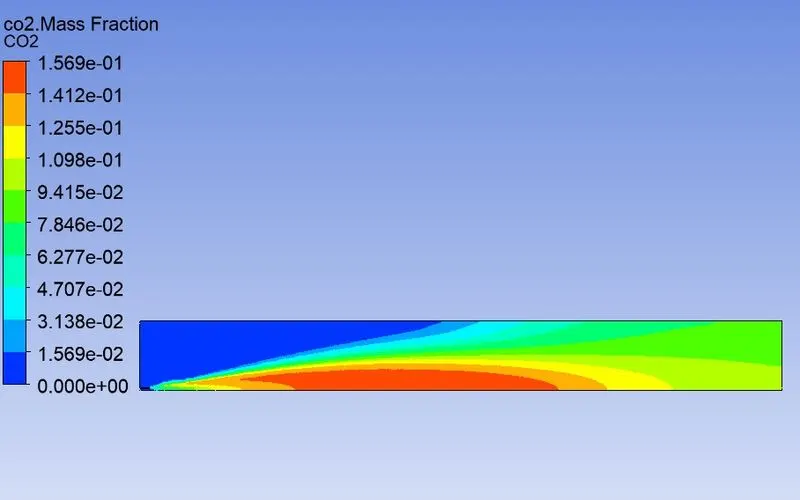
CO2 Mass fraction
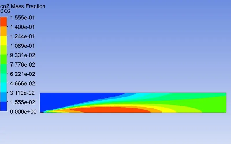
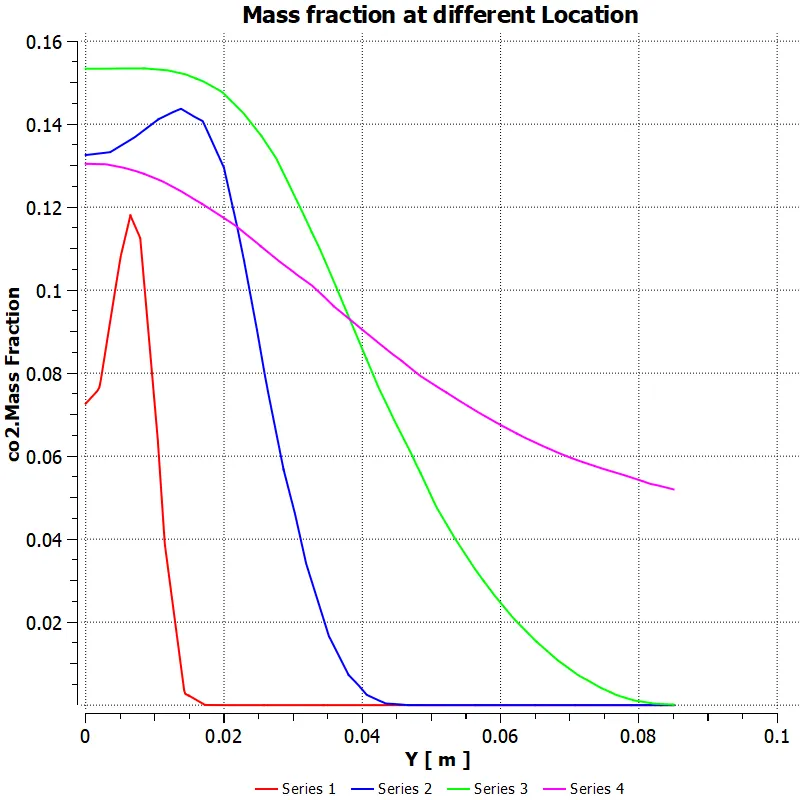 Case 2
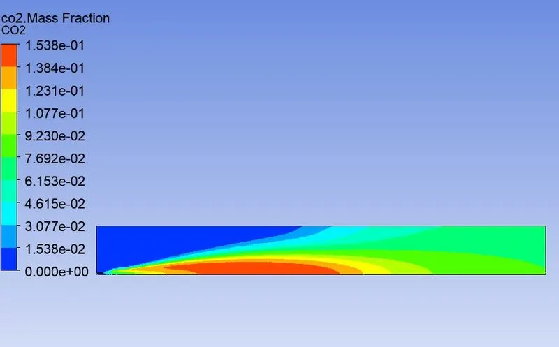
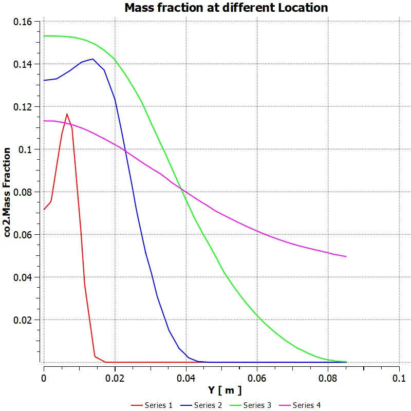 Case 3
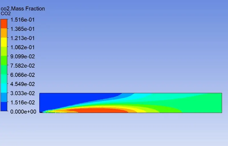
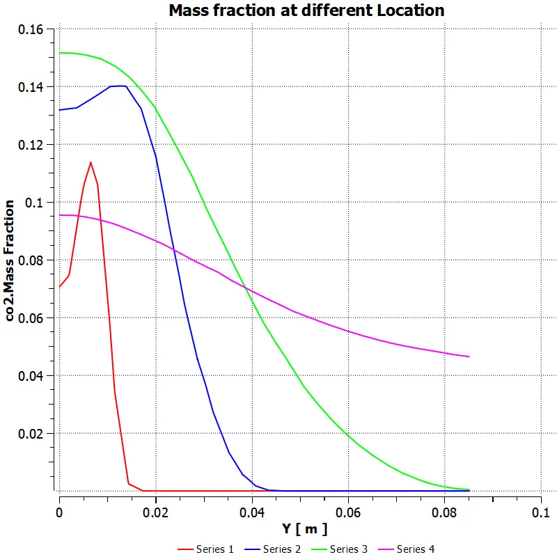 Case 4
H2O Mass Fraction
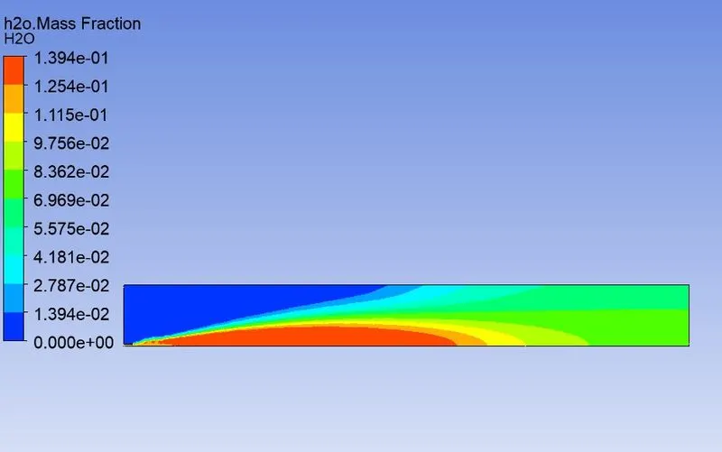
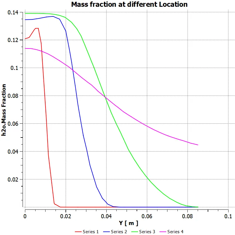 Case 2
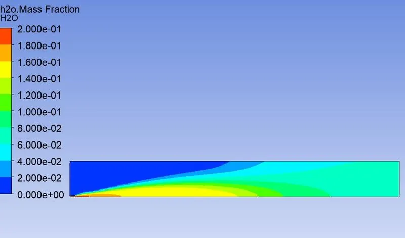
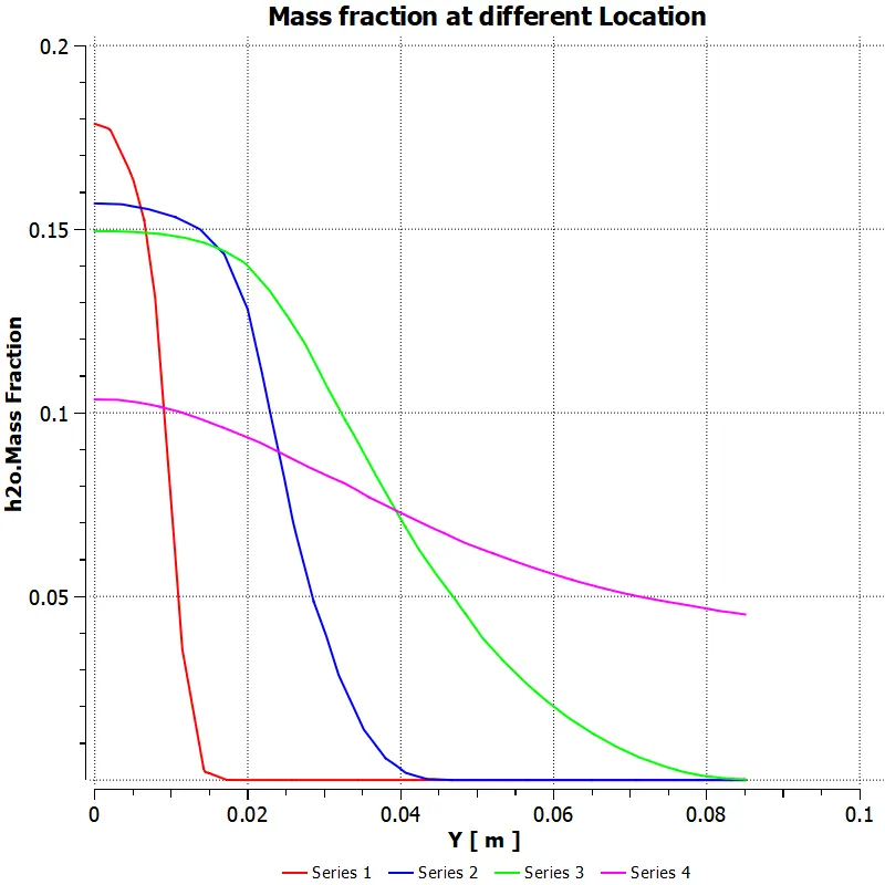 Case 3
 Case 4
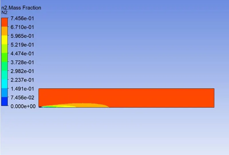
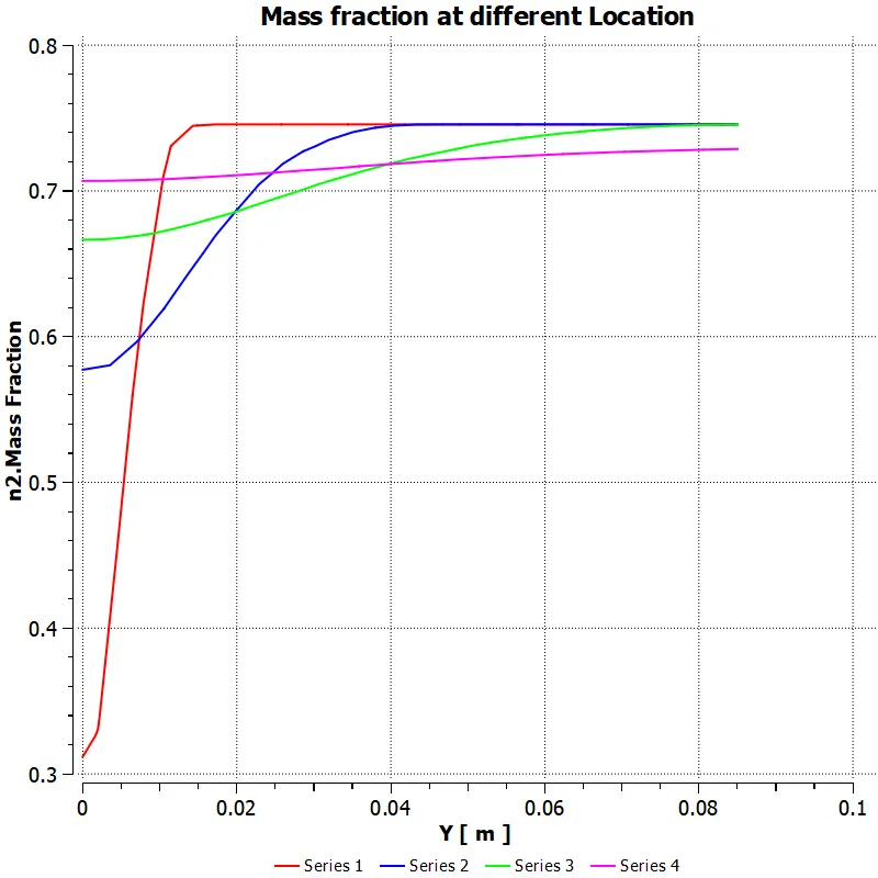
N2 Mass Fraction
 Case 2
 Case 3
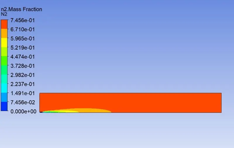
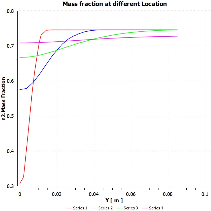 Case 4
O2 Mass fraction
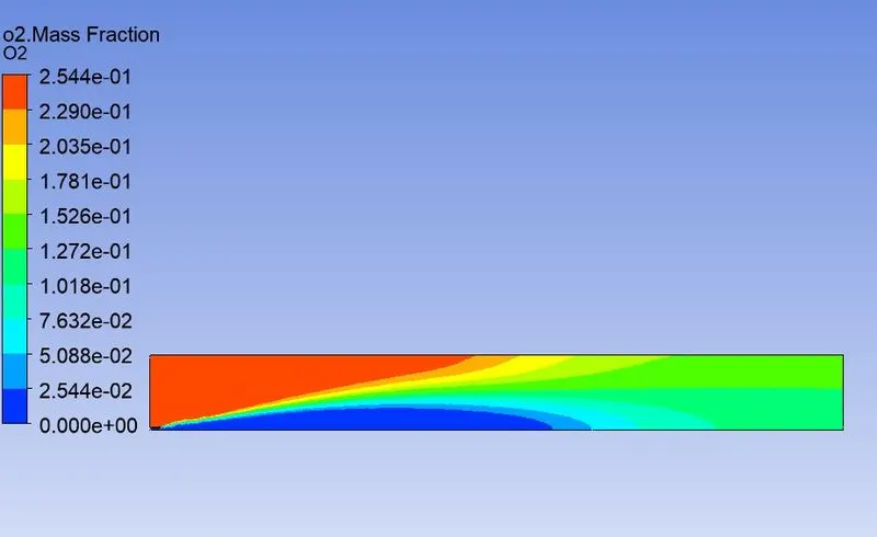
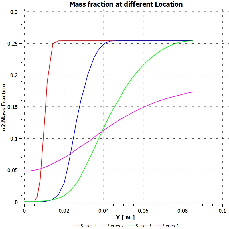 Case 2
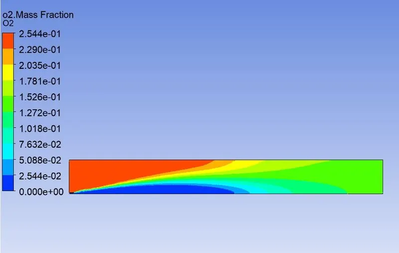
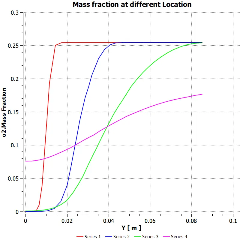 Case 3
 Case 4
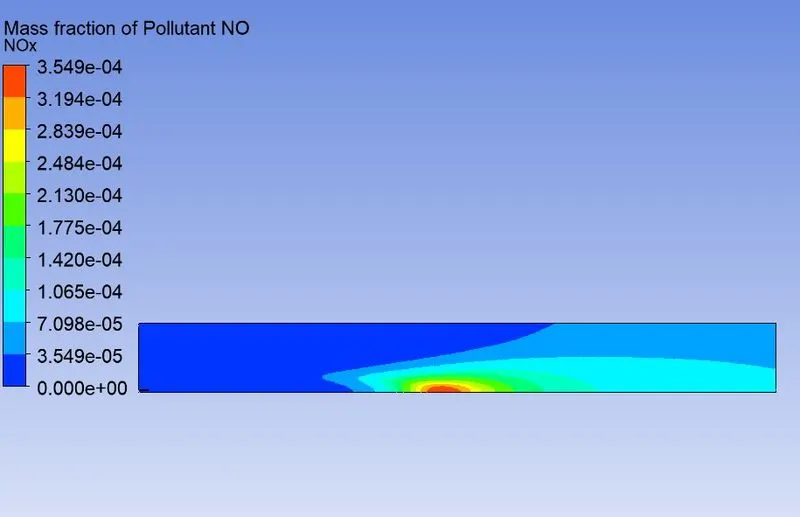
NOx Pollutant Mass Fraction
 Case 2
 Case 3
 Case 4
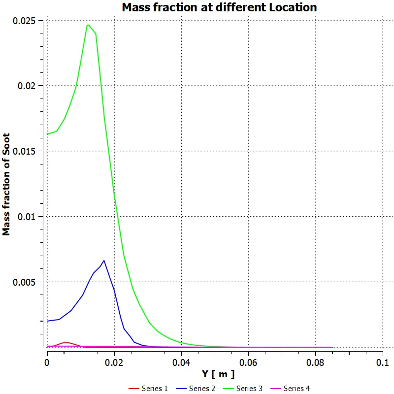
Soot Mass fraction
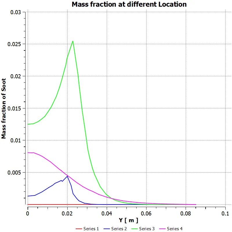 Case 2
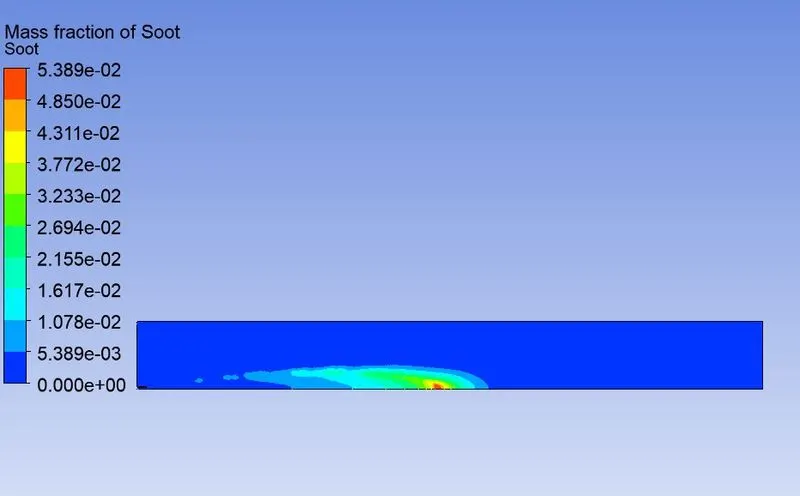
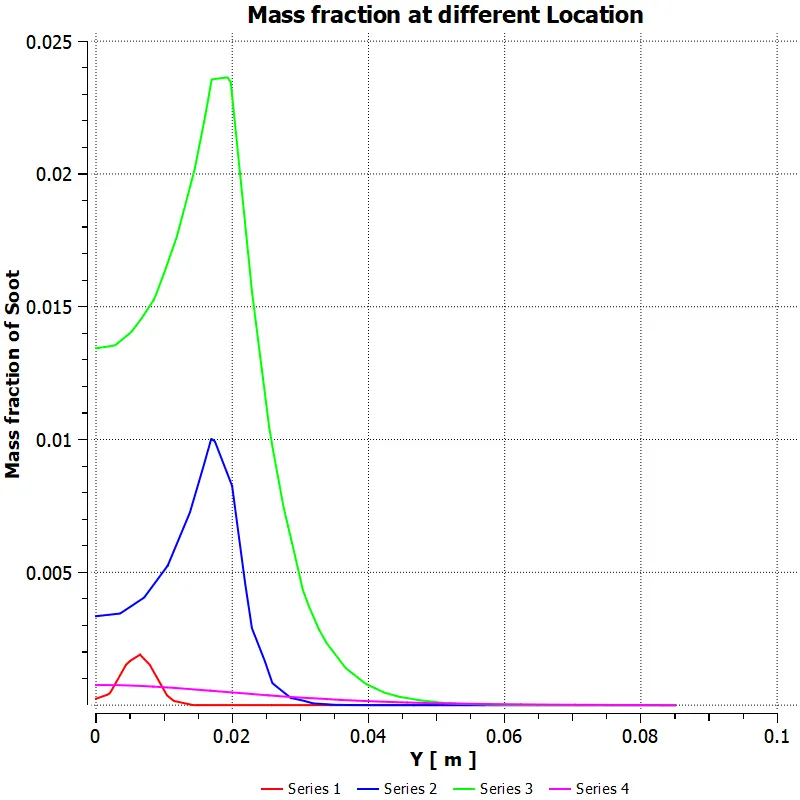 Case 3
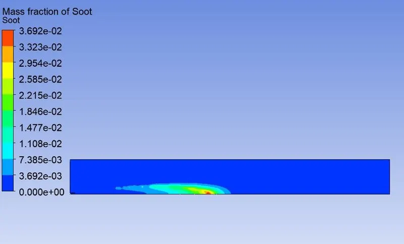
 Case 4
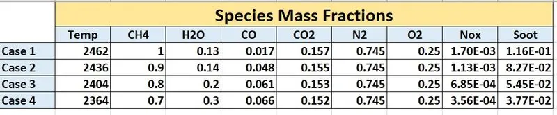
The species mass fractions from the results for different cases are tabulated below
Conclusions
- From part 1, we can see the formation of Pollutant NO and the Soot inside the combustor near the outlet.
- From the contours, we can observe that the fuel started burning from the inlet itself. As a result of these processes, we can observe the formation of maximum CO2 and H2O at the maximum temperature area, where the major combustion takes place.
- Most of the oxygen can be seen in the inlet area.
- The N2 is uniformly spread over the burning region throughout the combustor.
- From Part 2, we can see that the addition of water reduces the mass fraction of pollutants and soot. More the water content less mass fractions of pollutants and soot.
- Even though the temperature reduced slightly, there is no change in O2 and N2 fractions even if add more water
- Hence the addition of water can reduce the formation of harmful pollutants and soot.