Week 10 - Simulating Combustion of Natural Gas.
WEEK 10 - SIMULATING COMBUSTION OF NATURAL GAS
AIM:
- Perform a combustion simulation on the combustor model.
- To plot the variation of the mass fraction of the different species’ in the simulation using line probes at different locations of the combustor for CO2, H2O, CH4, N2, O2, NOx emissions & Soot formation.
- To add the water content in the fuel from 5% to 30% by mole and observe the effect of it on the results.
- To check the effect of adding the water in the fuel.
- To provide line plots and contours to prove the claim.
- To do parametric study approach if required.
THEORY:
Combustion:
- The definition of combustion is more specifically a chemical reaction in which energy is released when fuel and the oxygen in air are mixed and exposed to heat.
- There are many kinds of fuels: wood, natural gas, gasoline, diesel, ethanol and biofuels, among others. Altering the fuel, oxygen or heat availability can control combustion.
- In reality there are several different types of combustion. All combustion requires fuel, a heat source and oxygen.
Internal combustion:
- Internal combustion is a common type of combustion.
- This type of combustion happens inside an engine, which is why that type of engine is called an "internal combustion engine".
External combustion:
- An external combustion engine uses a working fluid, either a liquid or a gas or both, that is heated by a fuel burned outside the engine.
- The external combustion chamber is filled with a fuel and air mixture that is ignited to produce a large amount of heat. This heat is then used to heat the internal working fluid either through the engine wall or a heat exchanger. The fluid expands when heated, acting on the mechanism of the engine, thus producing motion and usable work.
Fuels:
The most common modern fuels are made up of hydrcarbons and are derived mostly from fossil fuels. Fossil fuels include diesel fuel, gasoline and petroleum gas, and the rarer use of propane. Except for the fuel delivery components, most internal combustion engines that are designed for gasoline use can run on natural gas or liquefied petroleum gases without major modifications. Large diesels can run with air mixed with gases and a pilot diesel fuel ignition injection. Liquid and gaseous biofuels, such as ethanol and biodiesel (a form of diesel fuel that is produced from crops that yield triglycerides such as soyabeanoil), can also be used. Engines with appropriate modifications can also run on hydrogen gas, wood gas, or charcoal gas, as well as from so-called producer-gas made from other convenient biomass. Experiments have also been conducted using powdered solid fuels, such as the magnesium injection cycle.
Oxidizers:
Since air is plentiful at the surface of the earth, the oxidizer is typically atmospheric oxygen, which has the advantage of not being stored within the vehicle. This increases the power-to-weight and power-to-volume ratios. Other materials are used for special purposes, often to increase power output or to allow operation under water or in space.
Mass fraction:
- In chemistry, the mass fraction of a substance within a mixture is the ratio of the mass of that substance to the total mass of the mixture.
- A mixture is the physical combination of two or more different substances. The types of mixtures are solutions, suspensions, and colloids.
- Expressed as a formula, the mass fraction is:
Example: The mass of the water is 300 g and the alcohol, 30 g
For water,
`w_(water) = m_(water)/(m_(water) + m_(alcohol)`
`w_(water) = 300/(300 + 30) = 0.90909`
For alcohol,
`w_(alcohol) = m_(alcohol)/(m_(alcohol) + m_(water)`
`w_(alcohol) = 30/(30+300) = 0.090909`
Chemical kinetics:
- Chemical kinetics also called reaction kinetics helps us understand the rates of reactions and how it is influenced by certain conditions.
- It further helps to gather and analyze the information about the mechanism of the reaction and define the characteristics of a chemical reaction.
Chemical kinetic modeling:
- Chemical kinetic modeling is an important tool in the analysis of many combustion systems.
- The use of detailed kinetic models in the interpretation of fundamental kinetics experiments in shock tubes and plug flow reactors is widespread. Recently these models, coupled with fluid mechanical models, have become valuable in helping to understand complex phenomena in practical combustion devices.
- Chemical kinetic reaction mechanisms are strongly hierarchical in that mechanisms for the combustion of more complex fuels contain within them submechanisms for simpler fuel molecules.
Soot:
- It is is a mass of impure carbon particles resulting from the incomplete combustion of hydrocarbons. It is more properly restricted to the product of the gas-phase combustion process but is commonly extended to include the residual fuel particles such as pyrolysed coal, cenospheres, charred wood, and petroleum coke that may become airborne during pyrolysis and that are more properly identified as cokes and char.
- Soot causes various types of cancers and lung disease.
- To reduce soot we can switch away from diesel fuels, or use more efficient, low-emission diesel engines.
- Soot residue is acidic in nature.
NOx:
- Nitrogen Oxides are a family of poisonous, highly reactive gases. These gases form when fuel is burned at high temperatures.
- NOx pollution is emitted by automobiles, trucks and various non-road vehicles.
- High levels of nitrogen dioxide are also harmful to vegetation, damaging foliage, decreasing growth or reducing crop yields.
- Nitrogen dioxide can fade and discolour furnishings and fabrics, reduce visibility, and react with surfaces.
- Nitrogen dioxide can also be measured using diffusion tubes or other methods.
- NO₂ is generally expressed in parts per billion (ppb) or micrograms per cubic meter (μg/m3) and can be communicated through the Air Quality Index (AQI) for nitrogen dioxide.
- Process modifications include using specially designed low-NOx burners, reburning, combustion staging, gas recirculation, reduced air preheat and firing rates, water or steam injection, and low excess air (LEA) firing. These modifications are capable of reducing NOx emissions by 50 to 80%.
PROCEDURE:
1. SPACECLAIM:
- First, we nedd to import the geometry file to the spaceclaim.
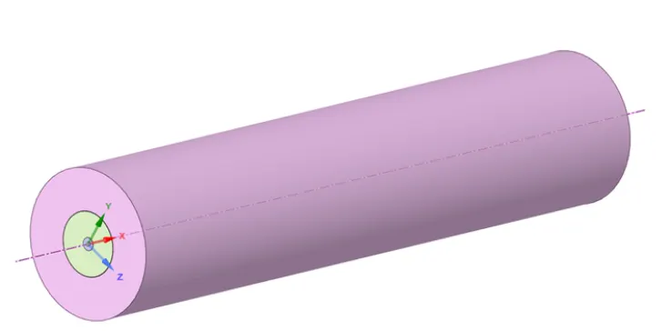
- Now we need to create 2 planes along y-axis and z-axis from the design menu.
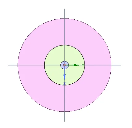
- Now we need to make axi-symmetric model. This can be done by
- First we need go design menu and select the"split body" tool.
- Now we need to select the body to be split using "target" tool.
- Then we need use cutter tool to select the required plane to be cut.
- Now we need to selct "select regions to remove" tool to remove the selected body.
- Similarly we need to do for all the other two bodies inside.
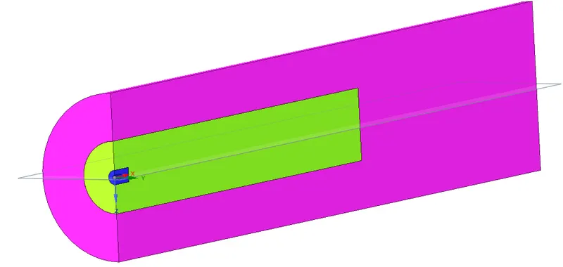

- Now we need to copy the surface into the other new design window to make into 2d geometry.

- Now we need to combine all the three surfaces into one surface. This can be done by using th combine tool which is present in the design menu.

2. MESH:
- First we need to import the mesh and do the baseline mesh.
Baseline mesh:

- Name the geometry as air inlet, fuel inlet, wall and axis.
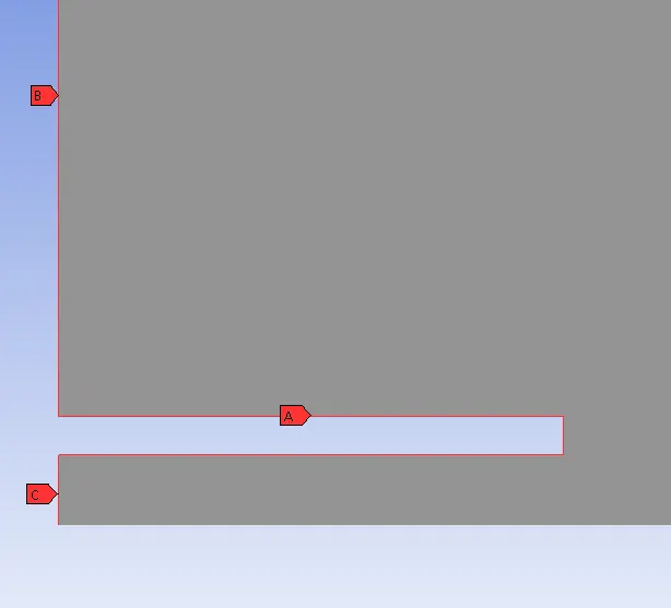

- we also need to make sure that capture proximity enabled.
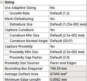
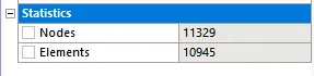
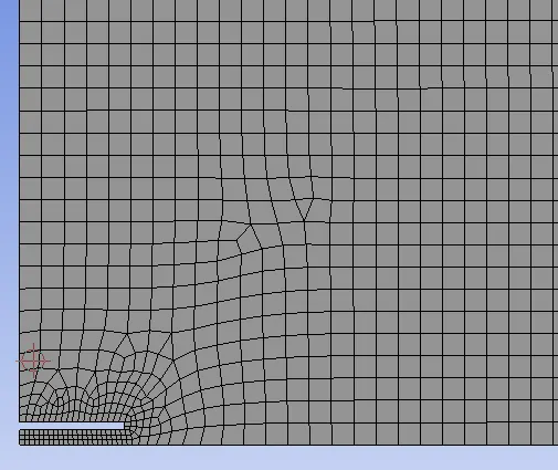
- Now we need to refine the mesh according to our needs.
Refined mesh:

3. SET-UP:
- Open the setup

- The geometry is axi-symmetric, so we need to make sure that axi-symmetric option is enabled.
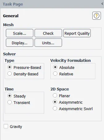
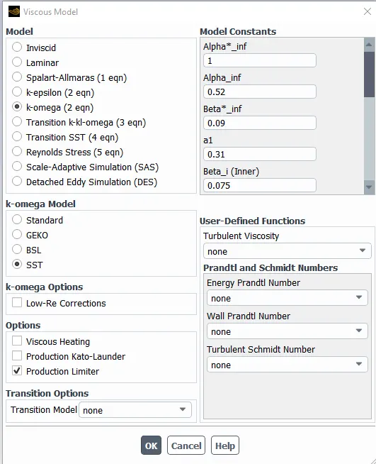
- We can use k-omega or K-epsilon model for this analysis, but here k-omega sst model is used.
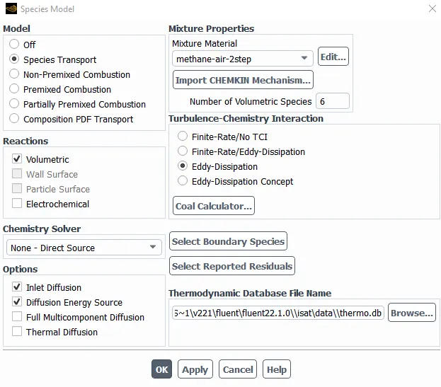
- Here we need to enable species transport, enable "volumetric", "inlet diffusion and diffusion energy source", "methane air 2 step" and enable "eddy dissipation".
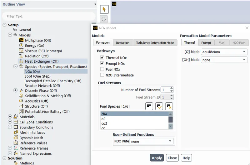
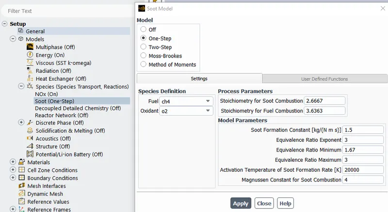
- Now we need to make sure that enable "soot" and "NOX".
- Now we need to give the boundary conditons
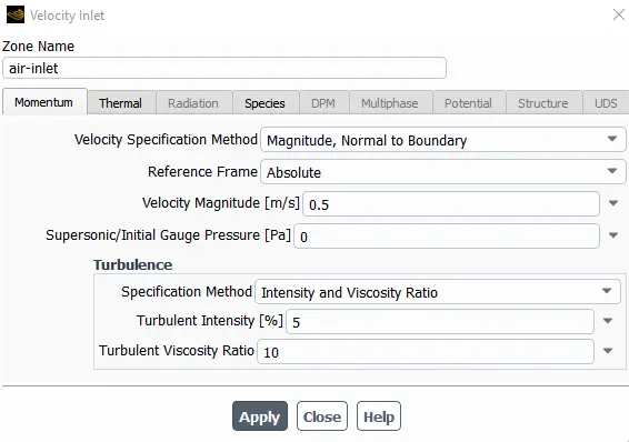
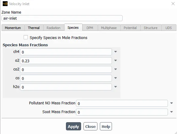
- Air inlet velocity as "0.5" m/s and in species unde O2 as "0.23"
- Now we need to give the boundary conditions for fuel inlet
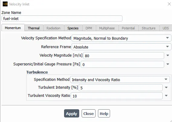
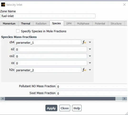
- velocity as "80" m/s and for species, we need to parametrize by creating new parameter for "CH4" as parameter 1 and "H2O" as parameter 2.
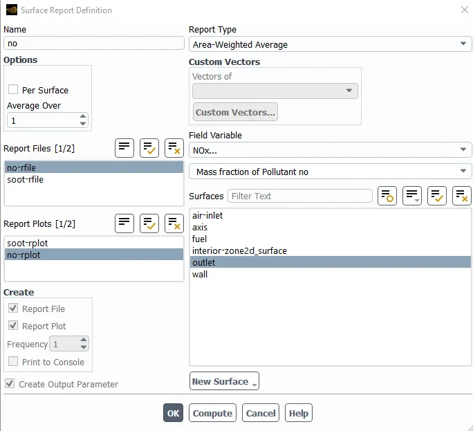
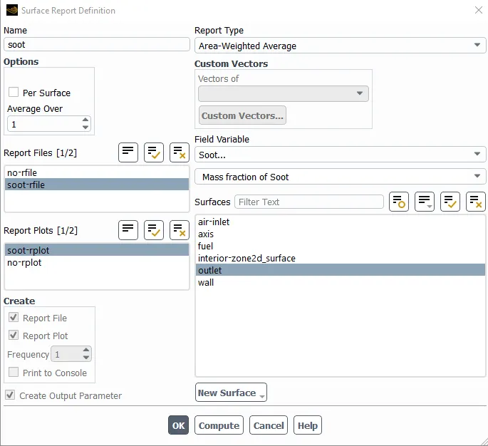
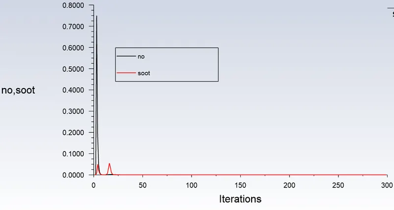
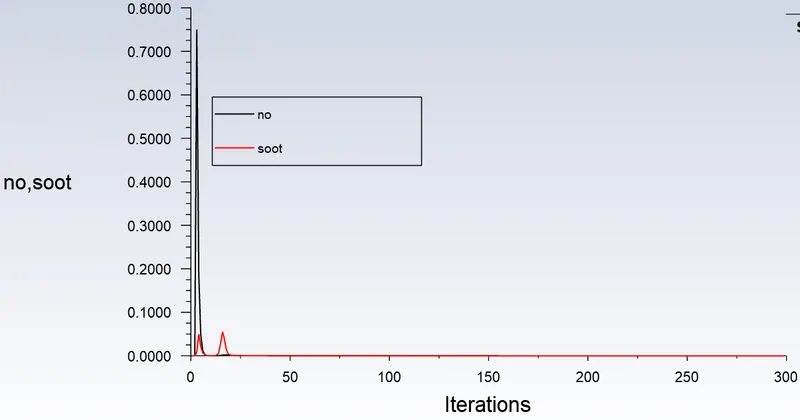
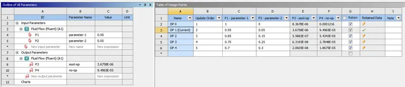
- We need to craete report definition for soot and NOX to craete a output parameter.
- Now we also need enable "create output parameter" to parametrize the analysis.
4. RESULTS:
Case-1: 100% CH4 and 0 % H2O
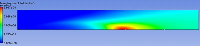
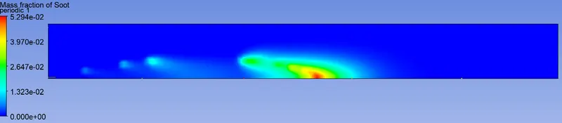
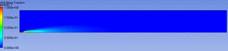
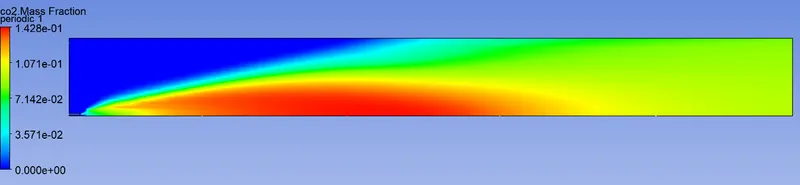
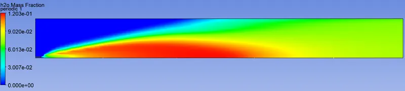
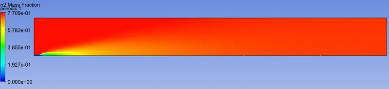
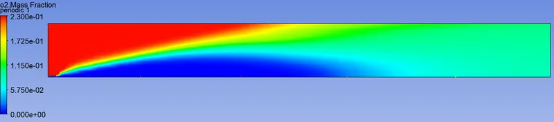
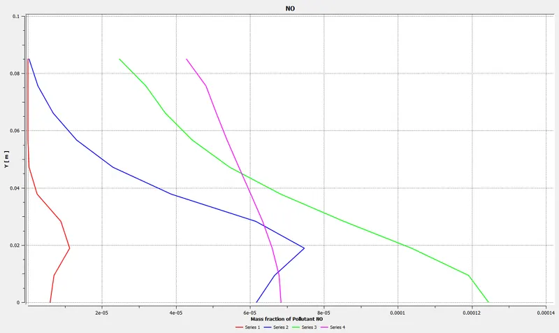
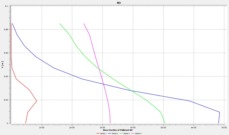
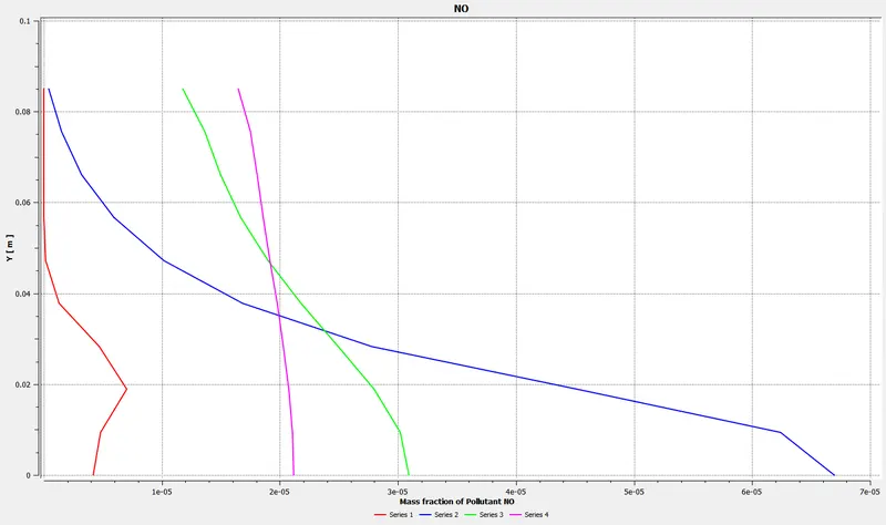
chart showing variation od mass fraction of NOX along y direction at different locations at x direction of the combustor model.
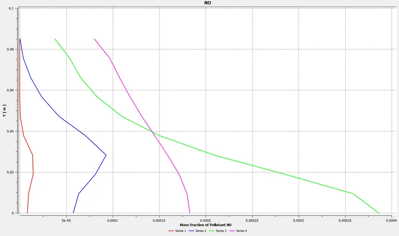
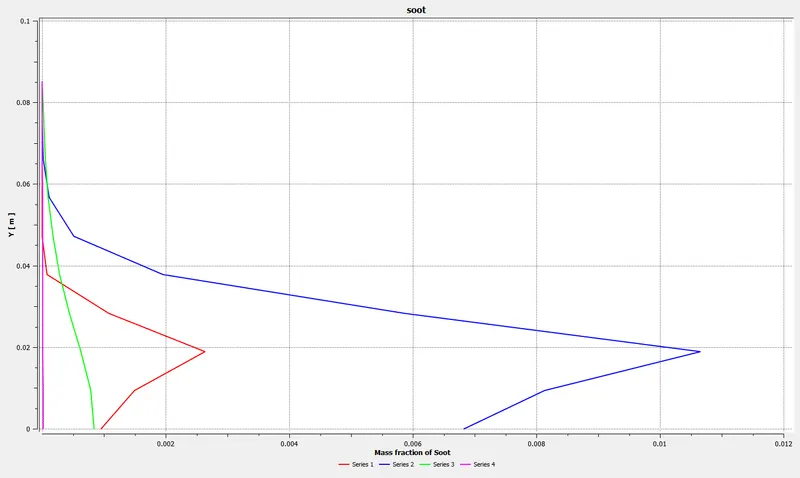
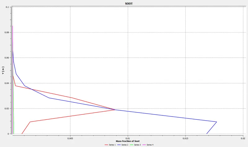
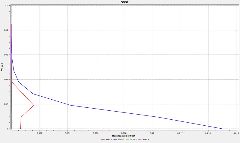
chart showing variation od mass fraction of soot along y direction at different locations at x direction of the combustor model.
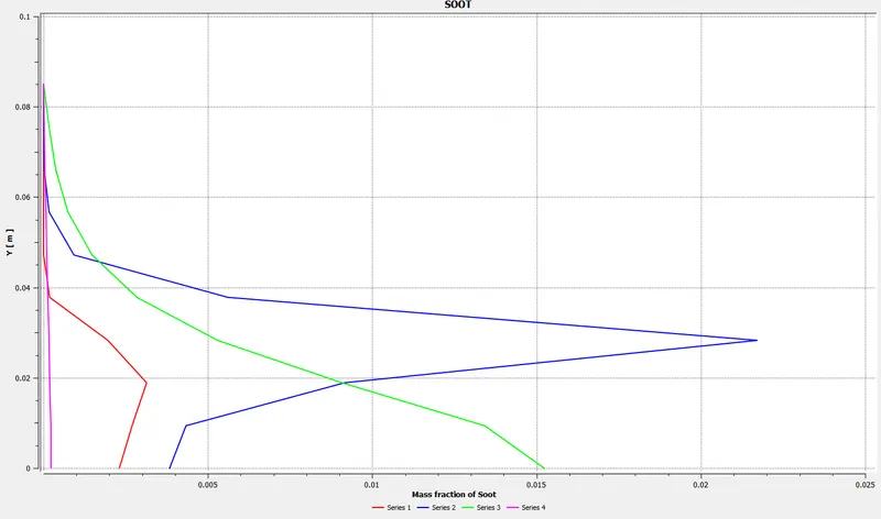
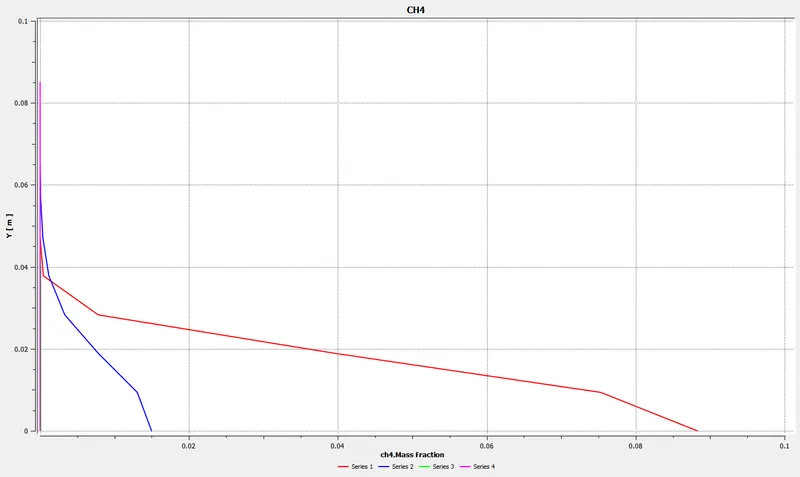
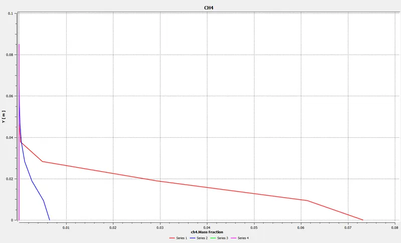
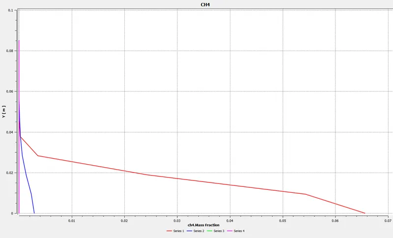
chart showing variation od mass fraction of CH4 along y direction at different locations at x direction of the combustor model.
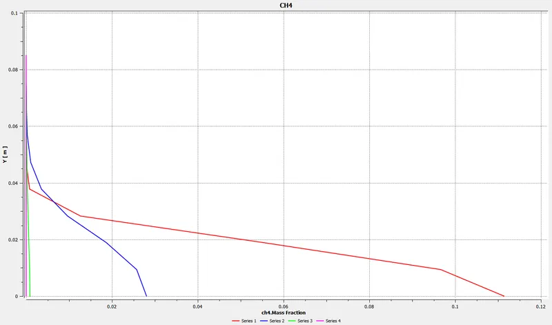
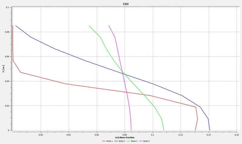
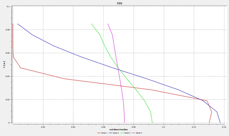
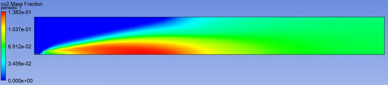
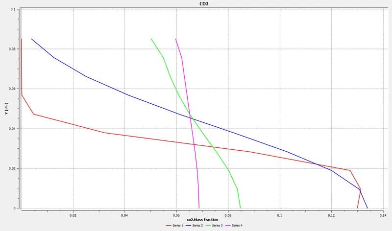
chart showing variation od mass fraction of CO2 along y direction at different locations at x direction of the combustor model.
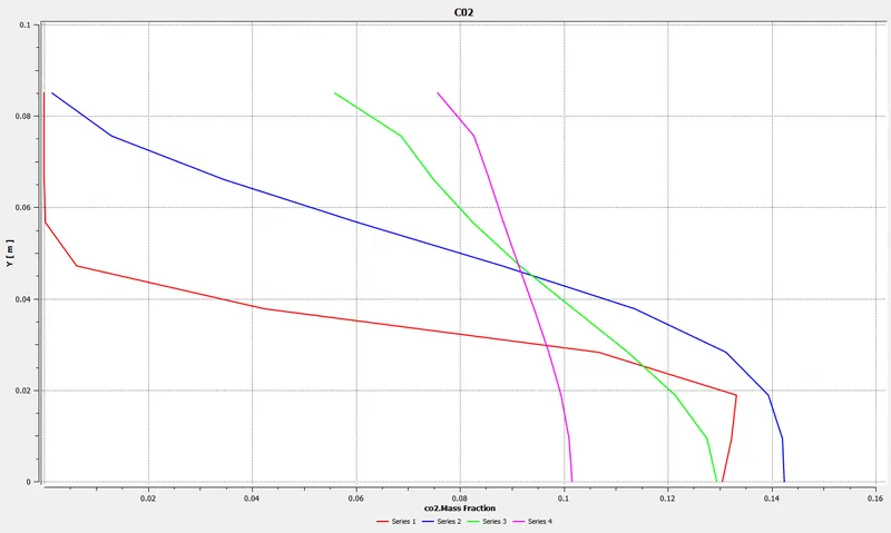
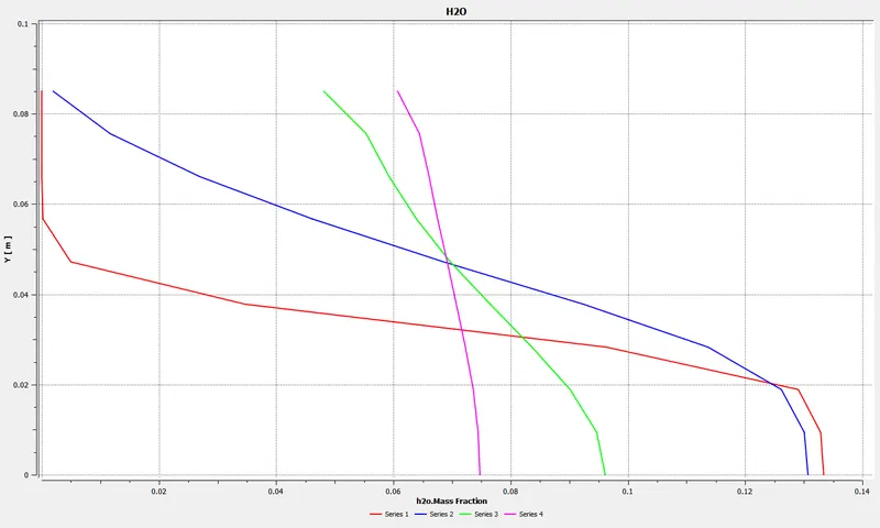
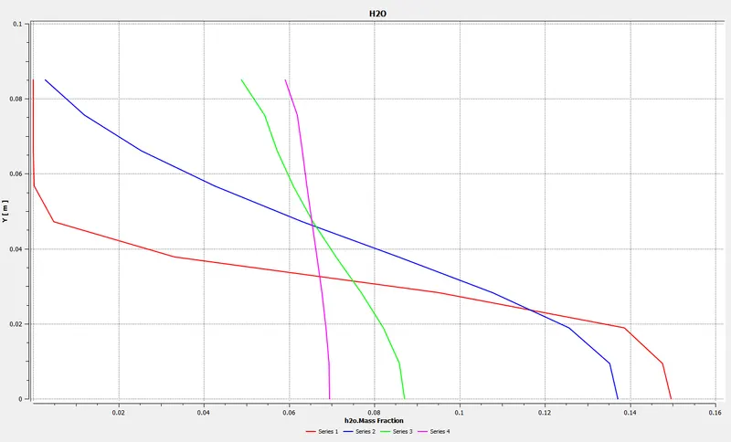
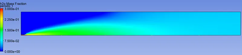
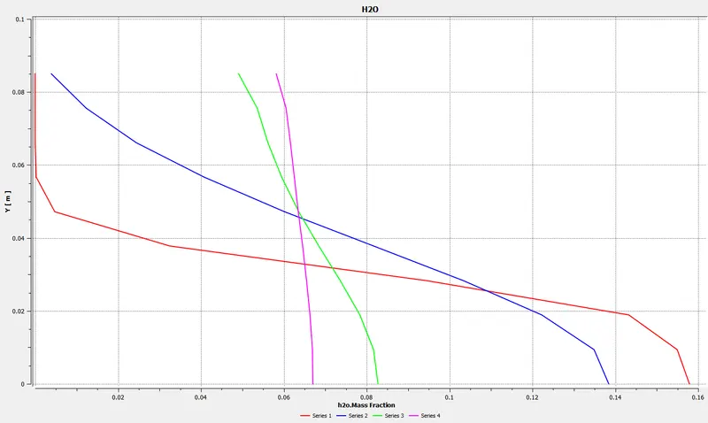
chart showing variation od mass fraction of H2O along y direction at different locations at x direction of the combustor model.
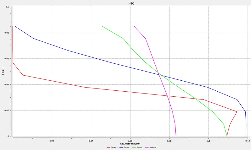
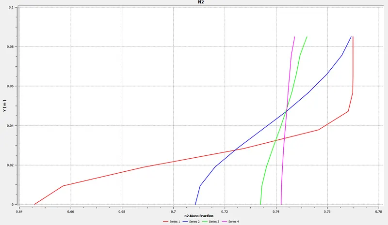
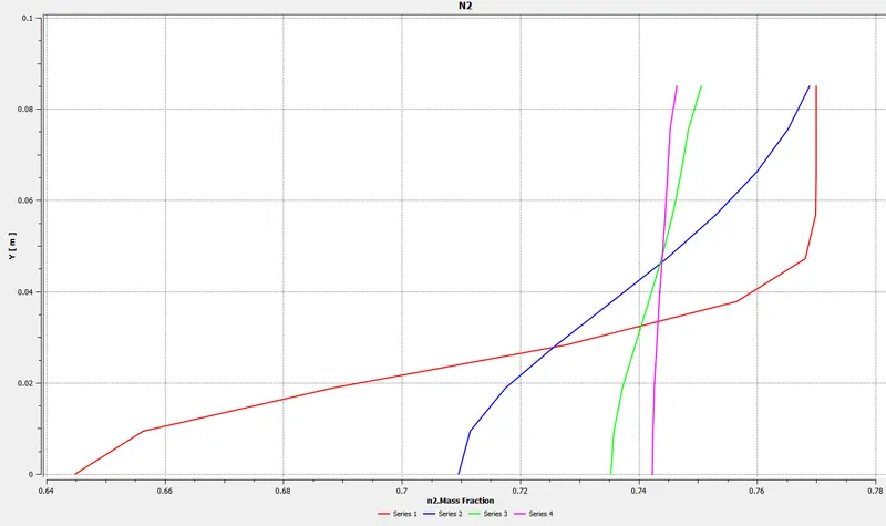
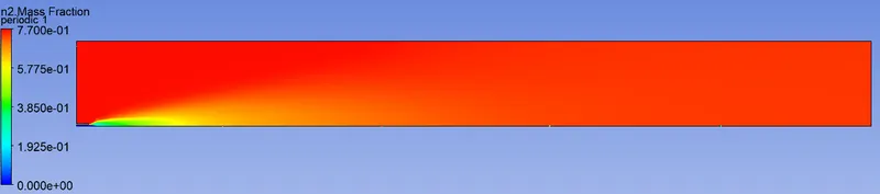
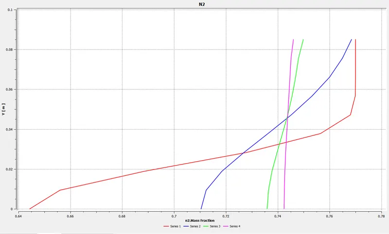
chart showing variation od mass fraction of N2 along y direction at different locations at x direction of the combustor model.
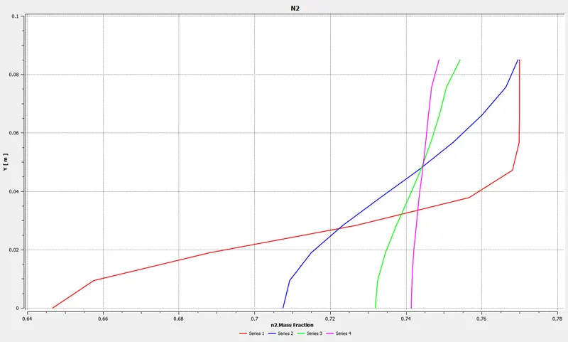
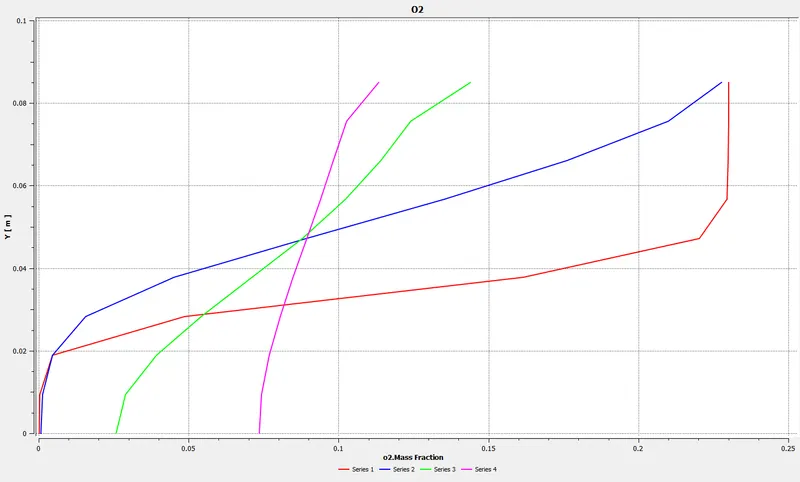
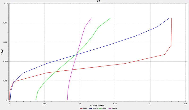
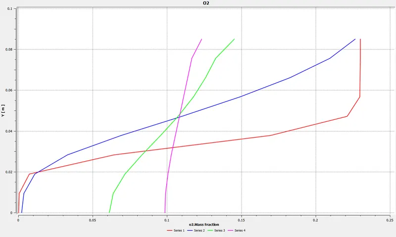
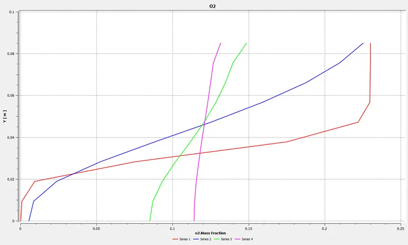
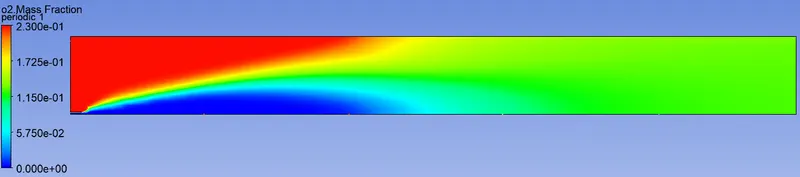
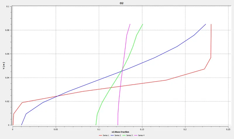
chart showing variation od mass fraction of O2 along y direction at different locations at x direction of the combustor model.
Case2: 95 % CH4 and 5 % of H20
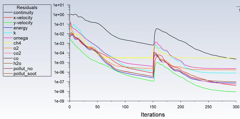
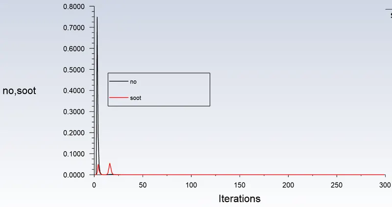
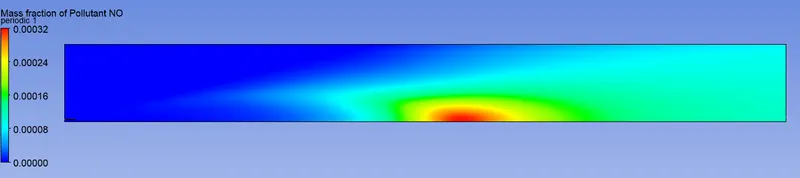
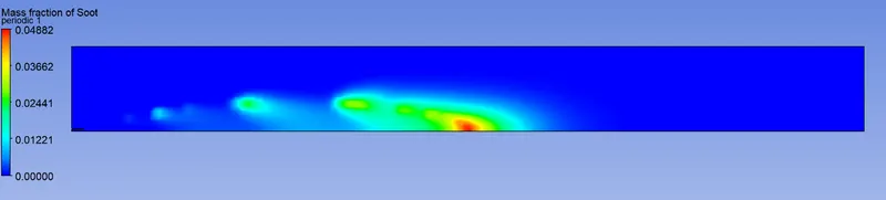

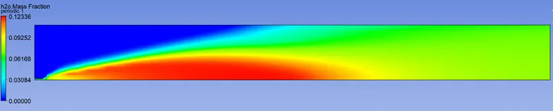

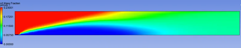
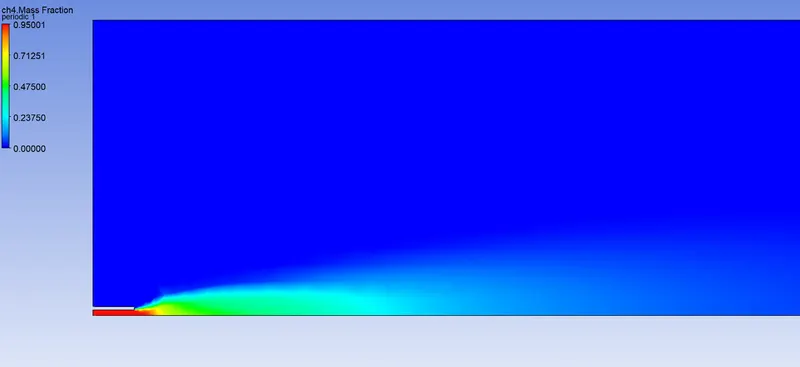
chart showing variation od mass fraction of NOX along y direction at different locations at x direction of the combustor model.
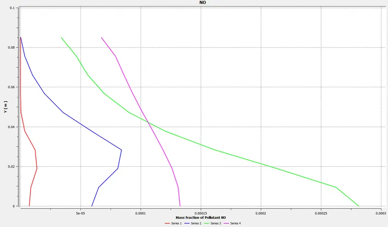
chart showing variation od mass fraction of soot along y direction at different locations at x direction of the combustor model.
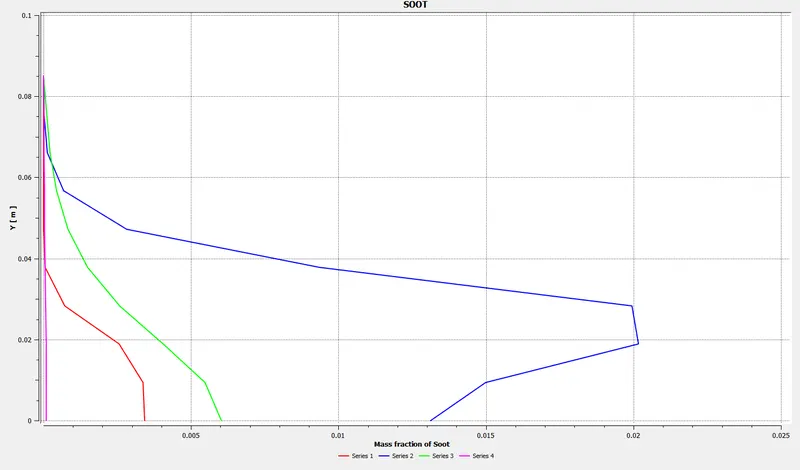
chart showing variation od mass fraction of CH4 along y direction at different locations at x direction of the combustor model.
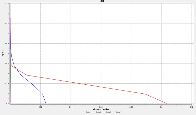
chart showing variation od mass fraction of CO2 along y direction at different locations at x direction of the combustor model.
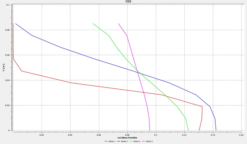
chart showing variation od mass fraction of H2O along y direction at different locations at x direction of the combustor model.
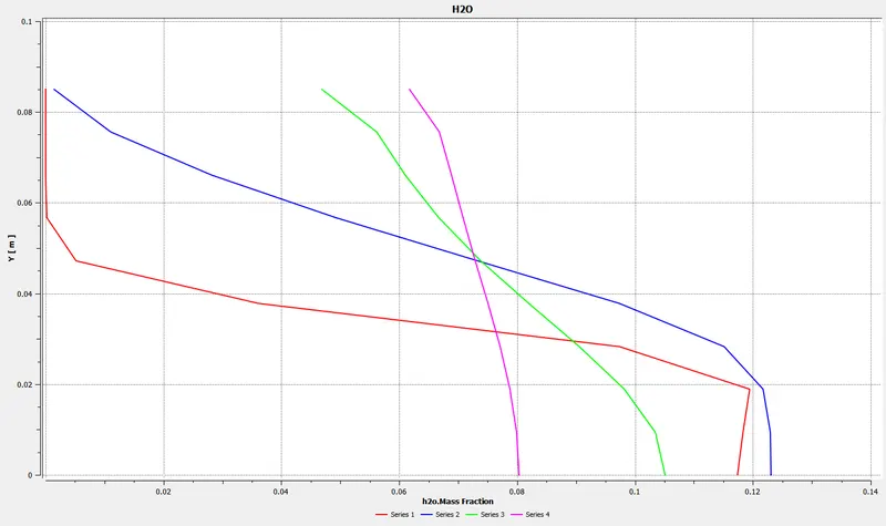
chart showing variation od mass fraction of N2 along y direction at different locations at x direction of the combustor model.
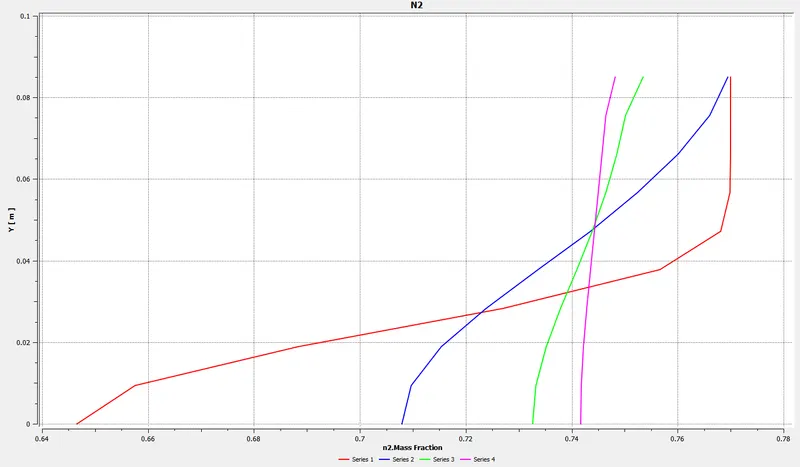
chart showing variation od mass fraction of O2 along y direction at different locations at x direction of the combustor model.
Case-3: 85 % of CH4 and 15 % of H20

Case-4: 75 % of CH4 and 25 % of H20
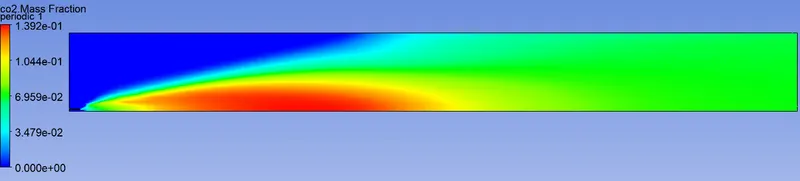
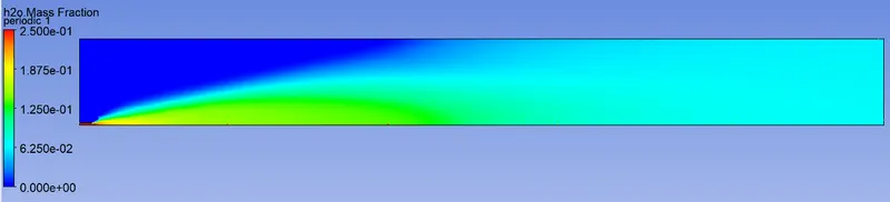
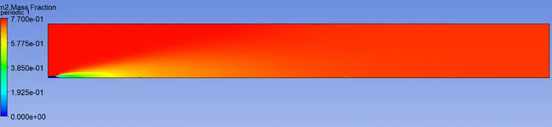
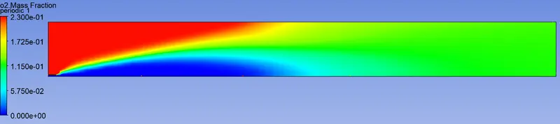
Case-5: 70 % of CH4 and 30 % of H20
Conclusion:
- Generally, efficiency of combustion reduces when water is added, which is due to reduction in flame temperature.
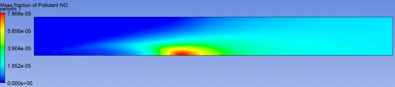
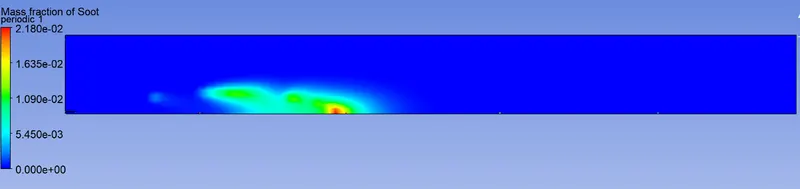
- We may deduce from the above table and charts that when water content is added, NOX emissions decrease and this is because, injection of water or steam into the flame area provides a heat sink that lowers the flame temperature and reduces thermal NOX formation and also SOOT decrease because of the chemical effect, which happens due to thermal dissociation of the water molecule into O and OH ions.
- We may infer from the above plots that CO2 is also reducing when water content is increasing and this is because when a small fraction of the CO2 that dissolves in water reacts rapidly to form carbonic acid. This, in turn, partially dissociates to form hydrogen, bicarbonate and carbonate ions. CO2 will continue to dissolve until equilibrium is reached.
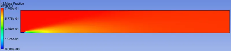
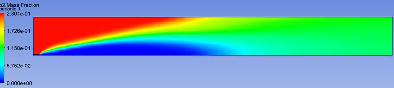
- From the above plots, we can observe that O2 and N2 gets increased when the water is added and also nitrogen reduces combustion efficiency by absorbing heat from the combustion of fuels and diluting the flue gases. This reduces the heat available for transfer through the heat exchange surfaces.
- The NOX, SOOT, CH4, H20, CO2 decreases along the y direction at all x locations of the combustor model.
- The N2 and O2 increases along the y direction at all x locations of the combustor model.
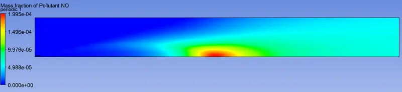
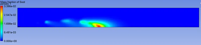
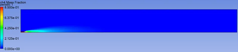
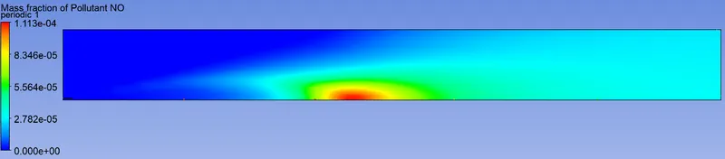
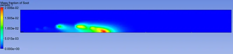
- We may conclude from the contours that the mass fraction of SOOT and NOX is relatively high near the halfway point of the combustor model, implying that most of the stuff settles there.
- We may infer from the contour that N2 matter takes up the majority of the space in the model, owing to its high mass percentage.
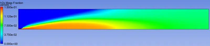
- From the above contours, we can determine that the mass fraction of H2O and CO2 is very high from the flame point to 40% of the length of the combustor model.
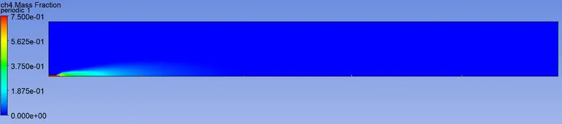
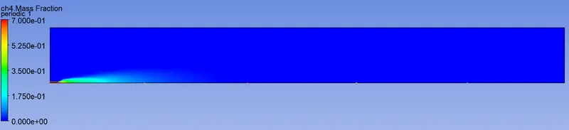
- From the above contours, we can say that mass fraction is high from the beginning to the 40 % of the length of the combustor model.