Week 10 - Simulating Combustion of Natural Gas.
Aim :
To perform a combustion simulation on the combustor model using Ansys Fluent.
Objective :
- To perform a combustion simulation on the combustor model.
- To plot the variation of the mass fraction of the different species’ in the simulation using line probes at different locations of the combustor for `CO_2`, `H_2O`, `CH_4`, `N_2`, `O_2`, `NO_x` emissions & Soot formation.
- To add the water content in the fuel from 5% to 30% by mole and observe the effect of it on the results.
Theory :
Combustion is actually a scientific term for burning. We are all aware of burning, but did you know that burning is actually a chemical reaction? Combustion is a chemical process where any fuel has a reaction with air (oxidant) to produce heat energy. And when this heat energy release it will also produce light in the form of a flame. This is the visible part of the reaction, the flames. The general exothermic reaction of combustion can be expressed as:
Hydrocarbon + Oxygen → Carbon Dioxide + Water + Heat Energy
Examples of Combustion :
- Burning of Wood or Coal to heat your home
- Burning of Petrol or Diesel to run your Car
- Combustion of Natural Gas or LPG to cook for on your stovetop
- For the production of energy in thermal power plants
- Fireworks
Types of Combustion :
1] Complete Combustion :
- One of the types of combustion is Complete Combustion. Complete combustion occurs in an unlimited supply of air, oxygen in particular. Also, complete combustion is also known as clean combustion. Here the hydrocarbon will burn out completely with the oxygen and leave only two byproducts, water, and carbon dioxide.
- An example of this is when a candle burns. The heat from the wick will vaporize the wax which reacts with the oxygen in the air. The two products of the reaction are water and carbon dioxide. In an ideal situation all the wax burns up and complete combustion takes place
2] Incomplete Combustion :
- Incomplete combustion takes place when the air is in limited supply. And as opposed to complete combustion it is otherwise known as dirty combustion. Due to lack of oxygen, the fuel will not react completely. This, in turn, produces carbon monoxide and soot instead of carbon dioxide.
- An example is burning of paper. It leaves behind ash (a form of soot) as a byproduct. In a complete combustion, the only products are water and carbon dioxide. Also, incomplete combustion produces less energy than complete combustion.
3] Rapid Combustion :
- Another type of combustion is Rapid Combustion. Rapid energy needs external heat energy for the reaction to occur. The combustion produces a large amount of heat and light energy and does so rapidly. The combustion will carry on as long as the fuel is available.
- An example is when you light a candle. The heat energy is provided when we light the candle with a matchstick. And it will carry on till the wax burns out. Hence it is a rapid combustion
4] Spontaneous Combustion :
- As the name suggests the combustion occurs spontaneously. This means that it requires no external energy for the combustion to start. It happens due to self-heating. A substance with low-ignition temperatures gets heated and this heat is unable to escape.
- The temperature rises above ignition point and in the presence of sufficient oxygen combustion will happen. The reaction of alkali metals with water is an example.
5] Explosive Combustion :
Explosive Combustion happens when the reaction occurs very rapidly. The reaction occurs when something ignites to produce heat, light and sound energy, The simple way to describe is it to call it an explosion. Some classic examples are firecrackers or blowing up of dynamite.
Major Pollutants from Combustion :
Nitrogen Oxide (`NO_x`) :
- Nitrogen oxide comprises majorly NO (nitric oxide). But Two other oxide of nitrogen such as Nitrogen Peroxide and N2O (Nitrous oxide) can be formed
- Nitric oxide (NO) reacts with oxygen or excess air to form NO2
- NOx is Highly regulated pollutant Which can results photochemical smog, This pollutant contributes ozone depletion and acid rain
- There are four different mechanisms to form NOx: Thermal, Prompt, Fuel and N2O route
Soot Particles :
- Soot particles are generally formed due to incomplete combustion or pyrolysis in rich mixture of hydrocarbon fuel with strong temperature gradients in combustion chamber
- Aggregates of Spherical carbon particles are observed within flames. Soot observed in domestic fires or chimneys contains few aggregates but large amounts of particulate fragments of coke or char are found.
- Formation of soot particle is a complex phenomenon: nucleation, surface growth, coalescence, aggregation
Overview of NOx formation mechanism :
Thermal NOx :
- Oxidation of atmospheric nitrogen
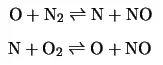
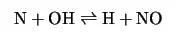
- Formed at high temperatures by the Zeldovich mechanism
- User chooses [O] model as equilibrium or partial equilibrium (recommended)
- Thermal NO formation proposed by Zeldovich Mechanism is given as
Prompt NOx :
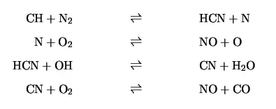
- Produced in lower temperature, fuel rich regions
- Formed predominantly through the intermediate HCN
Fuel NOx :
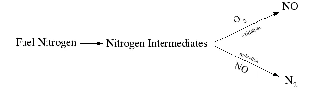
- Oxidation of volatile nitrogen to HCN and/or `NH_3`
- Oxidation of char nitrogen to NO, HCN and/or `NH_3`
- FLUENT solves an additional transport equation for HCN and/or `NH_3` mass fraction
NOx from intermediate N20 :
- Favorable under elevated pressure and oxygen rich conditions
- Additional transport equation for `N_2O` is solved if steady state approximation is not used
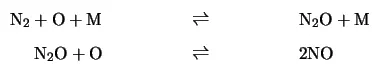
- Here M is the third body.
Geometry :
Import the geometry in the spaceclaim :
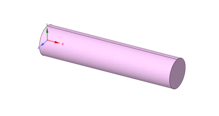
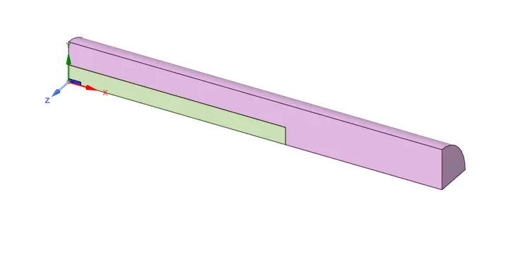
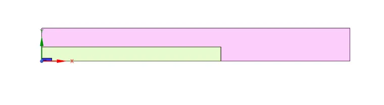
Conducting simulation on this entire geometry is expensive and time-consuming. Hence, we make the assumption that the combustion properties are axisymmetric. Therefore the 3D figure is made into a 2-D figure by using a split body command.
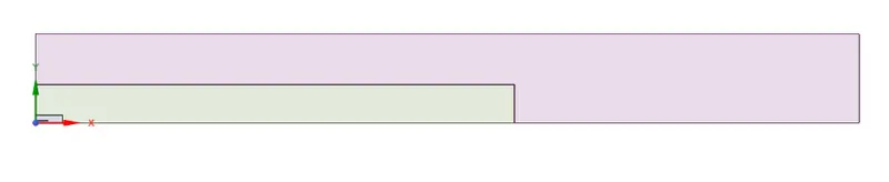
Then 2-D surface is copied to the new sketch plane.
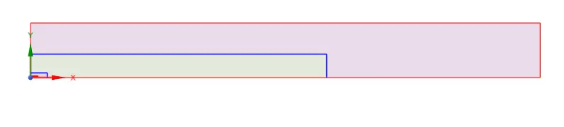
Then share the topology using share topology command which is present under the workbench. In order to mesh interface properly for properly for proper sharing of information.
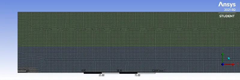
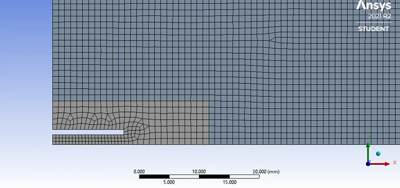
Meshing :
| Element size | 1 mm |
| Capture curvature and proximity | Turned On |
| Mesh method | Quad dominant method |
| No. of nodes | 68647 |
| No. of elements | 67765 |
Enlarged view :
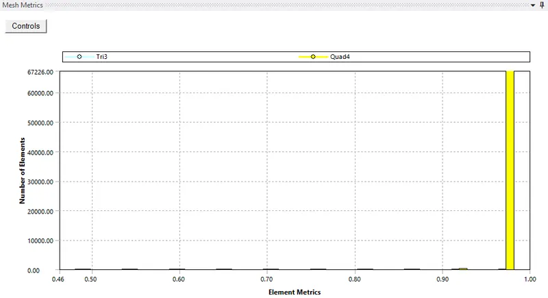
Element statistics :

Element Quality :
Setup :
|
SETUP |
|
|
Solver Type |
Pressure-Based |
|
Velocity Formulation |
Absolute |
|
2D Space |
Axisymmetric |
|
Time |
Steady state |
|
Models |
Viscous model: K-epsilon `->`Standard`->`Standard wall functions Energy model: ON Species: Species transport`->`ON |
|
Material |
Fluid type: Air Solid-type: Aluminium Mixture: Methane-air-2step |
|
Cell zones |
Fluid type: Mixture Solid: Al |
|
Boundaries |
Air-inlet Inlet velocity: 0.5m/s, Temperature = 300k, species`->` `O_2` = 0.21 (molefraction) Fuel-inlet inlet velocity : 80m/s, Temperature = 300k, species`->` `CH_4` and `H_2O`(molefraction) depends upon the case Outlet : pressure-outlet Wall : wall Axis : axis |
|
Reference values |
Standard |
|
Initialization |
Hybrid |
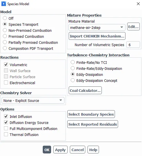
Species model :
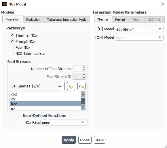
NOx model:
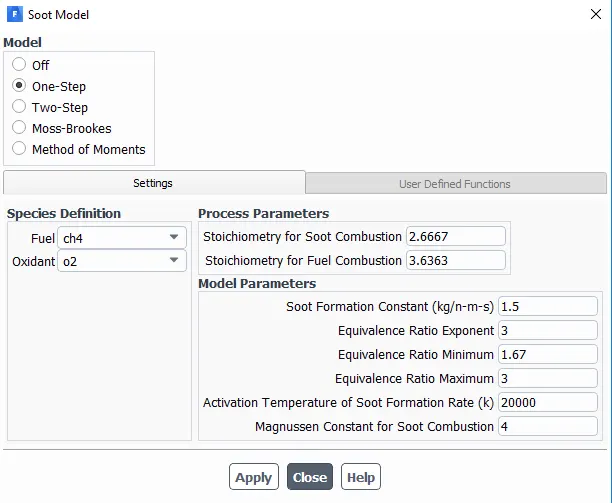
Soot model:
CASES:
1. `CH_4` - mole fraction =1
2.1. `CH_4` - mole fraction =0.90; `H_2O` - mole fraction =0.1
2.2. `CH_4` - mole fraction =0.85; `H_2O` - mole fraction =0.15
2.3. `CH_4` - mole fraction =0.8; `H_2O` - mole fraction =0.2
2.4. `CH_4` - mole fraction =0.75; `H_2O` - mole fraction =0.25
2.5. `CH_4` - mole fraction =0.7; `H_2O` - mole fraction =0.3
Results :
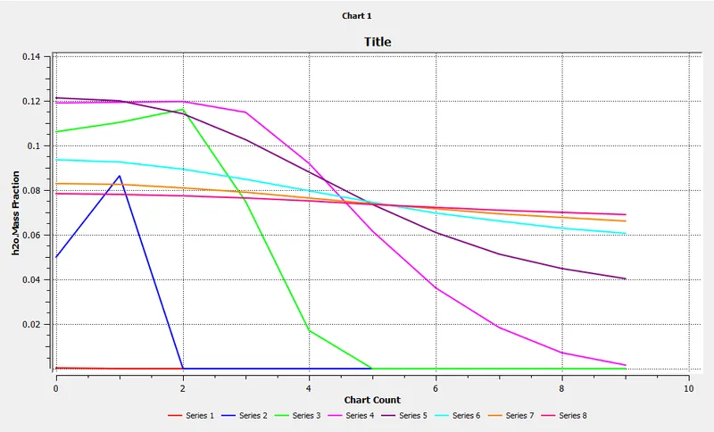
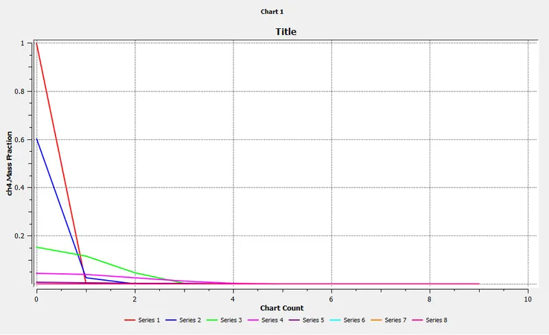
Location of line probes :
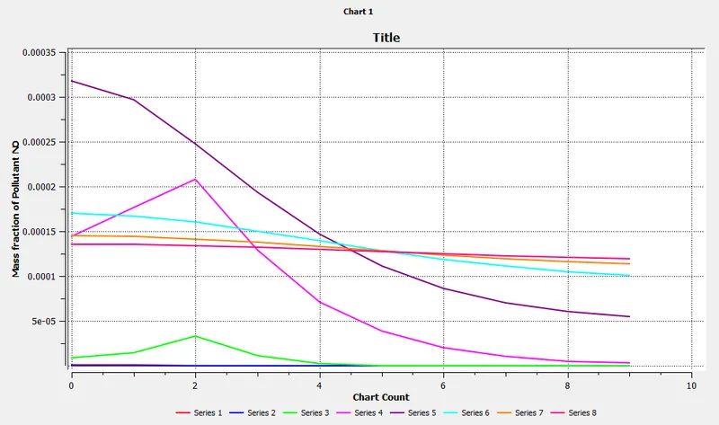
Line 1 :
Point 1-> x=0.015m y=0m z=0m
Point 2-> x=0.015m y=0.0852m z=0m
Line 2 :
Point 1-> x=0.05m y=0m z=0m
Point 2-> x=0.05m y=0.0852m z=0m
Line 3 :
Point 1-> x=0.15m y=0m z=0m
Point 2-> x=0.15m y=0.0852m z=0m
Line 4 :
Point 1-> x=0.3m y=0m z=0m
Point 2-> x=0.3m y=0.0852m z=0m
Line 5 :
Point 1-> x=0.45m y=0m z=0m
Point 2-> x=0.45m y=0.0852m z=0m
Line 6 :
Point 1-> x=0.6m y=0m z=0m
Point 2-> x=0.6m y=0.0852m z=0m
Line 7 :
Point 1-> x=0.7m y=0m z=0m
Point 2-> x=0.7m y=0.0852m z=0m
Line 8 :
Point 1-> x=0.79m y=0m z=0m
Point 2-> x=0.79m y=0.0852m z=0m
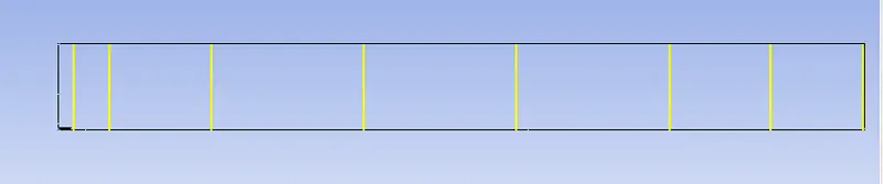
Note : line plots are made at this locations applicable to all cases.
Case I. `CH_4`, mole fraction =1
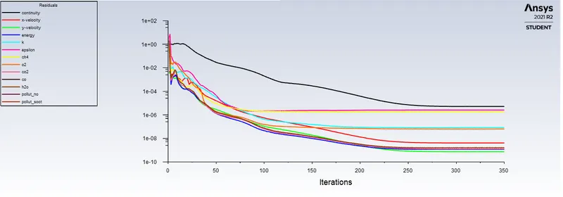
Residual plot :
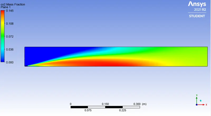
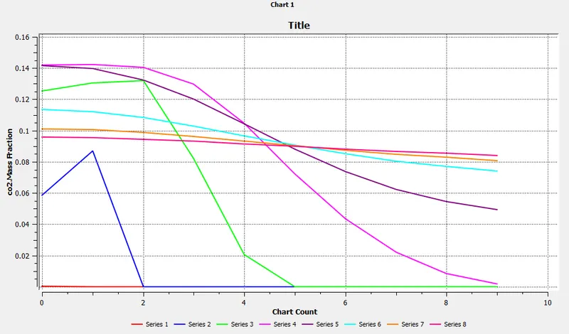
a) Contour and plot of `CO_2` mass fraction :
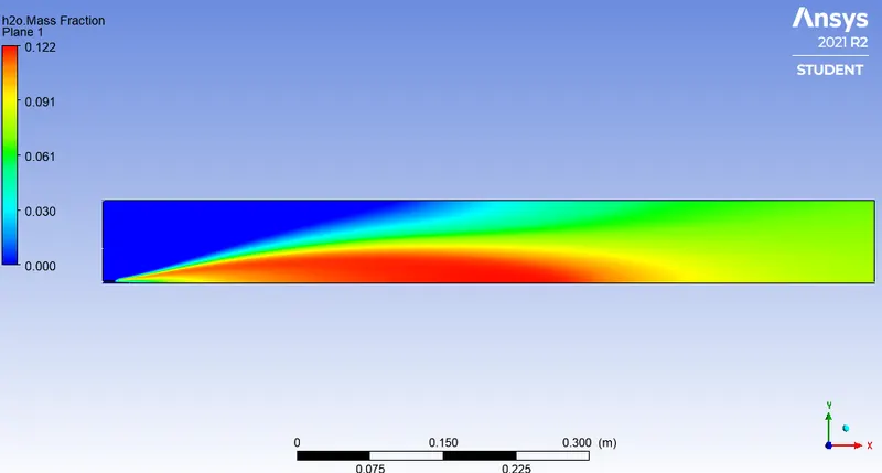
b) Contour and plot of `H_2O` mass fraction :
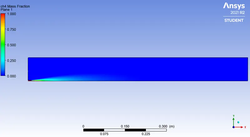
c) Contour and plot of `CH_4` mass fraction :
d) Contour and plot of `N_2` mass fraction :
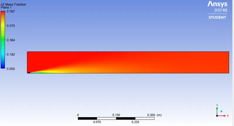
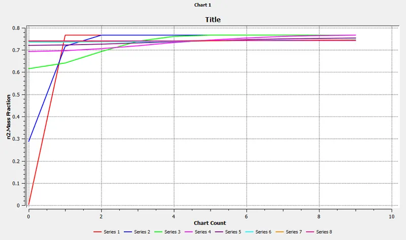
e) Contour and plot of `O_2` mass fraction :
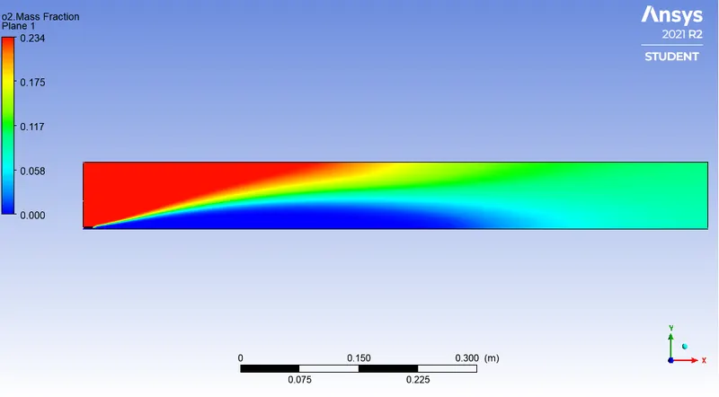
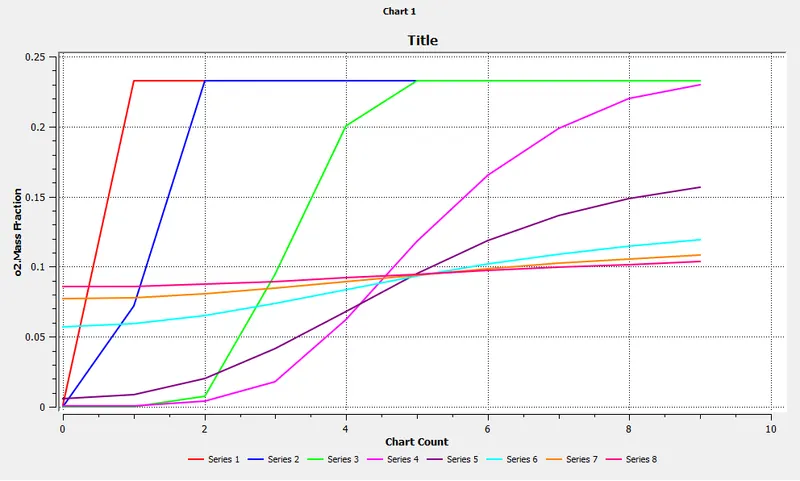
f) Contour and plot of `NO_x` mass fraction :
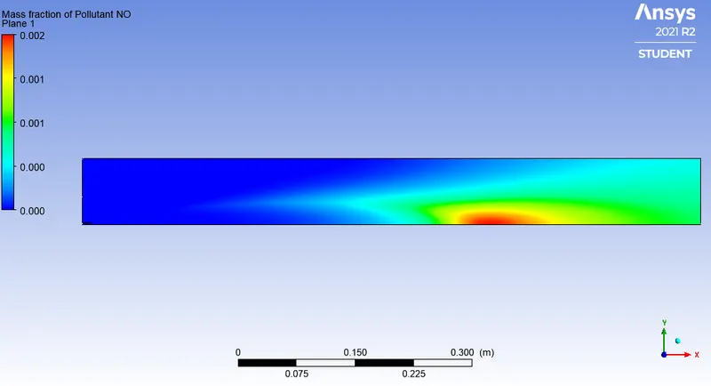
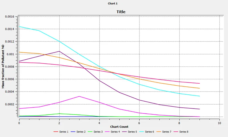
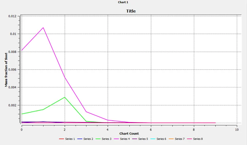
g) Contour and plot of soot mass fraction :
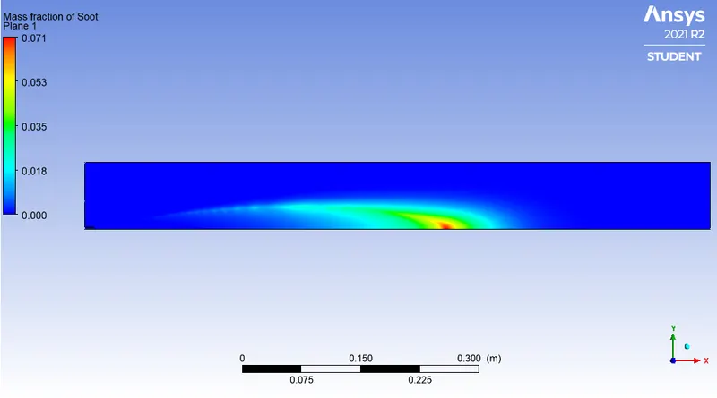
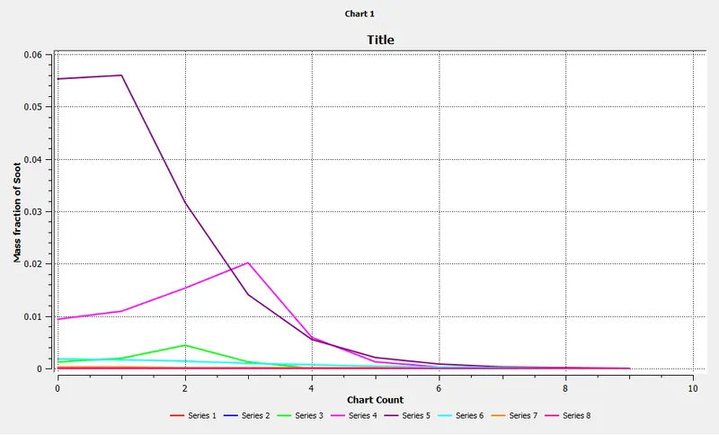
2.1. `CH_4`, mole fraction = 0.90; `H_2O` mole fraction = 0.10
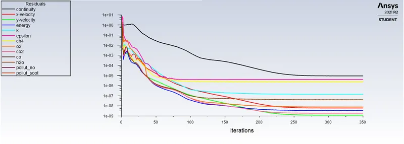
a) Residuals plot :
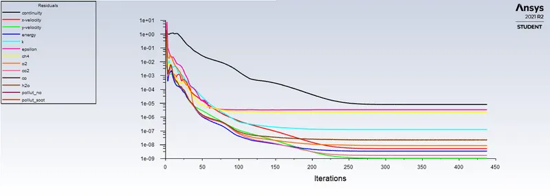
b) Contour and plot of `NO_x` mass fraction :
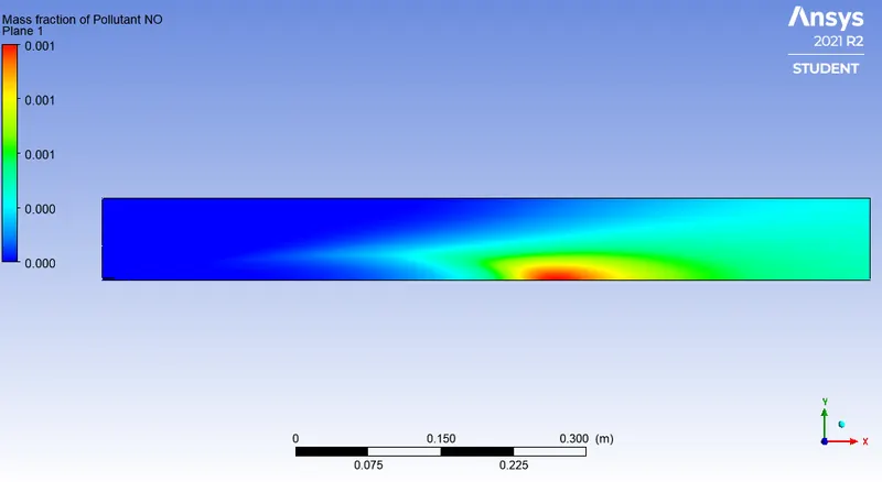
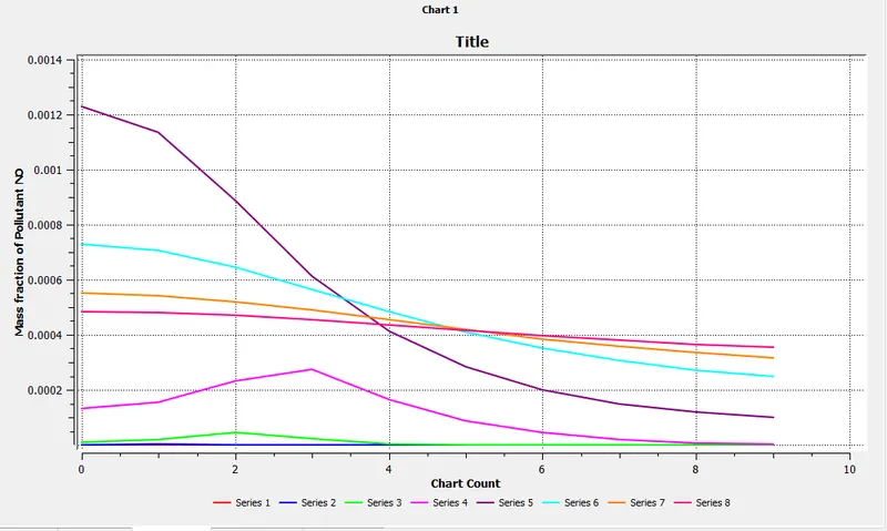
c) Contour and plot of soot mass fraction :
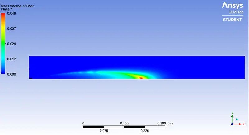
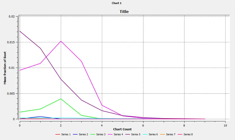
2.2. `CH_4`, mole fraction = 0.85; `H_2O` mole fraction = 0.15
a) Residuals plot :
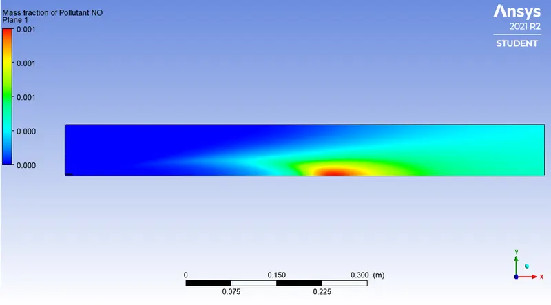
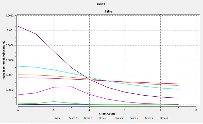
b) Contour and plot of `NO_x` mass fraction :
c) Contour and plot of soot mass fraction :
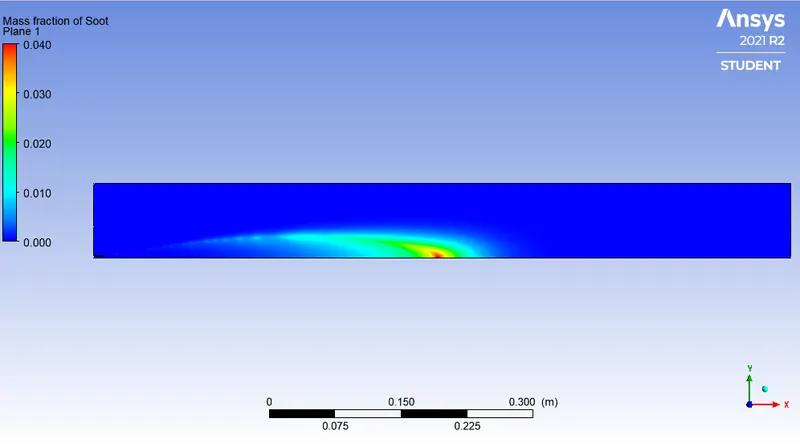
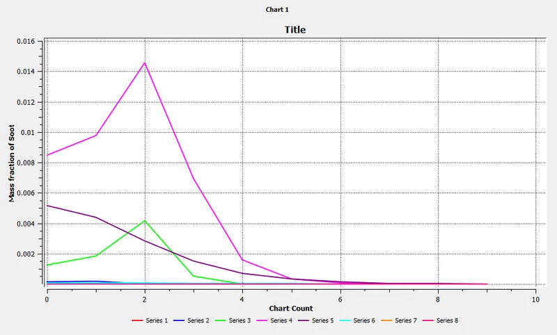
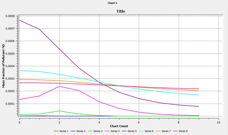
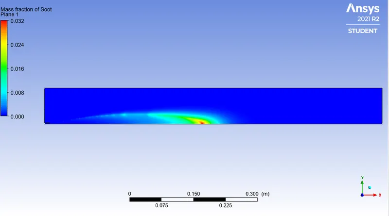
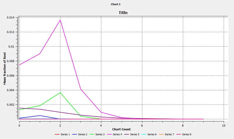
2.3. `CH_4`, mole fraction = 0.80; `H_2O` mole fraction = 0.20
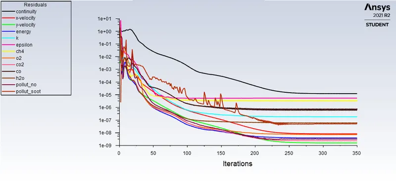
a) Residuals plot :
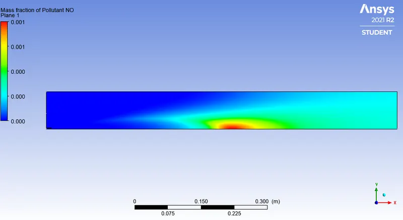
b) Contour and plot of `NO_x` mass fraction :
c) Contour and plot of soot mass fraction :
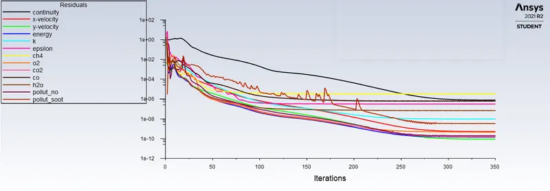
2.4. `CH_4`, mole fraction = 0.75; `H_2O` mole fraction = 0.25
a) Residuals plot :
b) Contour and plot of `NO_x` mass fraction :
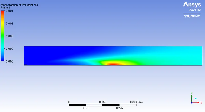
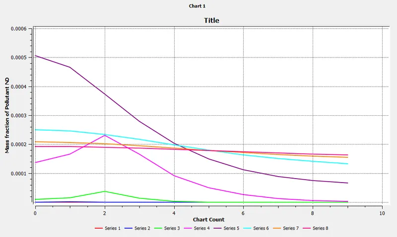
c) Contour and plot of soot mass fraction :
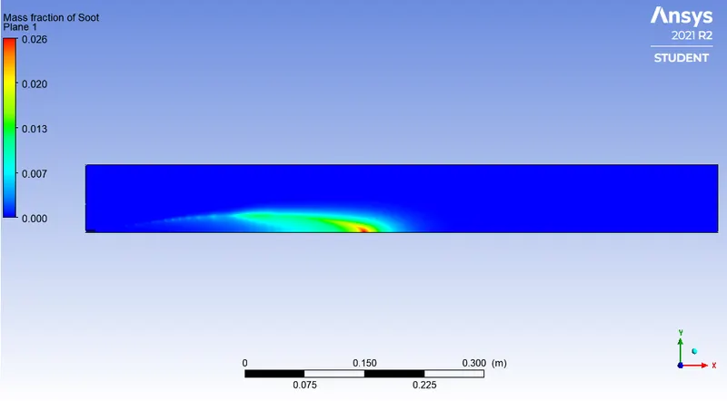
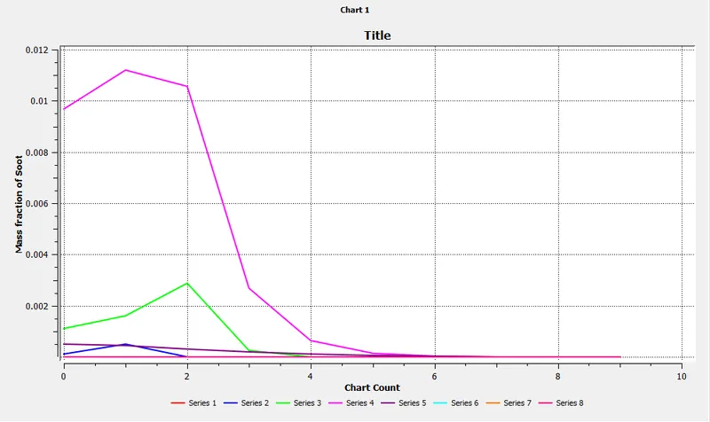
2.5. `CH_4`, mole fraction = 0.70; `H_2O` mole fraction = 0.30
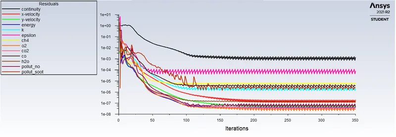
a) Residuals plot :
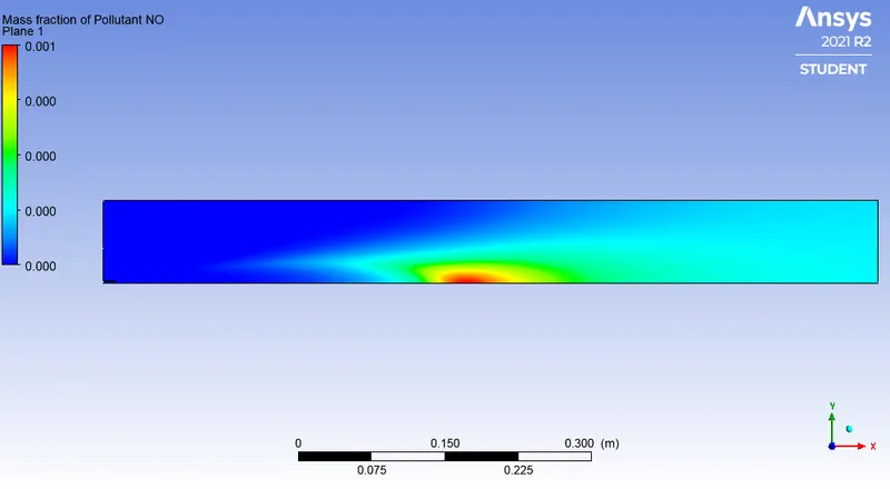
b) Contour and plot of `NO_x` mass fraction :
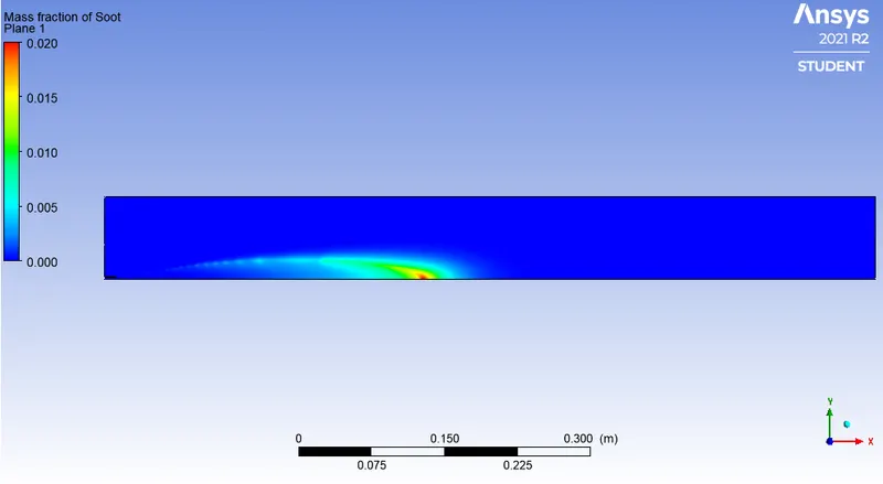
c) Contour and plot of soot mass fraction :
|
`CH_4` (Mole fraction) |
`H_2O` (mole fraction) |
Area weighted average mass fraction of `NO_x` at outlet | Area weighted average mass fraction of soot at outlet |
| 1 | 0 | 1.7954714e-05 | 0.00064415665 |
| 0.9 | 0.1 | 2.1252109e-06 | 0.00039956801 |
| 0.85 | 0.15 | 7.0659856e-07 | 0.00030945924 |
| 0.8 | 0.2 | 2.1818396e-07 | 0.00023486823 |
| 0.75 | 0.25 | 6.935169e-08 | 0.00017418955 |
| 0.7 | 0.3 | 1.7268942e-08 | 0.00012537126 |
Conclusion :
- Diluting fuel with H2O does indeed reduce the formation of harmful pollutants such as NOx and soot at the outlet.
- The rate of reduction in the concentration of soot is greater than that of NOx when diluting the fuel.
- Fuel dilution by H2O is a great way to reduce emissions. However, a trade-off must be made between the performance required and the dilution amount.
- Since soot value decreases with dilution we can say there is less wastage of fuel, i.e. complete combustion occurs.
- Eddy - dissipation model(Turbulence Chemistry Interaction) helps us to model combustion via turbulence mixing without the presence of an ignition source.
References :
https://cfdflowengineering.com/cfd-modeling-pollutants-nox-sox-and-soot/#Thermal_NOx