Week 10: Project 1 - FULL HYDRO case set up (PFI)
Aim- To con duct the full hydro set up for pfi angine and to calculate the engine charactersticts.
Objectives-1.Identify thye compression ratio
2.Identify the combustion efficiency
3.Dretemine powe and Torque.
set up
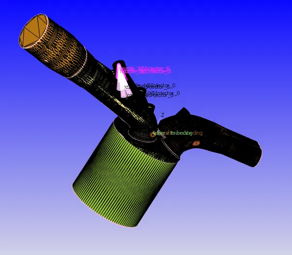
Geometry-
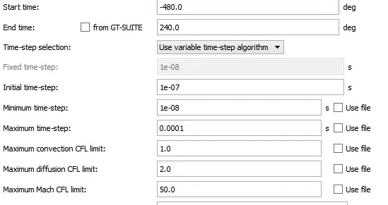
simulation time parameters-
Boundary condtion
- Piston temperature - 450K
- Liner temperature - 450K
- Head temperature - 450K
- Spark Plug temperature - 550K
- Spark Plug electrode temperature - 600K
- Exhaust ports temperature - 500K
- Exhaut outflow - 1 bar
- Exhaust outlflow temperature - 800k
- Exhaust species concentration - Calculate the stoichiometric condition
- Exhaust valve top temperature - 525K
- Exhaust valve angle temperature - 525K
- Exhaust valve bottom temeprature - 525K
- Intake port - 1 temperature 425K
- Intake port - 2 temperature 425K
- Inflow pressure - 1 bar total pressure
- Inflow temperature - 363K
- Inflow species - Air
- Intake valve top temperature - 480K
- Intake valve angle temperature - 480K
- Intake valve bottom temeprature - 480K
Initial conditions
- Intake port - 1 (closer to combustion chamber)
- ic8h18 - 0.025508
- o2 - 0.20157
- n2 - 0.77292
- Temperature - 390k
- pressure - 1 bar
- Intake port - 2 (away from combustion chamber)
- Air
- Temperature - 370K
- Pressure - 1 bar
- Cylinder
- Pressure - 1.85731 bar
- Temperature - 1360K
- Stoichiometric composition
Injection Parameters
- Fuel flow rate = 7.5e-4 Kg/second
- Injection start time = -480.0
- Injection duration = 191.2
- Fuel temperature = 330K
Nozzle positions
Nozzle diameter = 250 micro-meter
Circular injection radius = Nozzle radius
Spray cone angle = 10
- Nozzle 0
- center 0.0823357 0.00100001 0.07019
- Align Vector -0.732501 0.210489 -0.647408
- Nozzle 1
- center 0.0823357 -0.00099999 0.07019
- Align Vector -0.732501 -0.210489 -0.647408
- Nozzle 2
- center 0.0823357 -0.0004 0.07019
- Align Vector -0.5 -0.2 -0.647408
- Nozzle 3
- center 0.0823357 0.0003 0.07019
- Align Vector -0.5 0.2 -0.647408
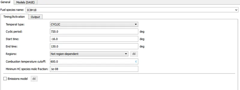
Spark Ignition Parameters
- Start of spark = -15 deg
- Spark duration = 10 deg
- Spark location = -0.003 0 0.0091
- Spark radius = 0.0005m
Turblence Model-Defalut Kpsilon RNG model ued as this is recommended for combustion in converge.
Mesh
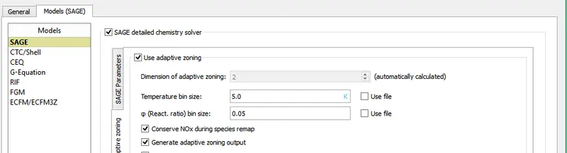
Grid size of 0.004 was used in all the direction and advap-tive Mesh refinemewnt was used for the cyclinder and the portion of the intake near the cyclinder .The Amr was definedsensitive to velovity and temperature
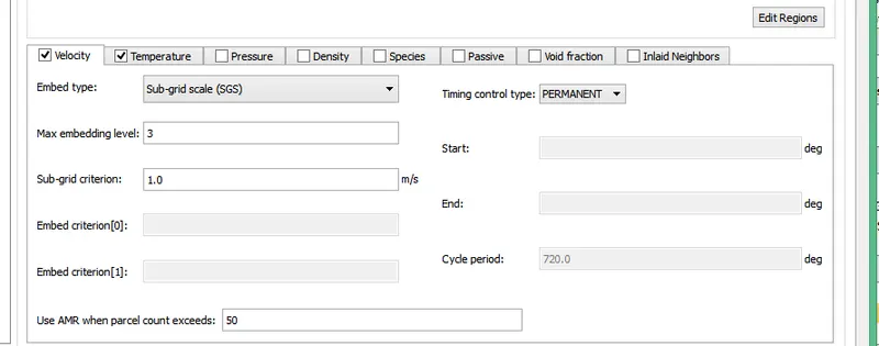
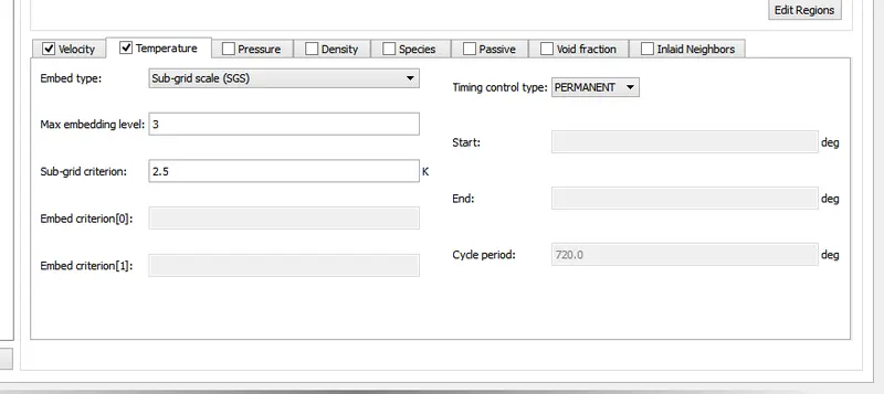
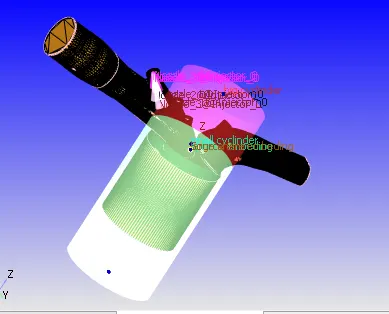
Fixed embeding was aslo done in the following regions
Results
compression ratio-The compression ratio is defined as the ratio between the volume of the cylinder with the piston in the bottom position, Vbottom (largest volume), and in the top position, Vtop (smallest volume).
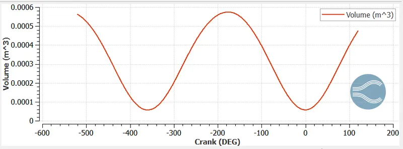
from above plot the minimimum volume is 5.70326e-5 and the maximum volume is 0.000574187
and the compression ratio is=(5.74187e-5)/(5.70326e-5)=10.06
Hence compression ratio is 10:1
Combustion effiency-the formula to calculate the efficiency is
Efficiency=(Total engery from the combustion process)/(Engery content)
the numertor from above euation is the maximium value of the integrated HR curve as shown below
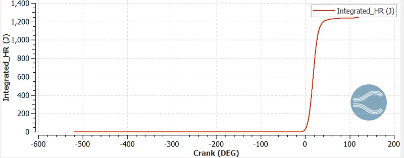
Engery content of the fuel =Mass of the fuel *Lower heating value of IC8H18
mass of the fuel=44.8MJ/kg
LHV of IC8H18=3e-5
therefore efficiency=((12411/(44.8*3e-5))=92.4%
Why do we need a wall heat transfer model? Why can't we predict the wall temperature from the CFD simulation?
In PFI engine the compressed air and the fuel is ignited by the spark plug which results flame propgation inside the cyclinder as flame propagetes the effiency ,power and the emission are effected hence the the heat from the cyclinder transfered to liner (wall )when it comes to contact with liner hence after some time the spread of the flame stops.Due to the turblance the parameters are effectedhence de to these we use the heat transfer model.
What is the significance of ca10, ca50 and ca90?
The ca10 indiactes the combustion process at crank angle of 10 the significance it indiactesthe start of the combustion and the ca50 indicates the combution process at the crank angle of 50 and its significance is it defines the premixed combustion AND THE START OF THE DIFFUSION combustion of the fuel. and the ca90 indicates the combustion process at the crank angle of 90 and it indicated the end of combustion process.
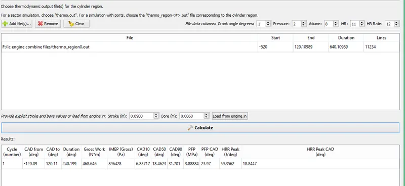
from the engine performance calculator
WD=486.646N-M
combustion duration=240.199degg
crank nspeed=3000rpm
number of degress per second=18000
time for one degree=5.5555e-05
Time taken for combustion=5.555e-05*240.199=0.01334 sec
power=work done/time taken for combustion
=486.646/0.01334=35.13KW
Torque=power*60/pi*N
=35160*60/2*pi*3000=111.822N-m
https://youtu.be/DwQHLfzGstc
sa