Week 10: Project 1 - FULL HYDRO case set up (PFI)
AIM:
To do a full hydrodynamic simulation of port fuel injection and post process the results.
OBJECTIVE:
- Import the CAD model of IC engine into converge and run diagnosis.
- Setup the case for hydrodynamic simulation and to create animation in paraview.
INTRODUCTION:
GEOMETRY SETUP:
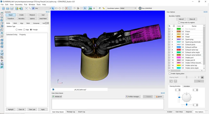
- IMPORT GEOMETRY:
Geometry that is provided .stl is imported to the workspace.
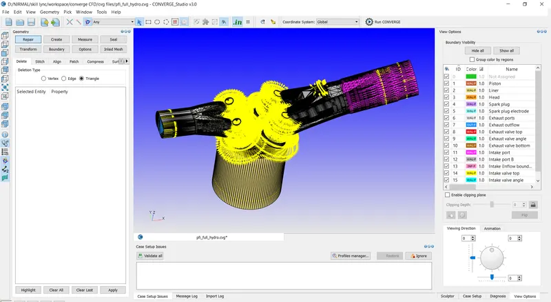
- NORMAL ORIENTATION:
The orientation of normal are checked and its changed such that the normal points inwards by going to transform > normal
- CREATING BOUNDARIES:
The boundary are created for the geometry under boundary flag tab.
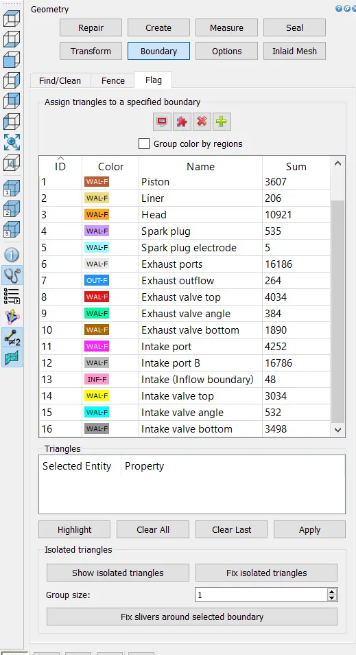
The boundaries are assigned to the faces and the name of the boundaries are edited and click apply.
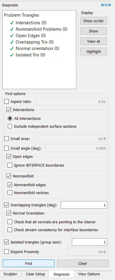
- DIAGNOSIS:
The diagnosis is runed and checked for problems for the geometry.
BEGIN CASE SETUP:
- APPLICATION TYPE:
On the right panel go to the case setup tab, select begin case setup.
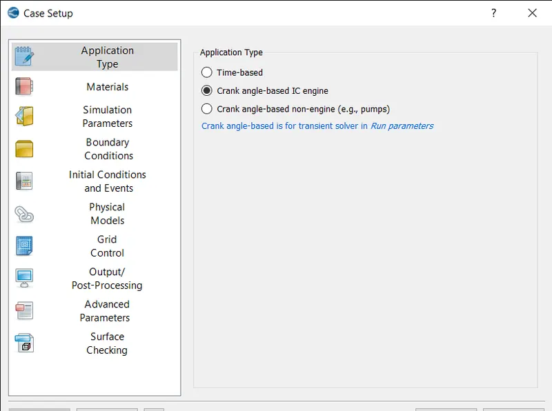
Select the application type as crank angle based ic engine and select apply and done.
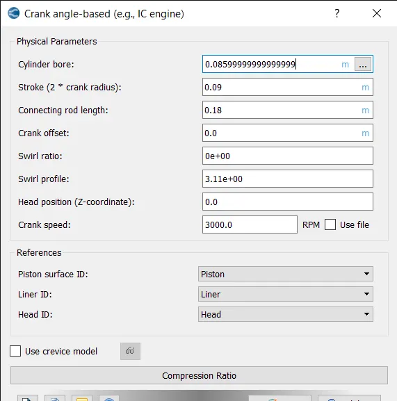
The physical parameters are applied.
- MATERIALS:
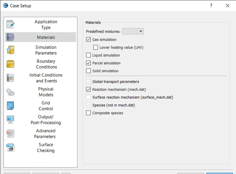
Select materials and select the checkbox reaction mechanism and parcel simulation then click apply and done.
- GAS SIMULATION:
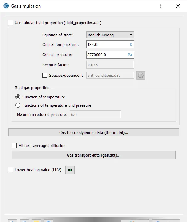
The default values are selected and press ok.
- PARCEL SIMULATION:
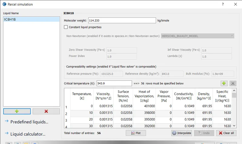
The IC8H18 liquid is selected from the predefined liquid list.
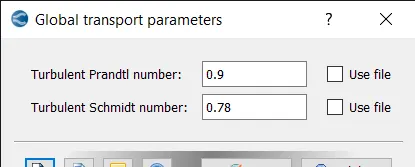
- GLOBAL TRANSPORT PROPERTIES:
Select global transport properties, keep the default values and press ok.
- REACTION MECHANISM:
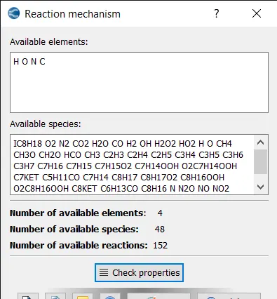
The species are added and checked the properties and click apply.
- SPECIES:
PARCEL SPECIES:
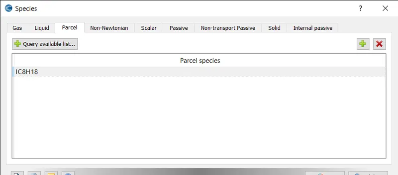
Under parcel tab add IC8H18 from the query available list.
PASSIVE SPECIES:
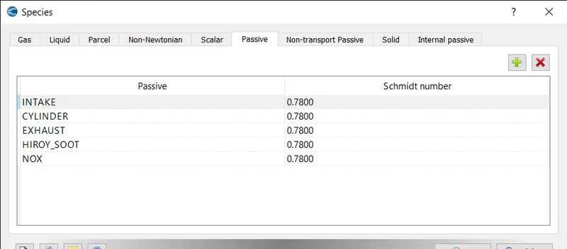
In passive add the above passives as shown above.
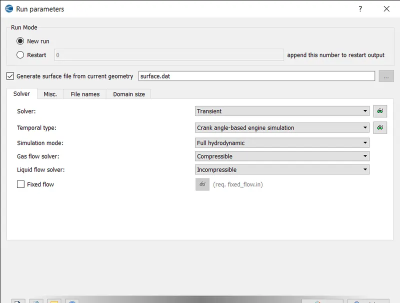
- RUN PARAMETERS:
Under solver tab select solver as transient solver.
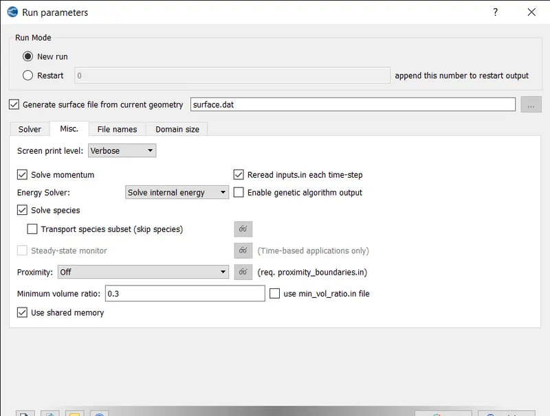
- MISC TAB:
Under misc tab uncheck use shared memory option and click ok.
- SIMULATION TIME PARAMETERS:
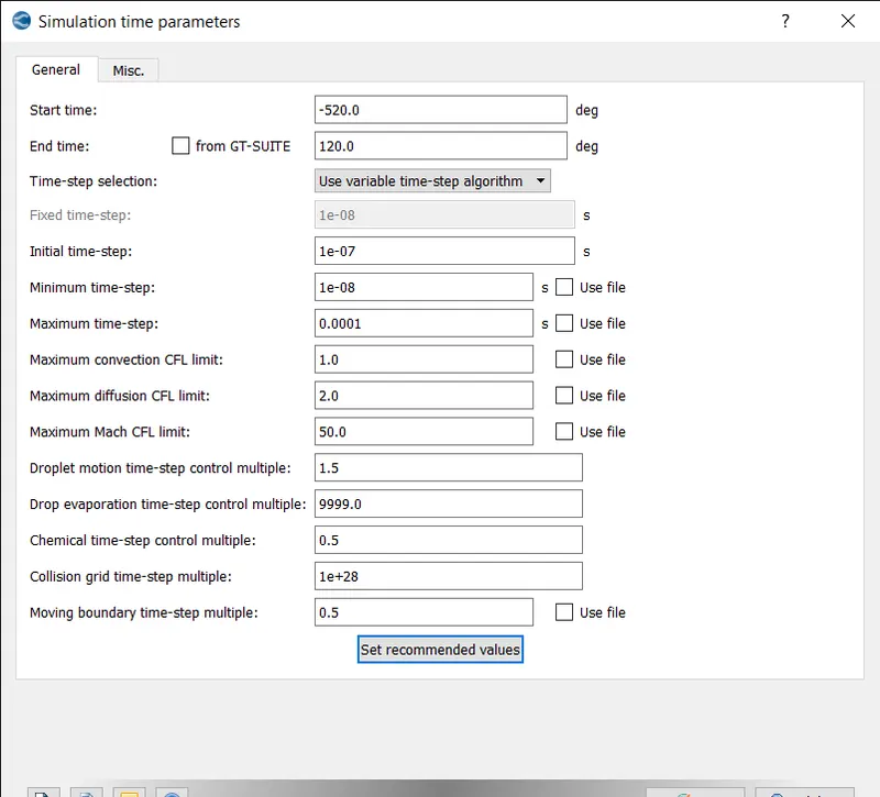
Set the start time, end time, initial, minimum and maximum time steps as shown above.
- SOLVER PARAMETERS:
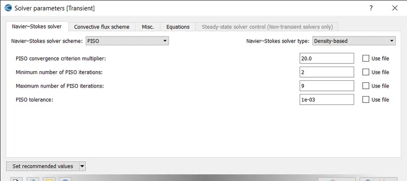
Select the Navier-stokes solver type as density based and click ok.
- REGIONS AND INITIALIZATIONS:
CYLINDER REGION:
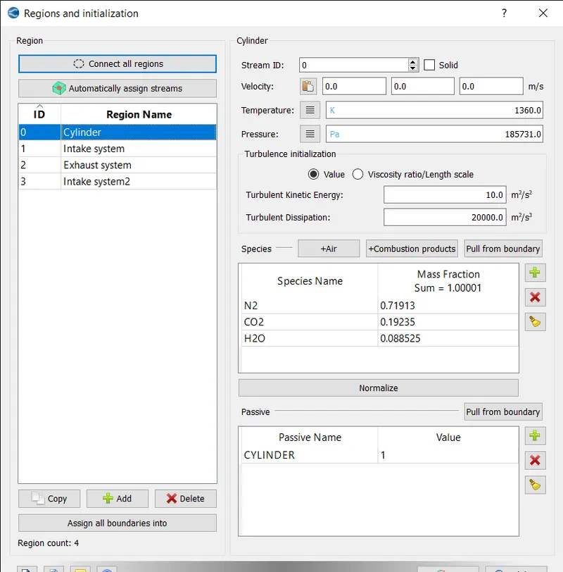
The cylinder region is created and the species co2, h2o and n2 is added.
INTAKE PORT 1 REGION:
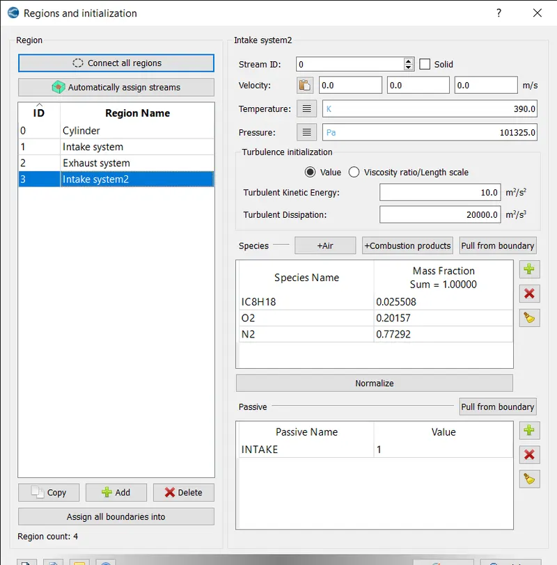
In the intake port 1 region the temperature is set to 390k and pressure as atmospheric pressure and ic8h18, o2 and n2 are added as species.
INTAKE PORT 2 REGION:
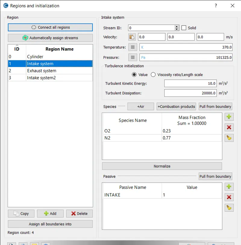
in this region temperature is set to 370 k and pressure as atm and air is added as species.
EXHAUST REGION:
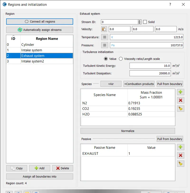
In this region temperature is set to 1215k and temperature as 1037371pa and co2 , h2o and n2 are added as species.
- BOUNDARY CONDITIONS:
PISTON BOUNDARY:
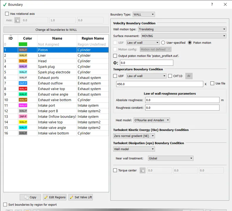
The boundary type is set to wall and motion as translating and movement as moving and temperature b.c. law of wall of 450k is assigned.
LINER:
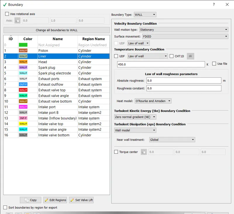
The boundary type is set to wall and motion as stationary and movement as fixed and temperature b.c. law of wall of 450k is assigned.
INFLOW:
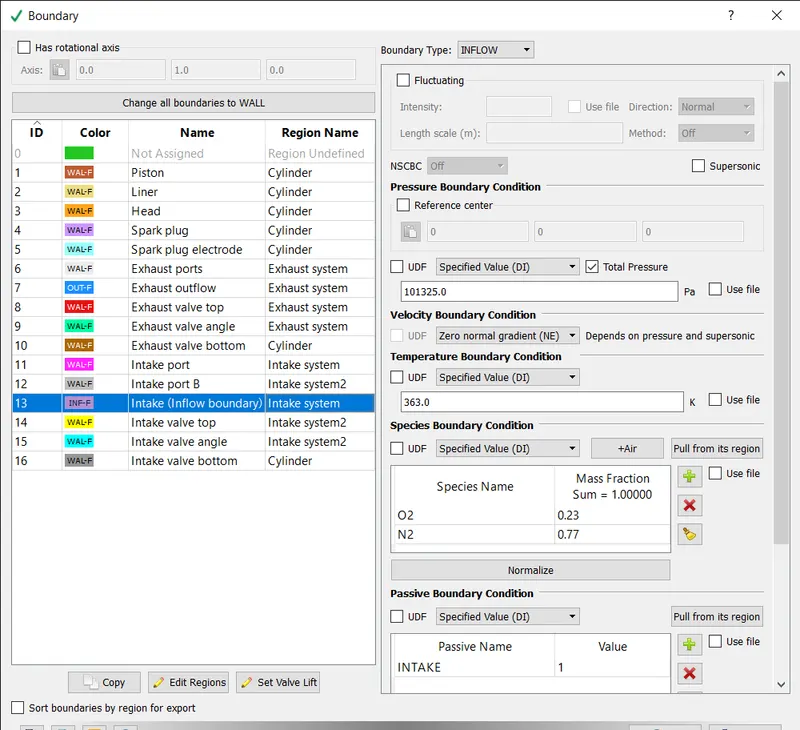
The boundary type is set to inflow and pressure b.c as 101325pa and temperature b.c. as 363k and air is added as species.
CYLINDER HEAD:
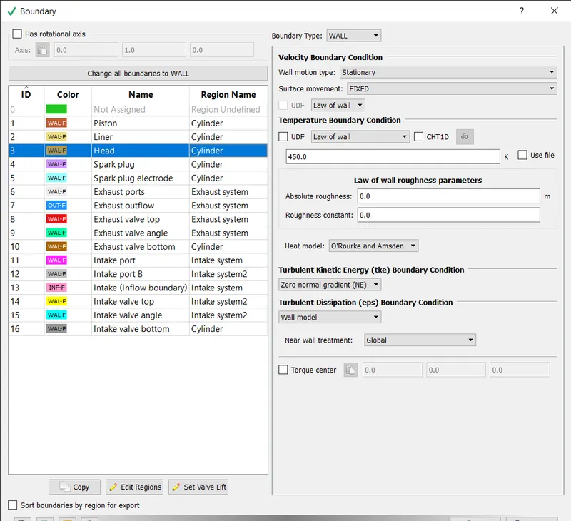
The boundary type is set to wall and motion as stationary and movement as fixed and temperature b.c. law of wall of 450k is assigned.
EXHAUST PORT:
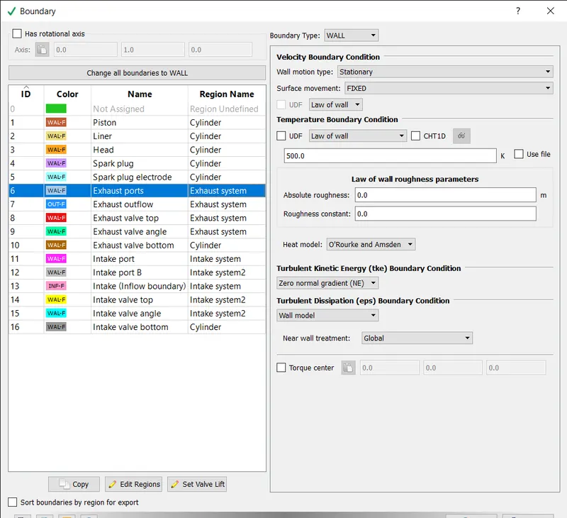
The boundary type is set to wall and motion as stationary and movement as fixed and temperature b.c. law of wall of 500k is assigned.
OUTFLOW:
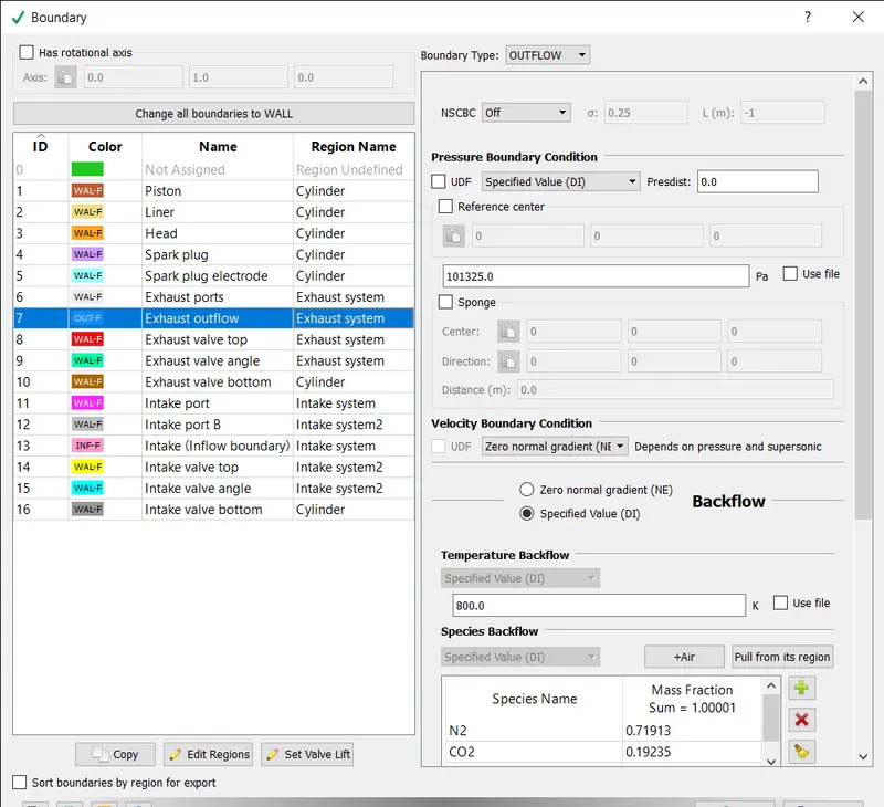
The boundary type is set to outflow and pressure b.c. as atm pressure and temperature b.c. law of wall of 800k is assigned and species backflow is pulled from its region.
EXHAUST VALVE TOP:
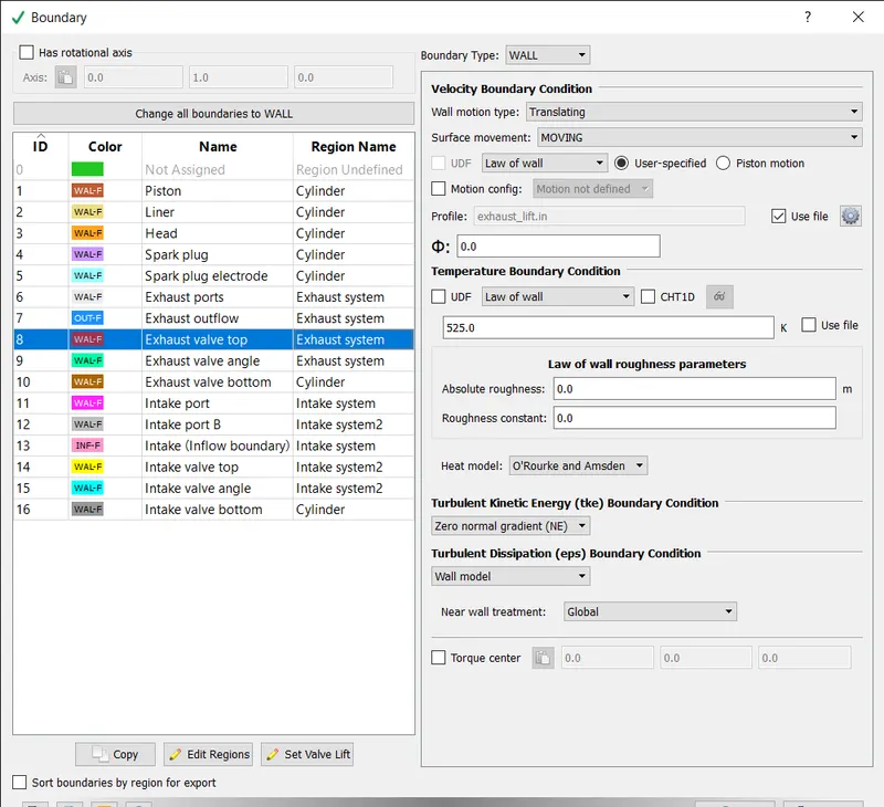
The boundary type is set to wall and motion as translating and movement as moving and temperature b.c. law of wall of 525k is assigned. For profile the exhaust_lift.in file is imported.
EXHAUST VALVE ANGLE:
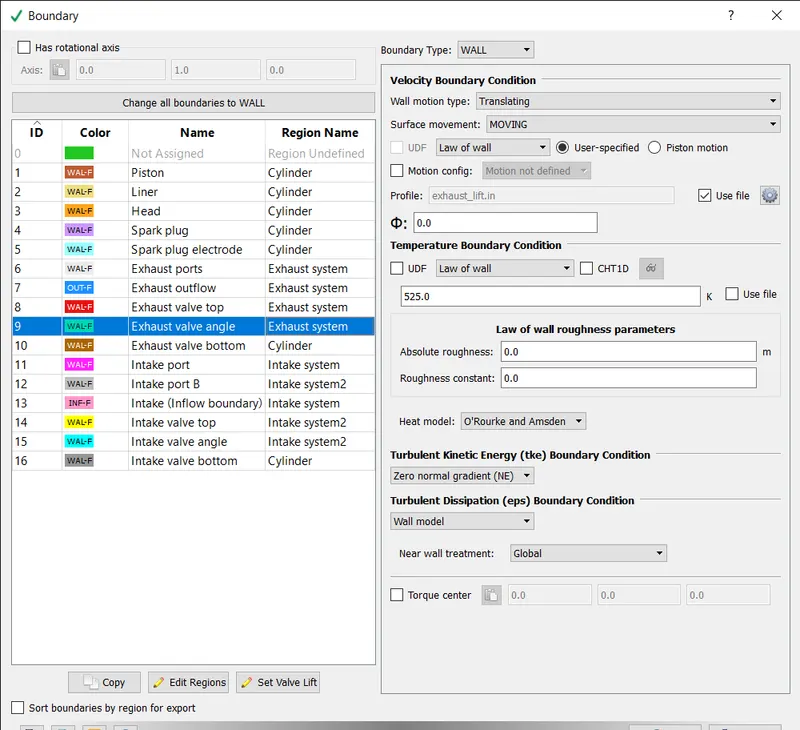
The boundary type is set to wall and motion as translating and movement as moving and temperature b.c. law of wall of 525k is assigned. For profile the exhaust_lift.in file is imported.
EXHAUST VALVE BOTTOM:
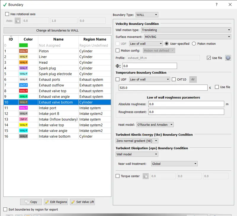
The boundary type is set to wall and motion as translating and movement as moving and temperature b.c. law of wall of 525k is assigned. For profile the exhaust_lift.in file is imported.
INTAKE PORT 1:
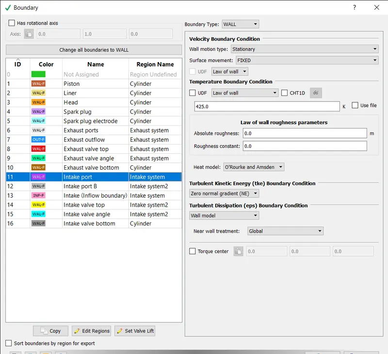
The boundary type is set to wall and stationary as translating and movement as fixed and temperature b.c. law of wall of 425k is assigned.
INTAKE VALVE BOTTOM:
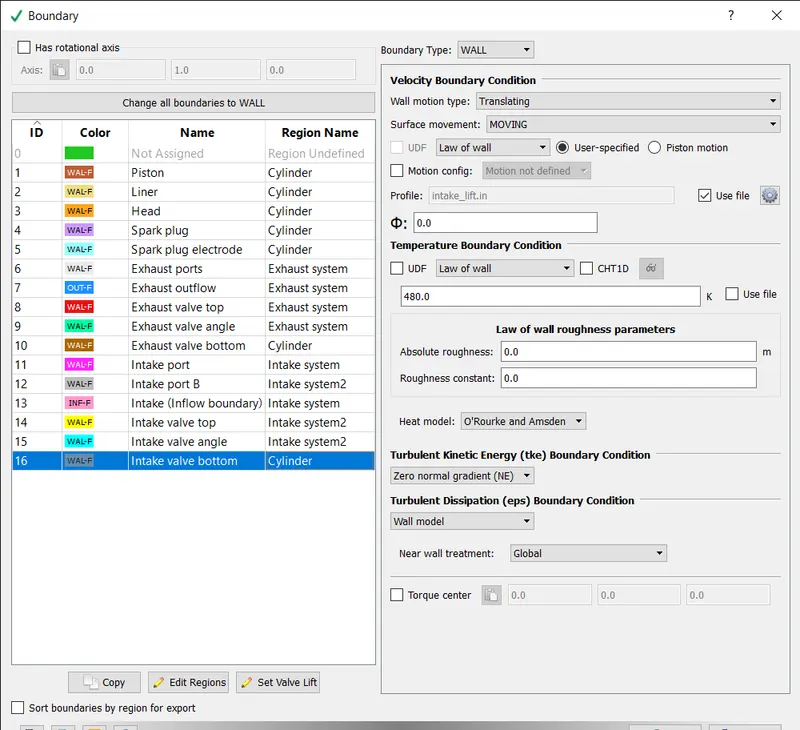
The boundary type is set to wall and motion as translating and movement as moving and temperature b.c. law of wall of 480k is assigned. For profile the intake_lift.in file is imported.
INTAKE VALVE ANGLE:
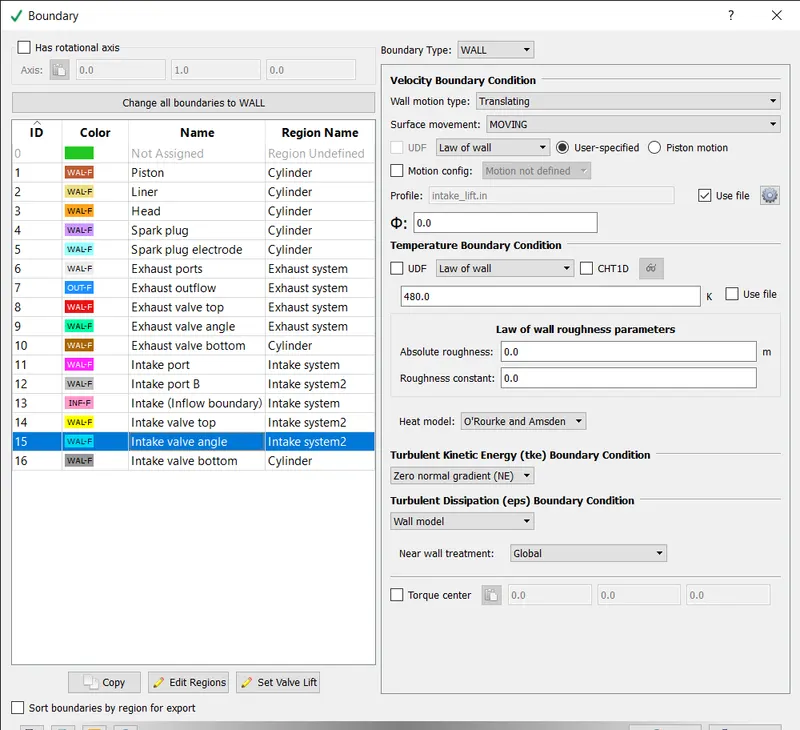
The boundary type is set to wall and motion as translating and movement as moving and temperature b.c. law of wall of 480k is assigned. For profile the intake_lift.in file is imported.
INTAKE VALVE TOP:
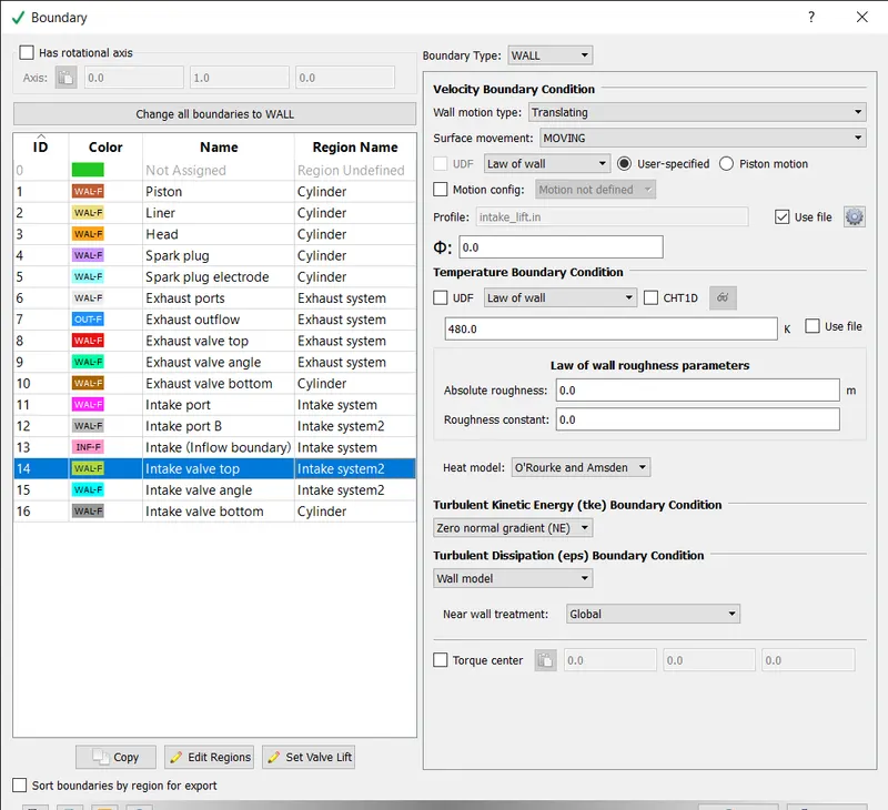
The boundary type is set to wall and motion as translating and movement as moving and temperature b.c. law of wall of 480k is assigned. For profile the intake_lift.in file is imported.
SPARK PLUG TERMINAL:
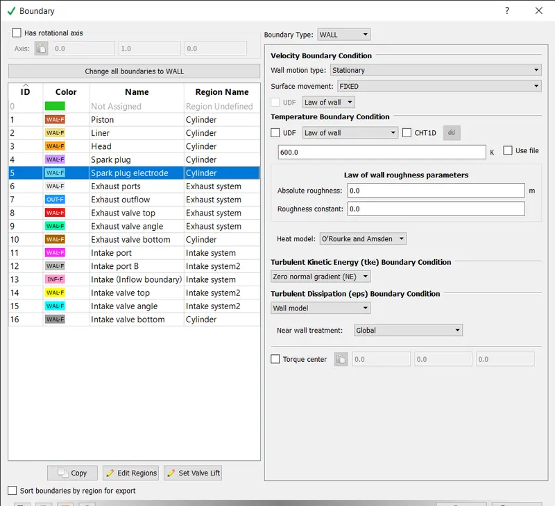
The boundary type is set to wall and motion as stationary and movement as fixed and temperature b.c. law of wall of 600k is assigned.
SPARK PLUG:
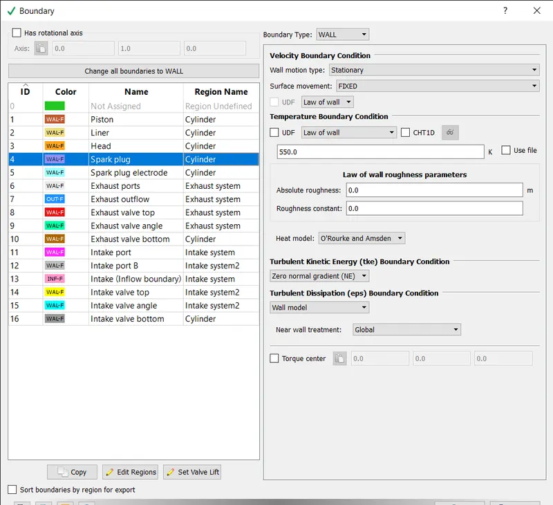
The boundary type is set to wall and motion as stationary and movement as fixed and temperature b.c. law of wall of 550k is assigned.
INTAKE PORT 2:
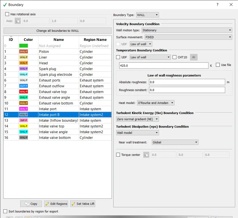
The boundary type is set to wall and motion as stationary and movement as fixed and temperature b.c. law of wall of 425k is assigned.
- EVENTS:
CYCLIC EVENT:
The cyclic event is created between cylinder region and intake port 1 and exhaust region and assigned the event as valve.
The permanent event is created between intake port 1 and intake port 2 and keep the event as open.
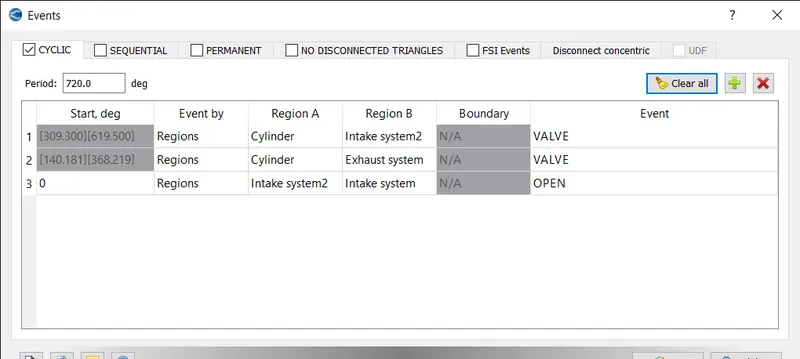
After turning on the events flag, the event can be set by selecting the events option in the case set-up tree.
Events can be cyclic, permanent or sequential.
Based on how the event should occur, the type of event can be chosen from the options available.
The event can repeat itself over cycles, in a sequence or can be set permanently. Based on this setting, Converge creates what is called as disconnected triangles. These are triangles that Converge creates and do not show up in post processing as they are temporarily created for the purpose of simulating the event.
Triangles are created for when there should be no interaction between the 2 regions and these triangles are deactivated when there is supposed to be an interaction between the 2 regions. It is important to note that no triangles must be created by the user, only events must be defined in order to have no intersecting triangles.
- GROUP COLOUR BY REGION:
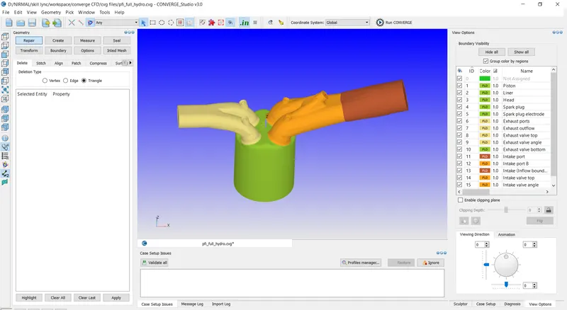
when the group color by region is selected the model is grouped by regions.
- PHYSICAL MODEL:
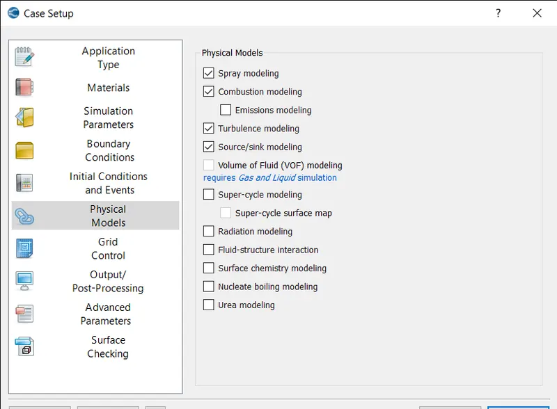
In physical models the sparay modelling, combustion modelling, turbulence modelling and source/sink modelling is added.
- SPRAY MODELLING;
DROP EVAPORATION:
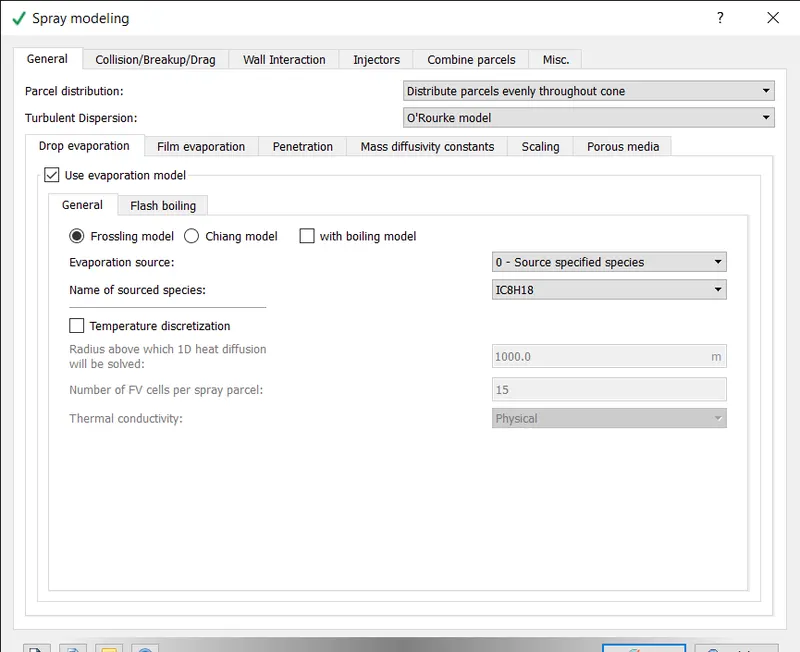
The o'Rourke model is added as turbulent dispersion.
COLLISION:
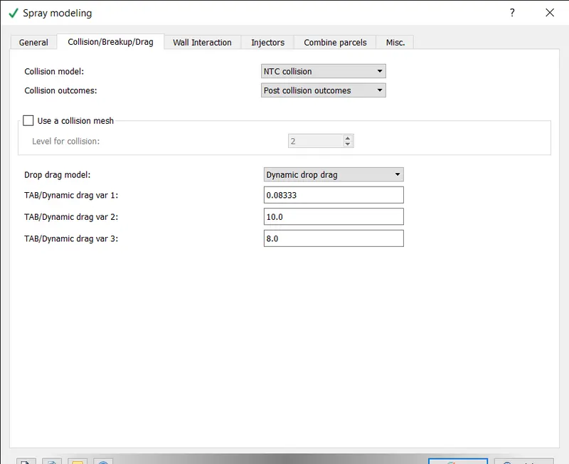
The NTC collision is selected as collision model and dynamic drop drag is added as drop drag model.
WALL INTERACTION:
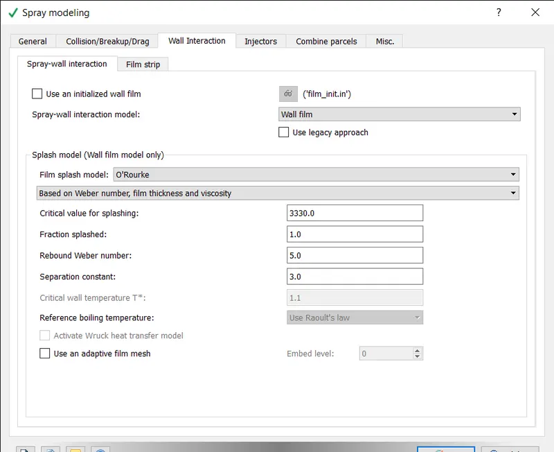
select the wall flim as spray wall interaction model and o'Rourke as flim splash model.
INJECTOR:
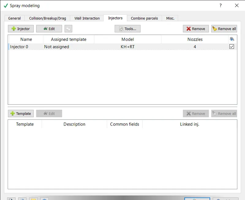
RATE SHAPE:
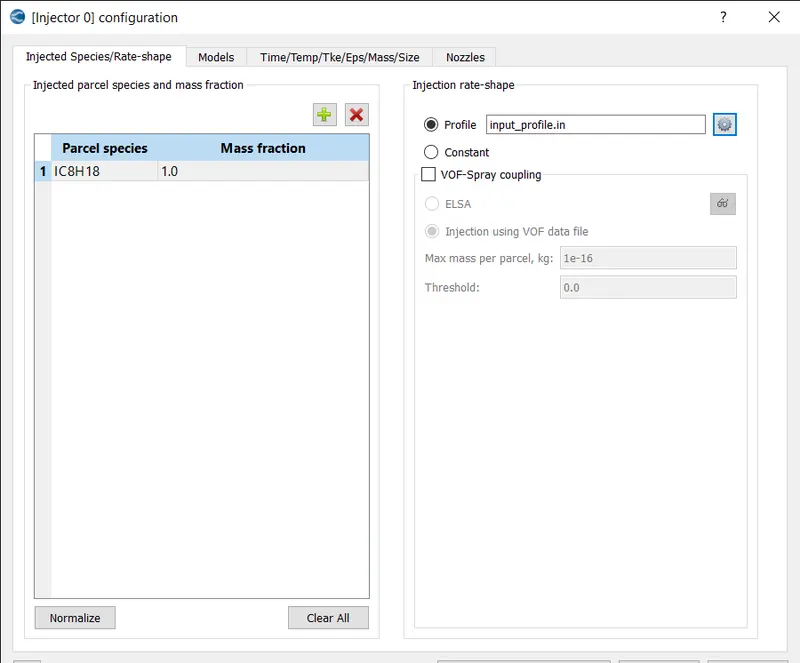
IC8H18 is added as parcel species.
MODELS:
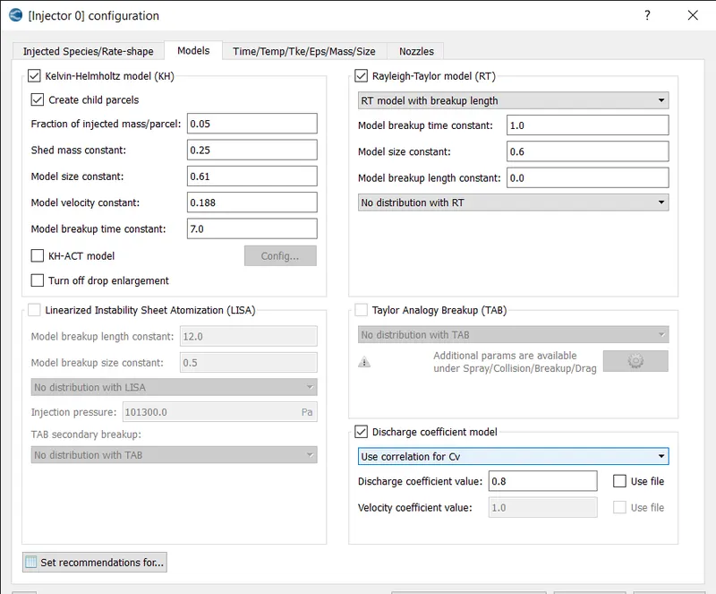
KH and RT models are added and dischargr coefficient value is given 0.8.
TIME/TEMP/TKE/MASS/SIZE:
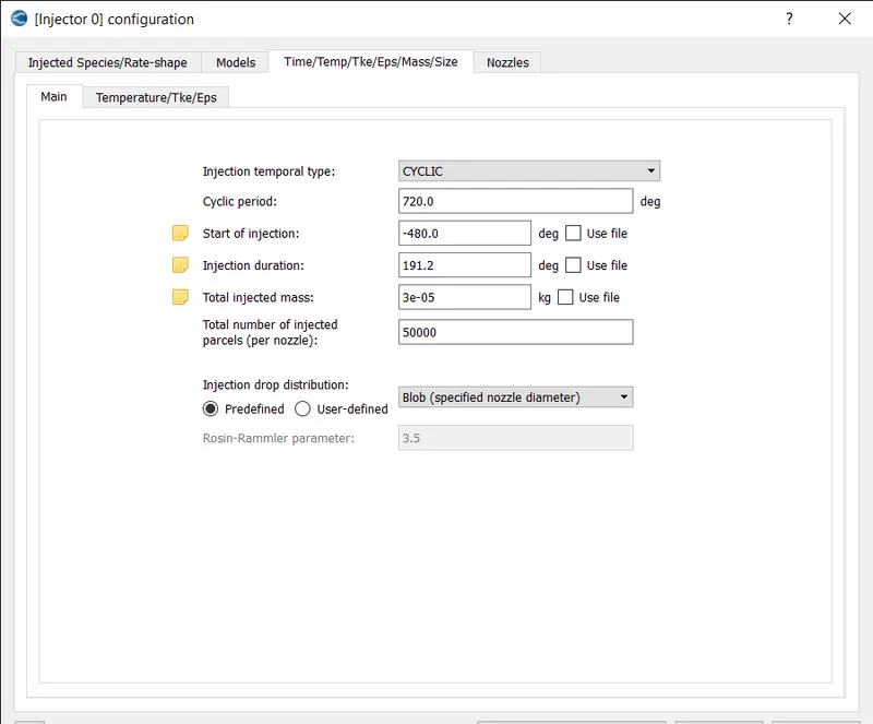
A injection type is cyclic and injection drop distribution as blob.
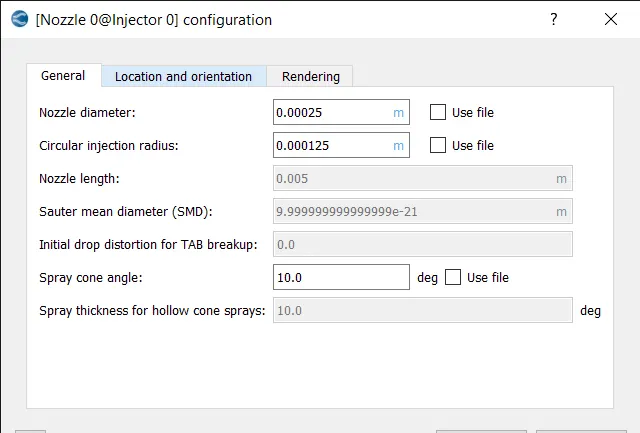
NOZZLES:
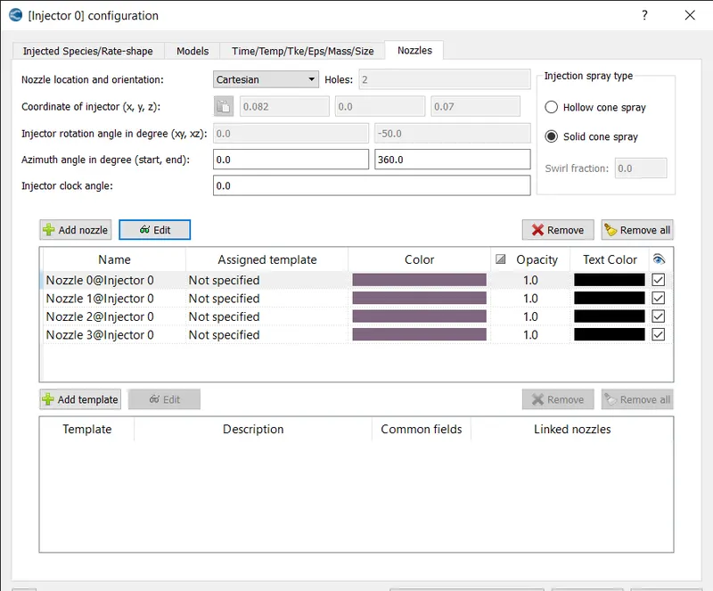
LOCATION:
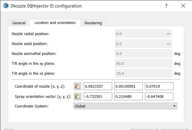
The nozzle location and nozzle diameter and injection radius are defined.
similarly, the nozzle is defined for other three nozzles.
COMBUSTION MODELLING:
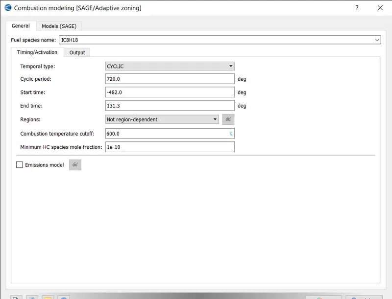
The general parameters to define combustion model are specified.
MODELS:
SAGE PARAMETERS:
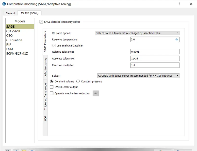
SAGE is added as combustion model and values are seted as default.
ADAPTIVE ZONING:
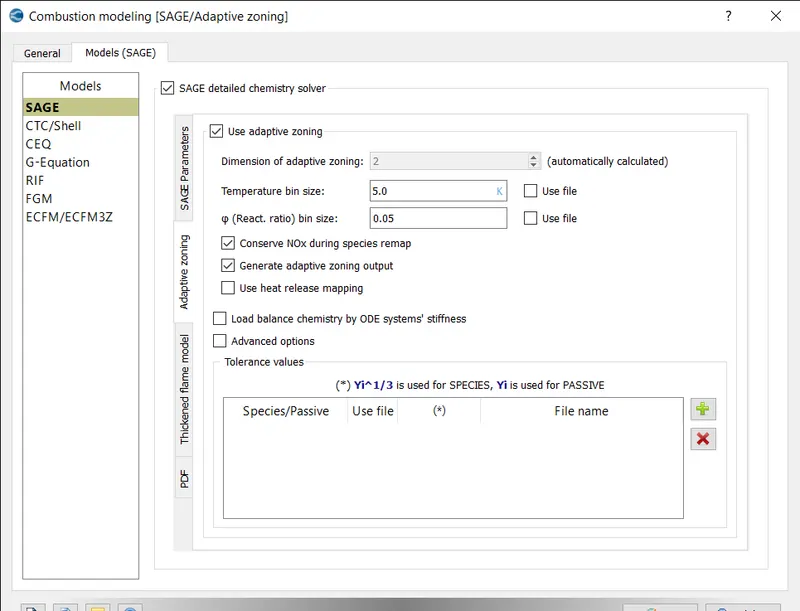
The temperature bin size and phi bin size are defined.
TURBULENCE MODELLING:
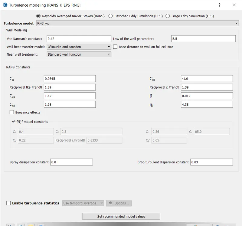
The RNG K-epsilon is selected for turbulence model and the values are kept default.
SOURCE/SINK MODELLING:
The two source is defined for spark plug.
SOURCE 1:
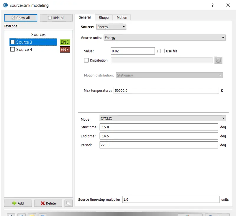
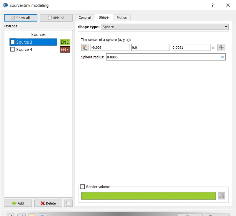
A source of 0.02 joule of energy and the sphere shape of 0.0005m radius is defined.
SOURCE 2:
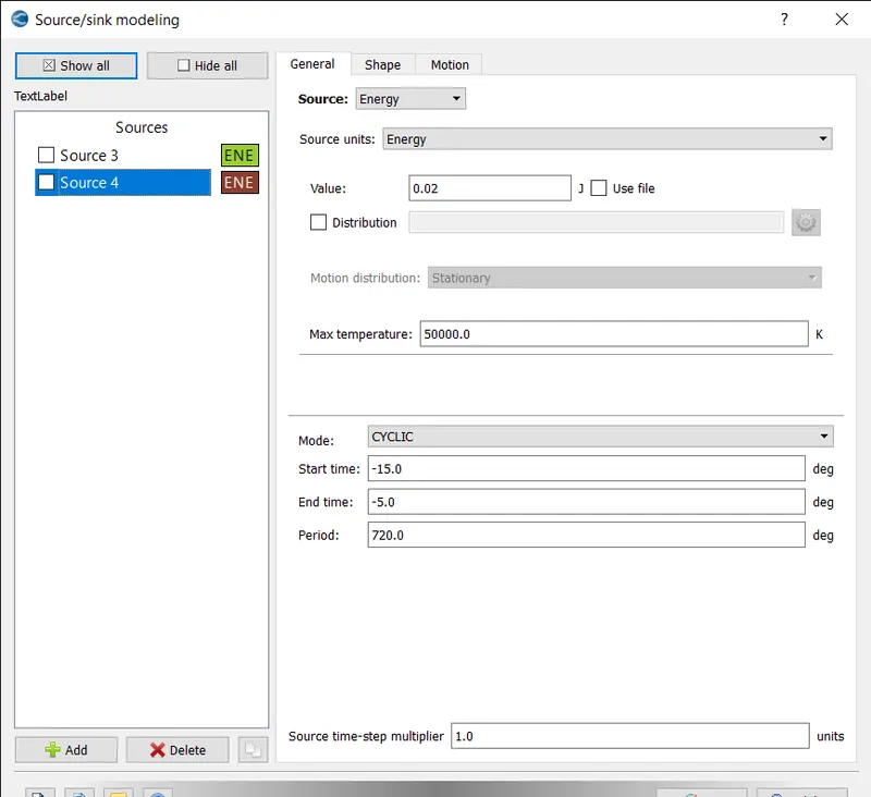
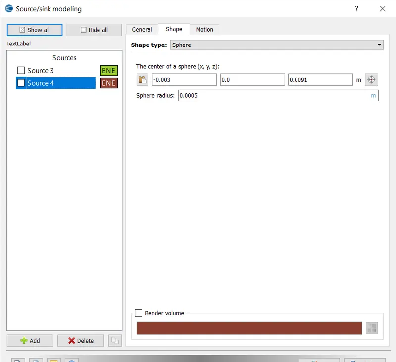
A source of 0.02 joule of energy and the sphere shape of 0.0005m radius is defined.
- GRID CONTROL:
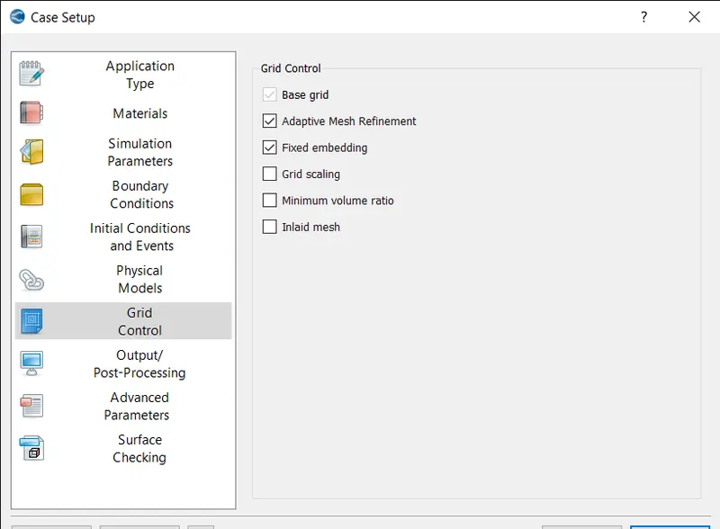
In grid control the fixed embedding and amr is selected.
- BASE GRID:
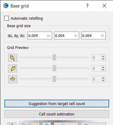
The base grids are defined as 0.004 m and press ok.
- ADAPTIVE MESH REFINEMENT:
VELOCITY AMR:
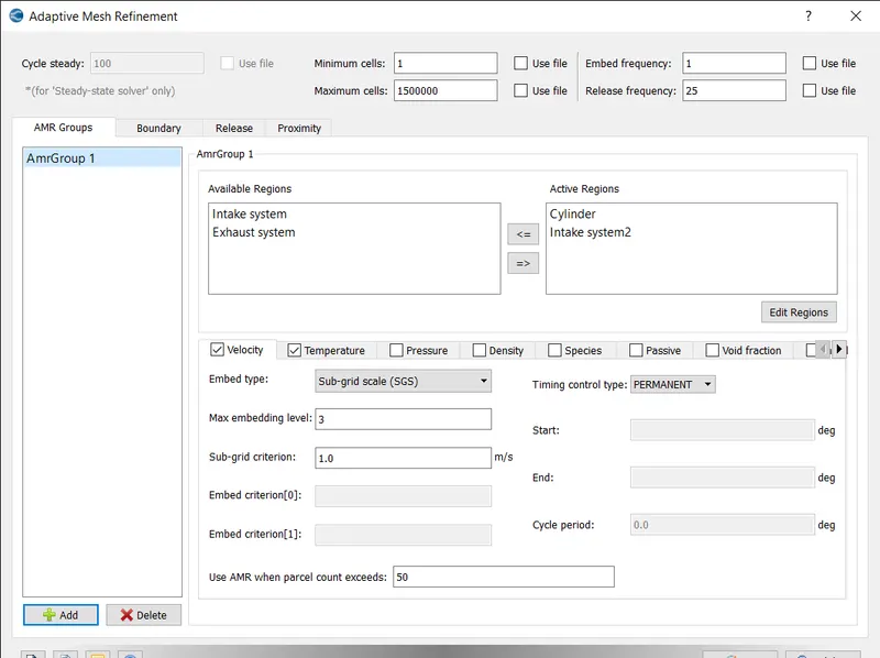
The velocity amr of permanent type SGS embed type of level 3 is specified.
TEMPERATURE AMR:
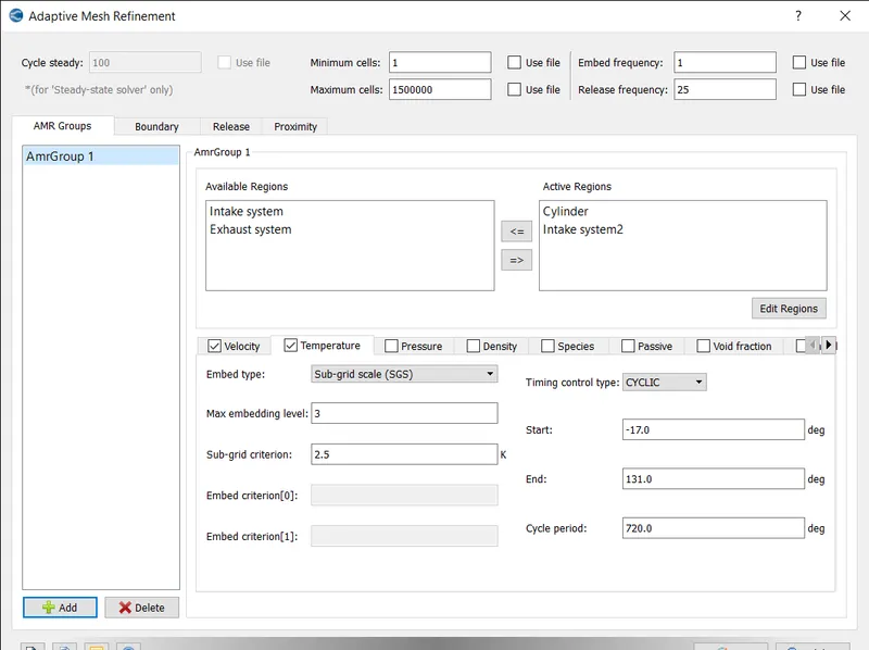
The temperature amr of cyclic type SGS embed type of scale 3 is defined.
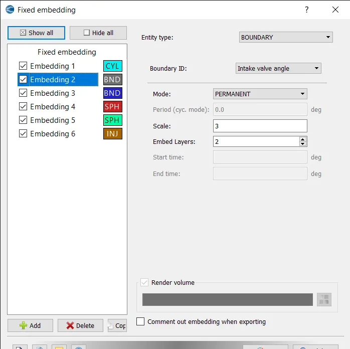
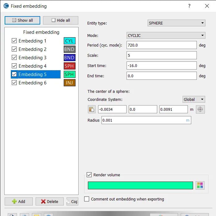
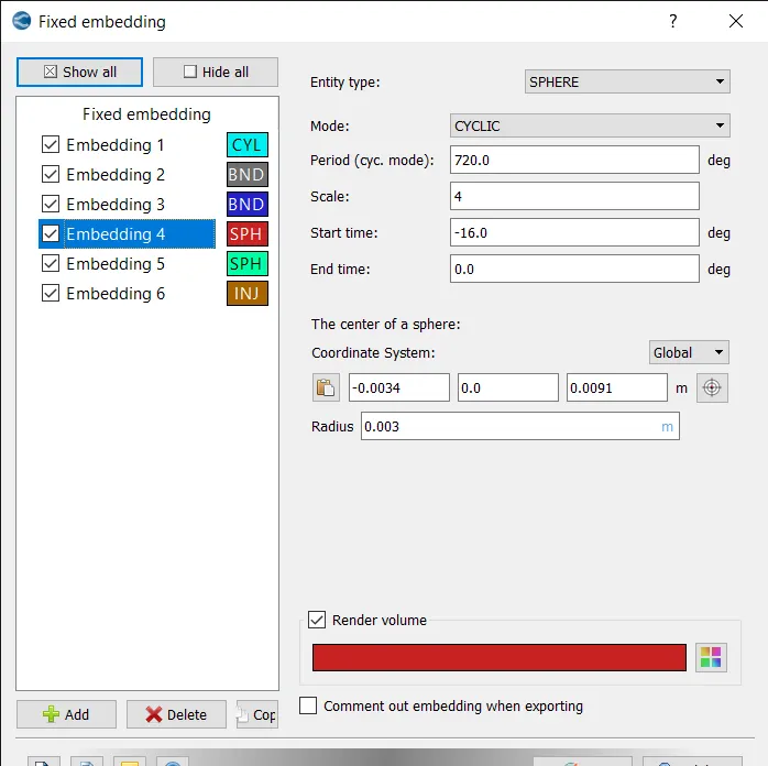
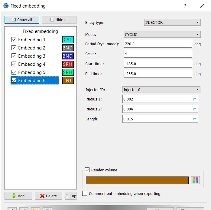
- FIXED EMBEDDING:
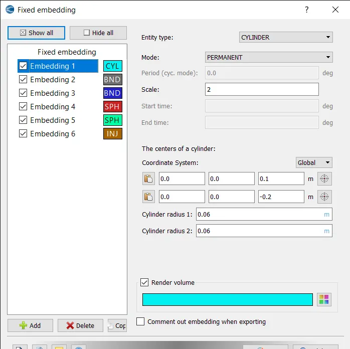
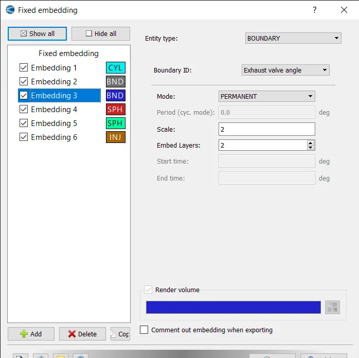
Fixed embedding is the feature which is used to add mesh to the required locations.
The fixed embedding is created for big cylinder, small cylinder, intake valve angles and exhaust valve angles.
CYLINDER EMBEDDING:
EXHAUST VALVE ANGLE EMBEDDING:
INTAKE VALVE ANGLE EMBEDDING:
SMALL SPHERE EMBEDDING:
BIG SPHERE EMBEDDING:
INJECTOR EMBEDDING:
- POST VARIABLE SELECTION:
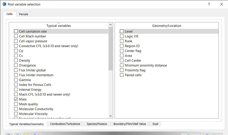
Keep the default values in typical variables tab.
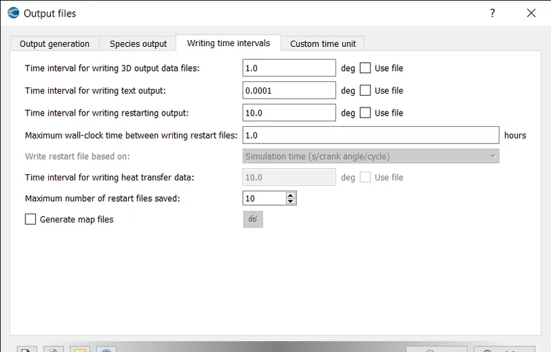
- OUTPUT FILES:
The interval for writing 3d output data files and restarting outputs are defined.
- Export the input files to a folder
- Then the executable is pasted inside the folder
- The simulation is run in Cygwin.
- The postconvert executable is pasted in the output folder.
- The post conversion is done on Cygwin and converted into the type that paraview reads.
- The results are then post processed using paraview and converge line plotting.
RESULTS:
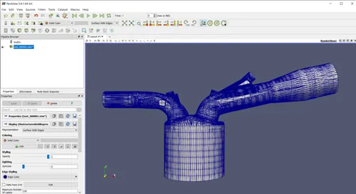
GEOMETRY:
PRESSURE PLOT:
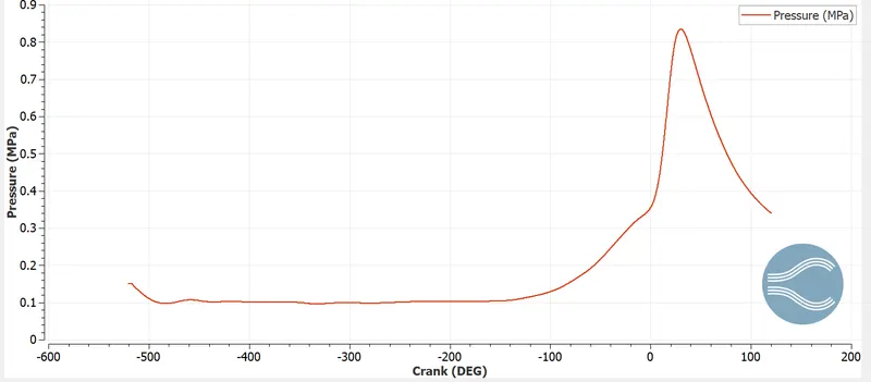
During compression stroke the pressure increases and then decreases rapidly due to expansion.
TEMPERATURE PLOT:
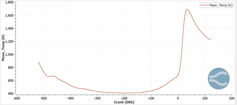
The temperature increases during compression stroke and reaches maximum once the spark gets ignitied and then decreases gradually.
VOLUME PLOT:
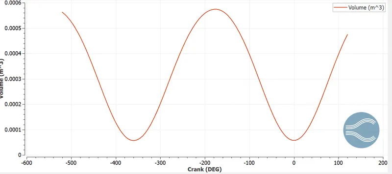
The ratio of maximum to minimum volume in the cylinder indicates the compression ratio.
The plot shows how the volume varies with respect to crank angle.
TOTAL CELLS:
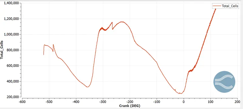
HR RATE:
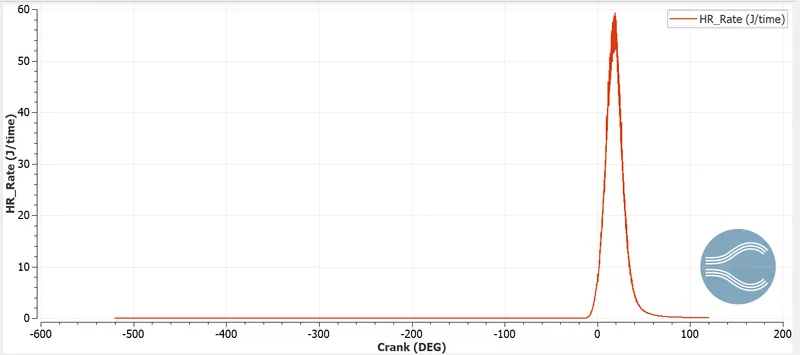
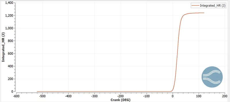
This plot indicates the amount of heat released during the period of cycles. The heat release rate is zero for maximum cycles and the maximum heat release is obtained where we provided the heat source for the model and then decreases at the end of the cycle.
INTEGRATED HR:
SOOT:
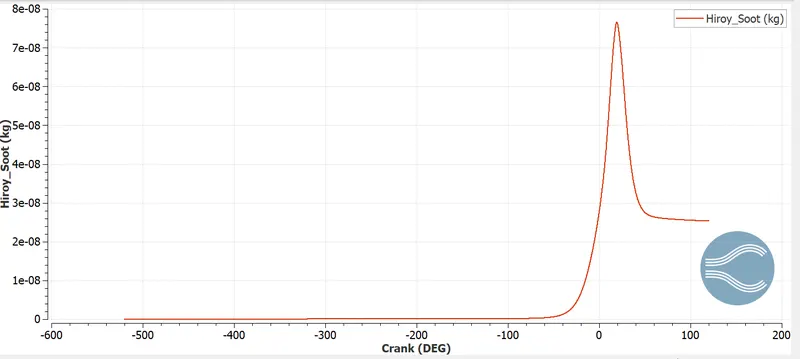
This plot shows the soot emission profile. Also the amount of soot emitted by the engine from the exhaust.
NOX:
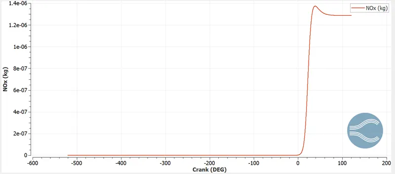
This plot shows the NOX emission profile. Also the amount of NOX emitted by the engine from the exhaust.
HC:
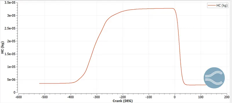
This plot shows the hydro carbon emission profile. Also the amount of HC emitted by the engine from the exhaust.
CO:
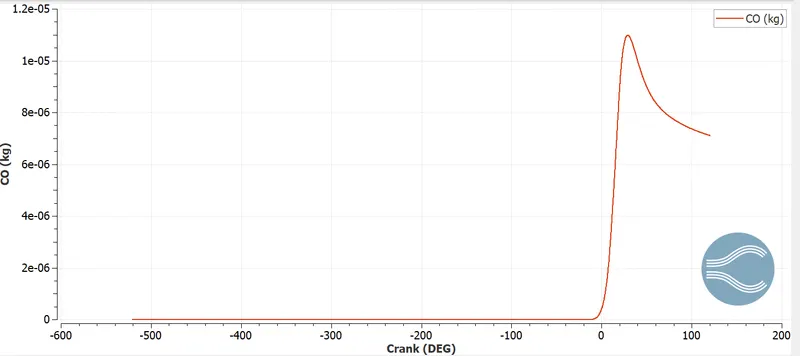
This plot shows the carbon monoxide emission profile. Also the amount of co emitted by the engine from the exhaust.
IC8H18 SPECIES:
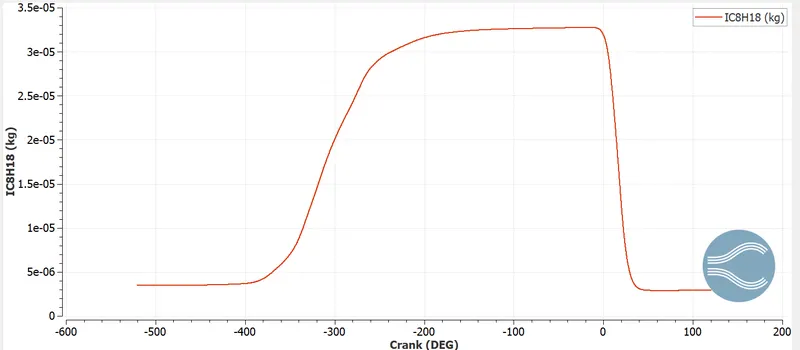
This plot shows how the IC8H18 species varies with crank angle.
ANIMATION:
https://drive.google.com/file/d/1zdgDMLrOGdOGdvzJU5adv_cGZ2vpJ1hs/view?usp=sharing
https://drive.google.com/file/d/1b9QaaIaf9gCTKLospsg5EX3qBeqj8pMx/view?usp=sharing
The above animation shows how the port fuel engine works.
1. COMPRESSION RATIO:
compression ratio is the ratio of maximum volume to minimum volume.
compression ratio = maximum volume /minimum volume
c.r = 0.00057/5.75*10-5 = 10:1
2. WALL HEAT TRANSFER MODEL:
For high accuracy of engine performance prediction modelling of wall heat transfer and wall temperature are necessary.
Better heat transfer model can produce better emission prediction, performance and combustion parameters.
In combustion chamber heat transfer takes place in all modes. When heat transfer takes place in multiple modes conjugate heat transfer is applied. Simulating IC engine flow along with CHT increases the computational time.
WHY CAN'T WE PREDICT THE WALL TEMPERATURE FROM CFD SIMULATION:
In the IC engine combustion is based on chemical reaction. During the combustion phase the air-fuel gets mixes up and gets ignited by the spark plug. These chemical reaction raises the temperature inside the chamber.
In our simulation the computation takes lot of time to solve the geometry to complex shape. The n-s equation is solved in each cell volume it would take lot of time to solve. So certain physical models are used to approximate the computational time. Wall heat transfer model are focused on heat transfer rather than fluid simulation.
3. COMBUSTION EFFICIENCY:
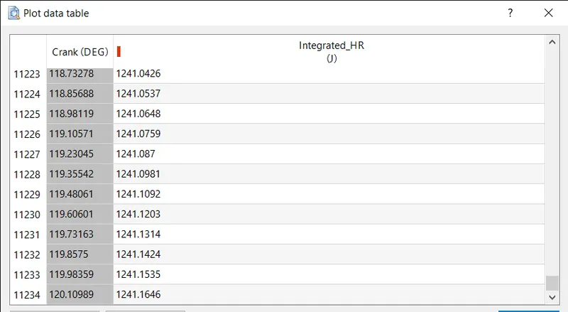
Total heat release = 1241.1646J
Calorific value of gasoline = 44MJ/KG
Fuel mass per cycle = total flow rate *time per 720 degree = (7.5 e-4) * 0.04 = 3e-5kg
Total energy content = cv * fuel mass per cycle = 1320J
Efficiency = 1241.1646/1320 = 94.02%
4. CALCULATION OF POWER AND TORQUE:
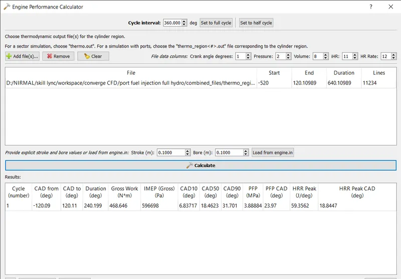
Power = 2*pi*N*T/60
Power = work/time
Work = 468.646 N-M
Time = duration / degrees per second = 240.199/18000 = 0.0133 sec
POWER (P) = 468.646/0.0133 = 34.189 KW
N = 3000 rpm
P = 2*phi*N*T/60
34.819*60/(2*pi*3000)
TORQUE (T) = 11083 N-m
5. What is the significance of ca10, ca50 and ca90?
The crank angles values are derived from engine performance tool from the converge software.
The ca refers to crank angle followed by its position in degree at 10, 50 and 90% of combustion. The significance of ca 10 determines the start of ignition, ca 50 determines the end of premixed combustion and ca90 determines the burning of unburnt fuel inside the combustion.
CONCLUSION:
- The hydro simulation has run successfully to operate the combustion process and measure performance parameters.
- Refinement of mesh using fixed embedding and adaptive mesh refinement technique has been applied at different zone of interest.
- Performance calculator has been used to capture the work done during one cycle of simulation.
- Combustion, compression ratio, torque and power calculation are performed to measure the performance of PFI engine.