Week 10: Project 1 - FULL HYDRO case set up (PFI)
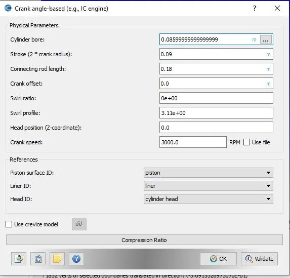
Problem:- Aim of Problem is to study Port fuel injection SI Engine with Bore 86mm,Stroke 90mm and Connection Rod length 180mm Running at 3000RPM.Calculate Parameters given Below:-
1. What is the compression ratio of this engine?
2. Why do we need a wall heat transfer model? Why can't we predict the wall temperature from the CFD simulation?
3. Calculate the combustion efficiency of this engine
4. use the engine performance calculator, to determine the power and torque for this engine.
Solution:- A geometry with Required size is setup in converge studio as shown Below.As Successfully done Surface Prepration and boundary Flagging and run No Hydrodynamics Case.Now to get Results same case will be run with full Hydrodynamics.
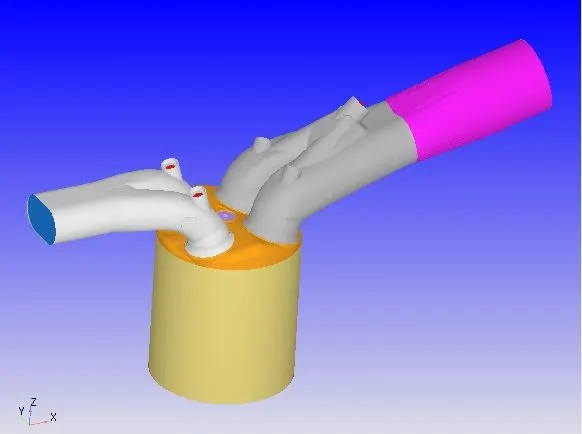
Boundary Flagging
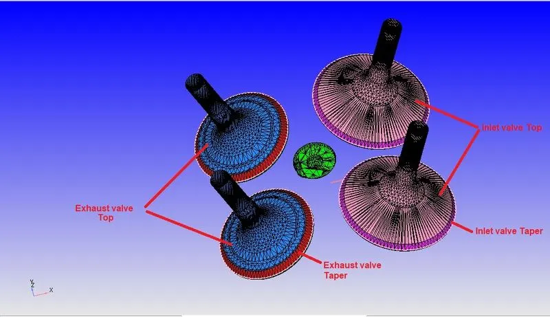
Keep Boundary flagging of Geometry and define liner,Piston,Cylinder Head,valves,Intake Port and Exhaust Port as shown below.
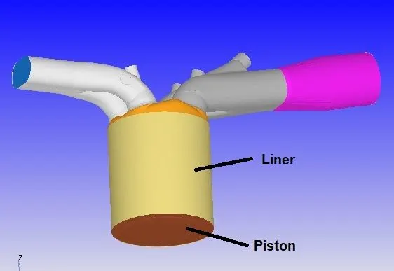
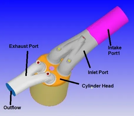
Engine Parametes
Engine Parameters are given Below
Parcel
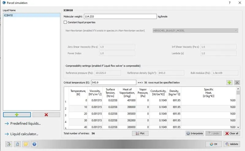
Choose Predefined Fuel of IC8H18 Mix with air to inject into cylinder as shown below.upload Mech.dat and Thermo.dat file to Upload Thermodynamics and Physical Propeties.It has Physical properties closer to Gasoline Fuel.
Simulation Parametes
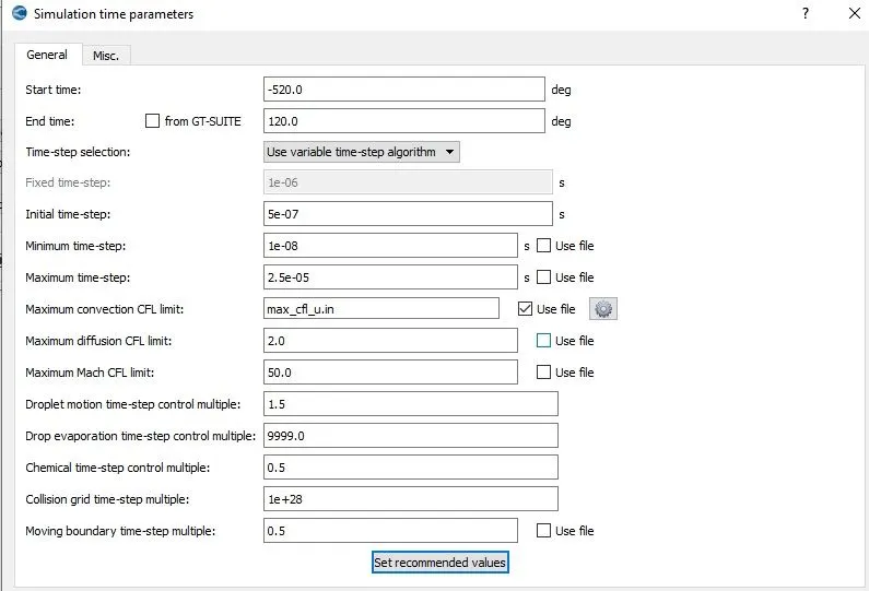
Run full Hydrodynamics Case with simulation Parametes given below
Boundry condition
Boundary conditons and Region Condition are given in Below tabulated form
| Boundary Flagging | Boundary Type | Temperature | Velocity | Pressure | Species |
| Piston | Wall | Law of Wall 450K | Wall Motion Type,Translating Moving Surface,Piston Motion | ||
| Liner and Head | Wall | Law of Wall 450K | Stationary, Law of wall | ||
| Spark Plug | Wall | Law of Wall 550K | Stationary, Law of wall | ||
| Spark Plug | Wall | Law of Wall 600K | Stationary, Law of wall | ||
| Exhaust Port | Wall | Law of Wall 500K | Stationary, Law of wall | ||
| Exhaust Outflow | Outflow | 800K | zero Normal Gradient | 103737Pa |
N2-0.71913 Co2-0.19235 H2O-0.088525 |
|
Exhaust valve Top Bottom, and Angle |
Wall | Law of Wall 525K | Wall Motion Type Traslating, Surface Movement-Moving, Law of Wall, User Specifies:-Exaust_Lift Profile | ||
| Intake Port | Wall | Law of Wall 425K | Wall of motion,Stationary | ||
| Intake Flow | Inflow | 363K | zero Normal Gradient | 101325Pa | N2- 0.77,O2-0.23 |
| Intake Valve Top,Bottom,Angle | Law of Wall 480K | Wall Motion Type Traslating, Surface Movement-Moving, Law of Wall, User Specifies:-Inlet_Lift Profile |
Region Initial condition and Events
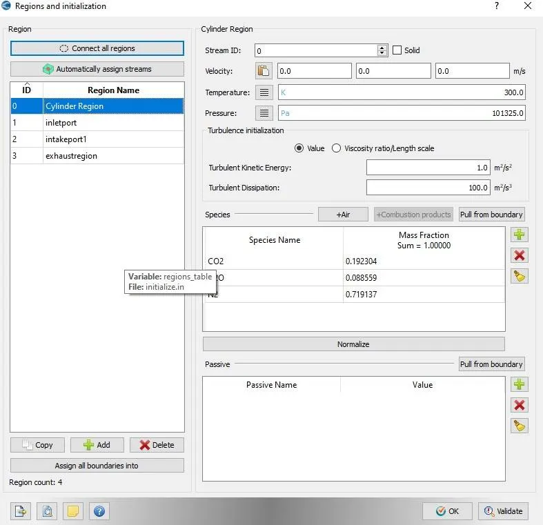
click on Region Option and Define four region as shown below
(1) Cylinder Region
T= 300K
P= 101325 Pa
Species:-
Co2 = 0.192304
H2o = 0.088559
N2 = 0.719137
Species Fraction is calculated from Mole Fraction by balancing Reaction Equation.
(2) InletPort
T= 390K
P= 101325Pa
Species:-
IC8H18(Fuel) = 0.025508
O2 = 0.20157
N2 = 0.77292
Species Fraction is calculated from Mole Fraction by balancing Reaction Equation.

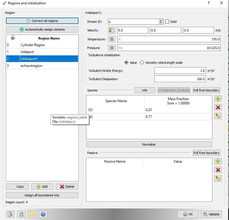
(3) Intake Port-1
T= 370K
P = 101325pa
Species:-
O2 = 0.23
N2 = 0.77
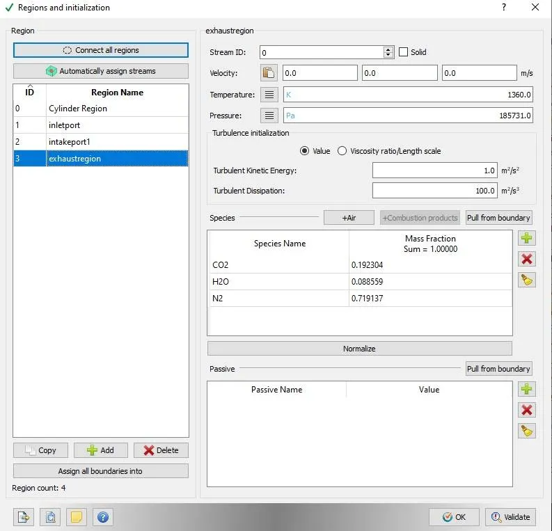
(4) Exhaust Region
T= 1360K
P= 185731 pa
Species:-
Co2 = 0.192304
H2O = 0.088559
N2 = 0.719137
Species Fraction is calculated from Mole Fraction by balancing Reaction Equation.
Region
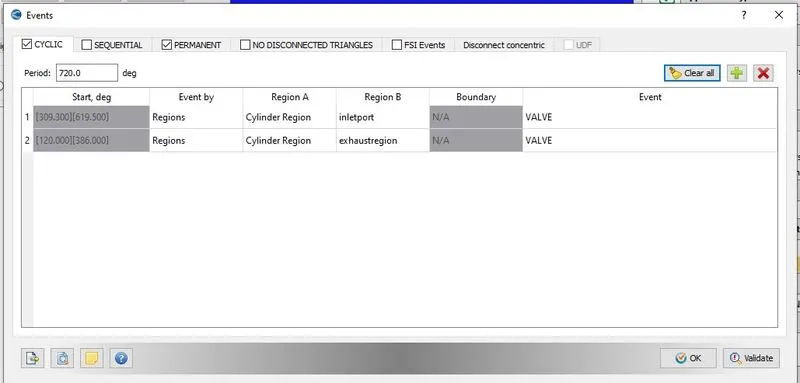
Join Cylinder region and inletport region with valve event in Cylic option. so contact into these region will maintain by opening and closing of valve. Simillarly cylinder region and Exhaust Region will be contact by valve Event.
Embedding
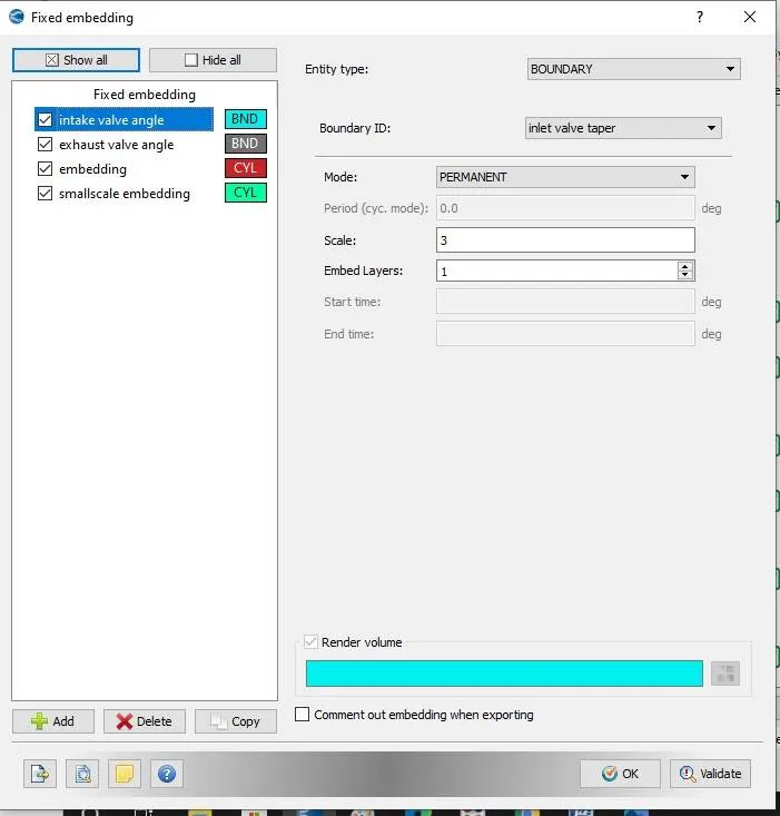
Set Intial base grid size to dx=0.04, dy= 0.04 and dz =0.04 and then apply fixed embedding on different region for mesh refinement to get accurate result. The boundary embedding region are inlet valve Taper Region so when valve will open or close the mesh size will refined to get accurate resutls. Mesh embedding for Inlet valve region is shown below.
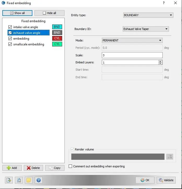
Mesh embedding for Exhaust valve region is shown below. there is scale factor of 3 so first mesh will refined to 0.02, then 0.01 and then 0.005.
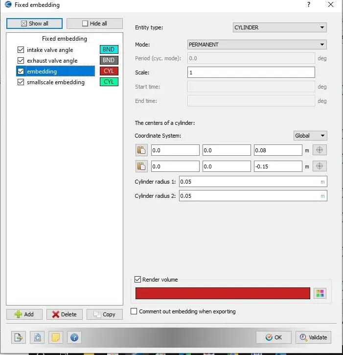
AS Piston will move upward and downward so fixed embedding is also apply on cylinder region with scale of 1.
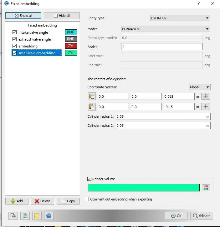
AS Piston will move upward and downward so fixed embedding is also apply on cylinder region with scale of 2.
Run Simulation in Full Hydrodynamic Mode with simulation Parameters given below
Export file in IC engine folder and Open cygwin and run simulation. it will generate output files. Then through converge 3d Post out file, convert output file to binary vtk inline binary format. Paraview will Open this format and we can animate IC Engine in Paraview software.
Results
(1)Compression Ratio
Compression Ratio is the ratio of total volume of Engine divided by clearance volume of Engine.
CR= Total Volume/ Clearance Volume
= Stroke volume+ Clearance Volume/Clearance volume
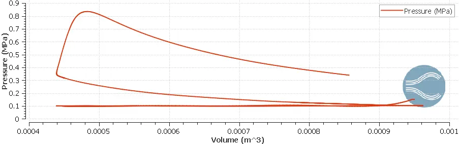
From Graph
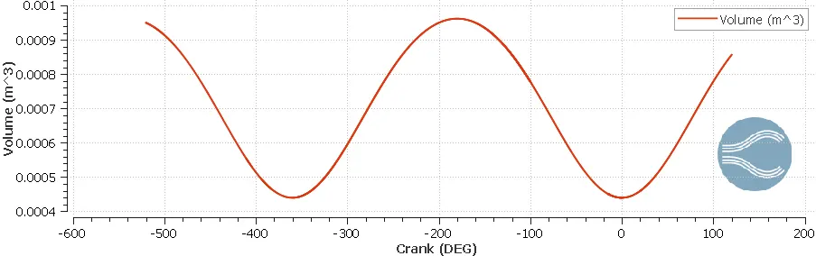
Vt=.000961775 m3
VC= .000439574 m3
CR= .0000961775/.000439574= 2.18
(2)Wall Heat Transfer Model
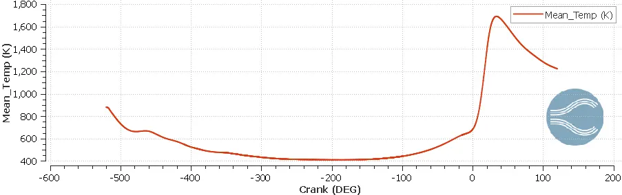
The Heat Loss through wall is an impotant parameter as it influence powr,emmision and engine efficiency. As during combustion wall temperature is less than combustion temperature.So when combustible product comes in contact with wall, it is main reason of generation of HC gas. The combustion Temperature Generated in Combustion chamfer are taken as boundary condition. In this case mean temperature is around 1700k. with boundary condition of this temperature thermal analysis of cylinder wall is done
For the PFI Engine simulation it takes lot of time to compute the case as it contin complex geometry. for this if we want to compute the heat transfer we need to solve energy equations to get convection of heat from liquid solid surface. Hence increase computational time. thus it difficult to take wall temperature for cfd simulation.
(3)Combustion Efficiency
Combustion Efficiency is amount of heat realesed During combustion inside engine over theoratical Energy realeased by Fuel during engine one complete cycle
From graph of integrated heat Release,it represent heat released during Combustion Process.
Integrated Heat Release=1241 J
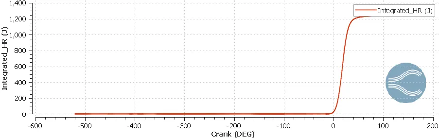
Theoratical heat released by fuel Isooctane = Lower heating value x fuel injected
=44400 KJ/Kg x 3e-5 kg
Combustion efficiency = 1241/44400x3e-5
Combustion efficiency = 0.9315= 93%
Engine calculator
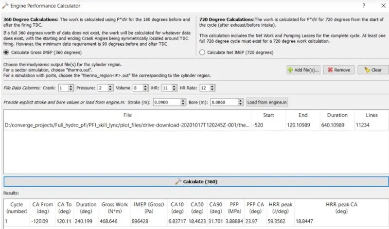
Work done= 468.646
Combustion Duration = 240.19 deg
Crank Speed = 3000RPM= 50RPS
Number of Degree Per Second= 18000DPS
Time for one Degree= 5.555E-05 second
Time Duration for Combustion= 5.555e-05x 240.19
= .01334 second
Power = work Done/time taken for combustion
= 468.646/.01334 = 35.13kw
Torque = Px60/ 2xPixN
35.13x1000x60 / 2x3.1417x3000= 111.8Nm

Plots
P vs crank angle graph show pressure rise in combustion chamber during combustion
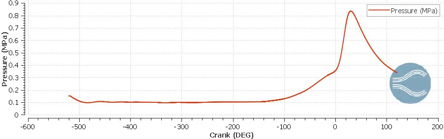
Meam temperature
P-V Diagram
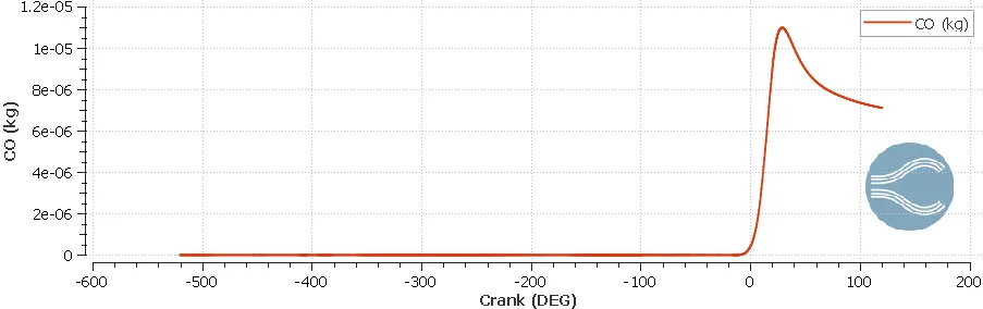
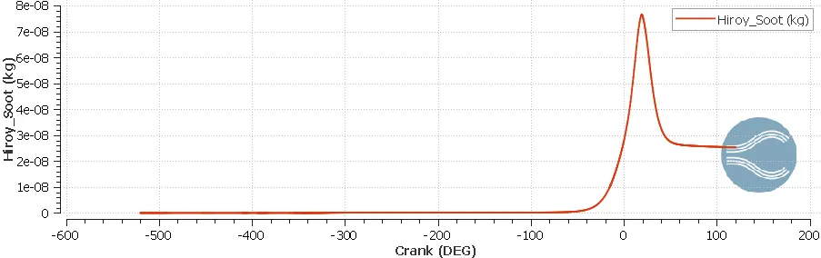
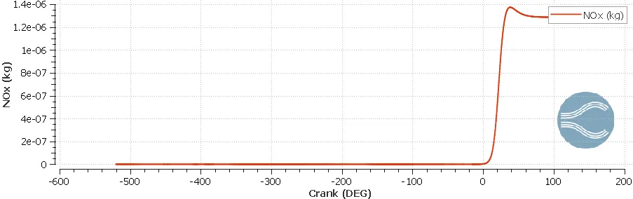
Emmision Graphs
Soots Graph
Nox Graph
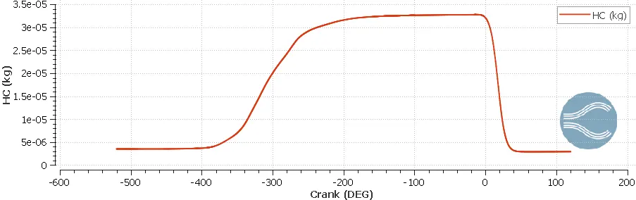
HC Graph
CO Graph