Week 10: Project 1 - FULL HYDRO case set up (PFI)
PFI ENGINE (FULL HYDRO SETUP)
AIM: Setup the case for a port fuel injection engine(PFI), simulate the PFI engine in paraview and study the engine performance characteristics.
THEORY: In this case the entire case setup depends mainly on the combustion and the spray modelling modules on the case setup tree. In the spray modelling particles are spread from the injector nozzle and the combustion takes place in the combustion chamber. The fuel is ignited at the spark plug terminal with a sufficient amount of energy by source/sink modelling which generates the energy source to the entire spark plug assembly.
SPRAY MODELLING: Converge can use a gaseous or a liquid sprays. For gaseous sprays converge can use eulerian solver which set the species mass fraction and mass flow rate at the inflow boundary. For liquid sprays converge uses langragian solver to solve the heat, momentum and the mass transfer equations.
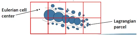
Parcels refer to the group of identical particles with the same velocity, temperature and the radius. Parcels undergo several processes namely
- Primary breakup: When fuel injection takes place the liquid spray breaks up into tiny particles, this is known as the primary breakup
- Secondary breakup: These tiny particles undergo further breakup and is called the secondary breakup
- Drop drag: When the spherical interact with the ambient air then their shapes may get affected which causes drop drag
- Evaporation: The rate at which the radius of the drop decreases due to evaporation
- Collision and coalescence: The drop collides to form smaller drops or coalesce to form larger drops
- Turbulence dispersion: It explains about how the fluctuating velocity affects the drop.
SPRAY MODELLING SETUP:
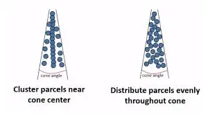
Parcel distribution: For solid cone sprays converge assumes the injection is conical. For gasoline engine the parcels that occur in the form of cone is better than the cluster based parcels particles.
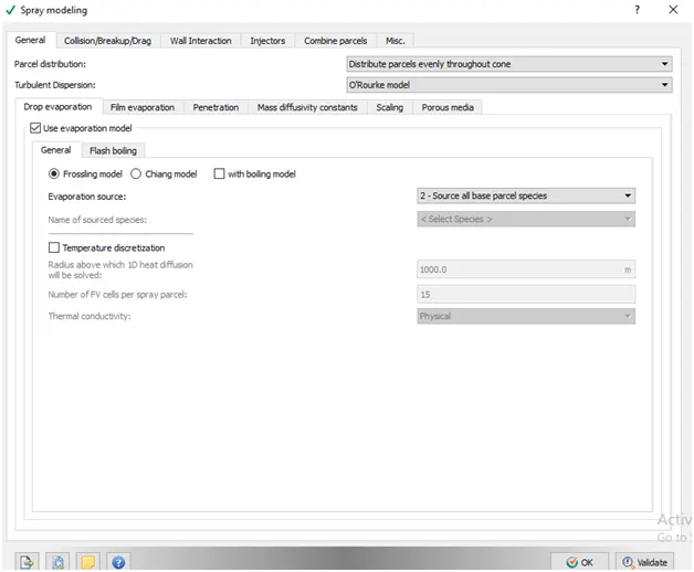
EVAPORATION MODEL: It describes the rate at which the radius of the drop shrinks and the rate at which the mass is being transferred. Frossling model is being used here.
EVAPORATION SOURCE: source of all base parcel species means that the fuel we use IC8H18 is being converted from its liquid state to the gaseous state because the gas phase chemistry can be easily captured in that state. ‘Source all composite parcel species is used when there are two or more species being used.
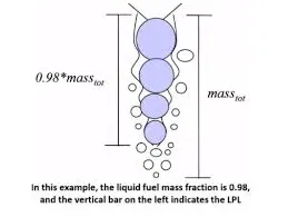
LIQUID MASS FRACTION FOR CALCULATING SPRAY PENETRATION:
When fuel injection takes place the some of the fuel my evaporate due to high ambient temperatures whereas some of the fuel might expand a bit and penetrate/travel to some length which may include the total length of the combustion chamber. This length is called the Liquid penetration length and is calculated based on the injector axis.
Bin size for calculating the vapour penetration and fuel vapour mass fraction for calculating vapour penetration: The recommended bin size is said to be twice the length of cells in the spray cone.
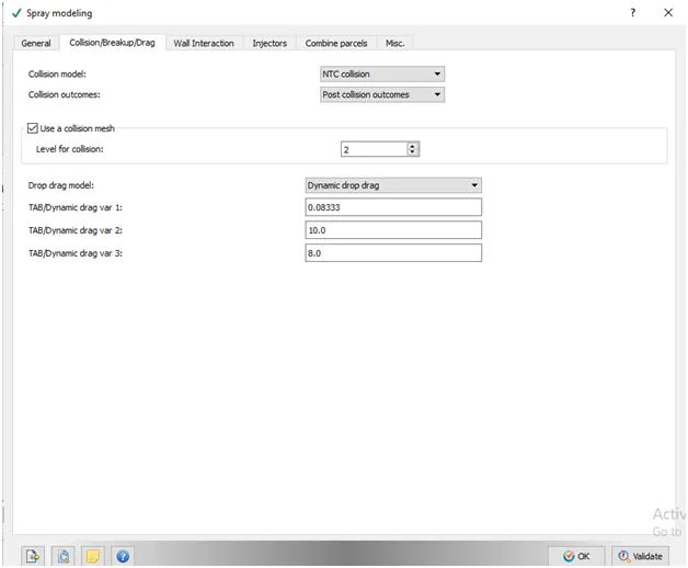
USE COLLISION MESH: In a typical spray simulation we always assume that the particles collide in real time applications so it affects the grid sensitivity. So we always use a collision mesh for better accuracy of the grid cells.
DROP DRAG MODEL: Calculates the drag coefficient of the drop shape. This model is mostly preferred
SPRAY WALL INTERACTION MODEL: Wall film is selected because the drop motions are captivated because of the film formation of the particles.
INJECTOR: IC8H18 is the parcel species with a mass fraction of one. Rate shape tells how the injector is going to spray the fuel.
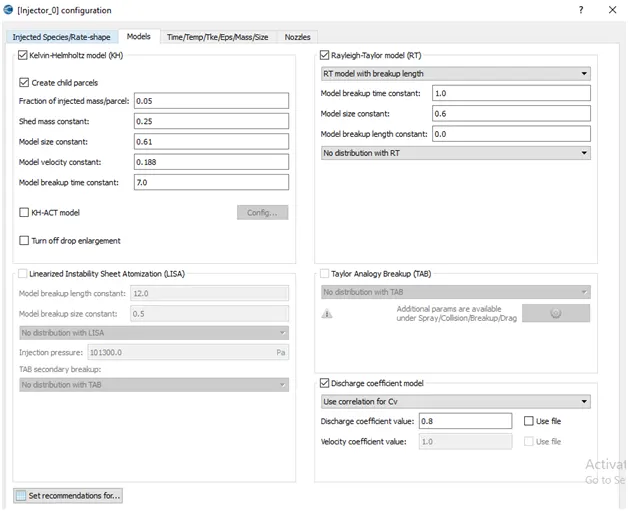
KH-RT Model is used because they are preferable for solid cones and LISA for hollow cones. The values of the KH model will tell us how the parcel disturbances will take time to be stable.
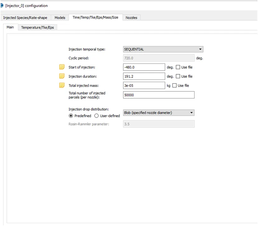
NOTE: The RPM of the engine is 3000 by converting it into RPS we get it as 50. Further converting it into revolutions per degree is 1800.Hence te time per degree is 5.55E-05. Time for 720 degrees is 0.04. Now the fuel mass per cycle is calculated by the product of fuel flow rate (7.5E-04) and Time per degree (0.04). The obtained fuel mass per cycle is 3.0E-5.
NOZZLE: 4 nozzles were created in the injector with these parameters
NOZZLE DIAMETER: 250 micro meters
Circular injection radius: Nozzle radius
Spray cone angle=10
Nozzle 0
Centre= 0.0823357 0.00100001 0.07019
Align vector -0.732501 0.210489 -0.647408
Nozzle 1
Centre 0.0823357 -.0009999 0.07019
Align vector -0.732501 -0.210489 -0.647408
Nozzle 2
Centre 0.00823357 -.0009999 0.07019
Align vector: -0.5 -0.2 -0.647408
Nozzle 3
Centre 0.0823357 0.0003 0.07019
Align vector -0.5 0.2 -0.647408
Combustion modelling: It uses a SAGE based solver which is the most predictive and accurate way to model combustion. Simplified combustion models are generally less expensive and can provide less accurate results for IC engine applications.
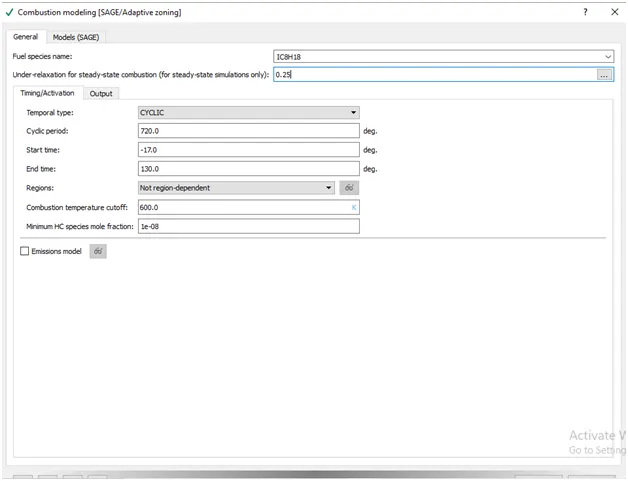
COMBUSTION TEMPERATURE CUTOFF AND MINIMUM HC SPECIES MOLE FRACTION: Increases the cell temperature to make sure the temperature is adequate and there are enough number of cells to perform combustion.
START TIME AND END TIME: The combustion starts certain angle before the spark begins and the end time is when the exhaust valve opens right after the combustion process is over.
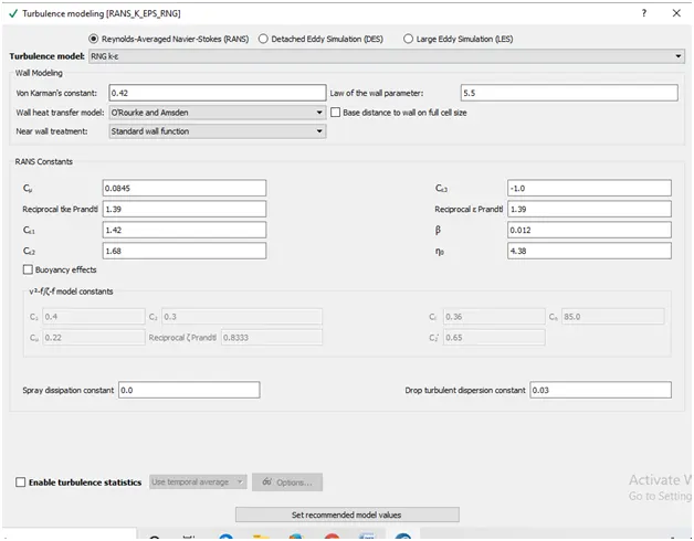
TURBULANCE MODELLING: Turbulence is the state of chaotic and unstable fluid flow. In turbulence modelling increases the rate of mixing although mixing would require cells in the order of 1e-6.
RANS SOLVER: solves equations for a time averaged velocity field and magnitude of turbulent fluctuations.
SOURCE/SINK MODELLING: In source/sink modelling we give energy as an input to the spark plug and as a result the source i.e. the spark plugs temperature will increase and will cause combustion of the fuel and will result in the bi products.
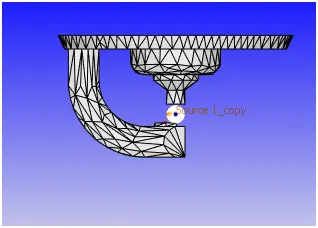
Start of spark =15deg
Spark duration= 10deg
Spark location= -0.003 0 0.0091
Spark radius= 0.0005m
Reason behind two spark source:
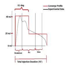
One energy source will provide 20mj for 0.5 degree and for 10degree 20mj is provided by another source. Hence we use 2 spark sources and provide fixed embedding to capture the equations.
FIXED EMBEDDING:
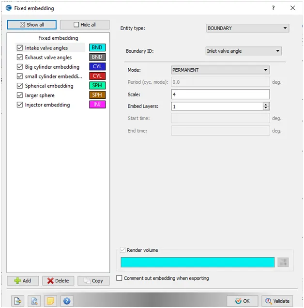
Fixed embedding mesh size= base grid size/2^n
Base grid size=0.004m
N=4
Fixed embedding=0.004/2^4= 0.00025m
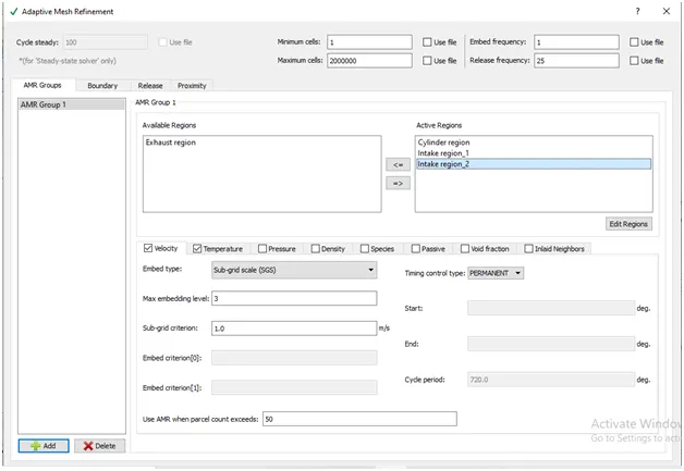
ADAPTIVE MESH REFINEMENT: A temperature and a velocity based adaptive mesh refinement is given. A temperature criterion of 2.5k is given and a velocity sub grid criteria of 1m/s is given.
RESULT:
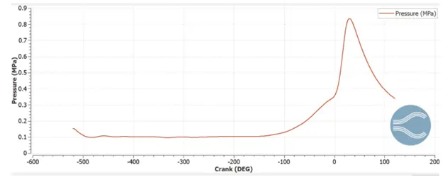
PRESSURE PLOT:
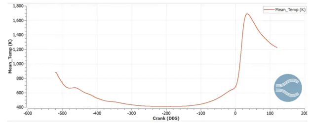
TEMP PLOT:
Compression Ratio of engine(CR): It is the ratio of volume of the cylinder and the combustion chamber when the piston is at bottom of its stroke and the volume of combustion chamber when the piston is at the top of its stroke.
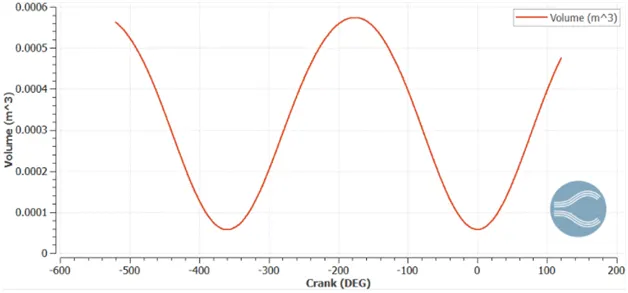
CR= VT/VC
From the graph VT= 0.00572m3 and VC= 5.70289e-3
CR= 10.06:1
Why do we need a wall heat transfer model? Why can’t we predict the wall temperature from the CFD simulations?
CFD solver only the navier stokes equation which comprises of the momentum, energy and the continuity equations. Wall heat transfer model is used to find the temperature at the wall using conduction, convection and radiation.
COMBUSTION EFFICIENCY:
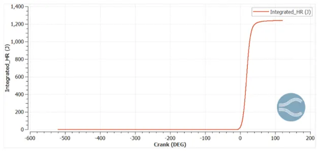
Integrated_HR= Total heat released=1241J
Total amount content of fuel= amount of fuel* calorific value of fuel
Amount of fuel= 3*10^-5
Calorific value= 44MJ/K
Total energy content =1320J
Combustion efficiency= (1241.1/1320)*100
Combustion efficiency= 94.02%
POWER AND TORQUE OF ENGINE: Calculated using engine performance calculator by adding thermo.out file from the cylinder region
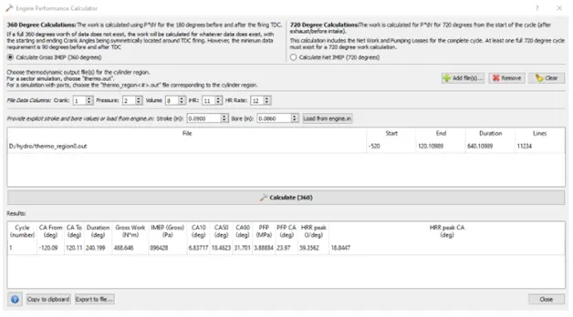
From the image above
Work done= 468.646J
Duration= 240.99 degrees
Power output= work done/time
Convert degrees to seconds
Time per degree- 60/(360*3000)= 5.55*10^-5 sec/deg
For 240 degree= 0.0133sec
Power= 35.16KW
TORQUE:
T= P*60/(2*PI*N)
T= 111.97Nm
Volumetric efficiency: is the ratio between the actual measured volume of the intake and the theoretical volume of the air taken into the engine during the intake.
Nv=va/vd
P*va=mRt
P=pressure at the inlet
R= gas constant=287
T= temperature at the inlet
Va= 0.0004537m^3
Therefore volumetric efficiency- 87.63%
Significance of ca10,ca50 and ca90
Ca10 (onset of combustion) = Crank angle is 10% of the mass burnt. Its value is 6.83717 degrees
Ca50( combustion phase) = Crank angle is 50% of the mass burnt or the heat rate is 50% of cumulative heat released It’s value is 18.4623 degree
Ca90( Burn phase) = Crank angle of 90% of mass is burnt or the heat rate is 90% of cumulative heat released. It’s value is 31.701 degrees.
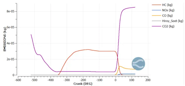
EMISSION PLOT: