Week 10: Project 1 - FULL HYDRO case set up (PFI)
Aim: To set up combustion simulation in an IC Engine in Full hydro using Converge.
Objective:
1. What is the compression ratio of this engine?
2. Why do we need a wall heat transfer model? Why can't we predict the wall temperature from the CFD simulation?
3. Calculate the combustion efficiency of this engine
4. use the engine performance calculator, to determine the power and torque for this engine.
5. What is the significance of ca10, ca50 and ca90?
Methodology:
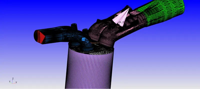
The full model is imported in the converge interface. This process is carried forward from the case setup of NO-Hydro simulation.
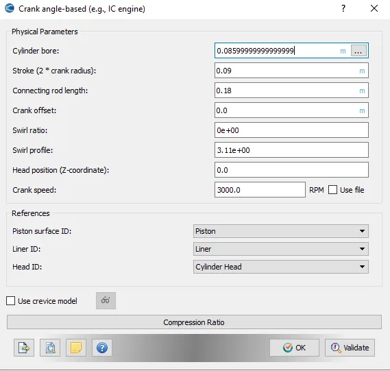
Case Setup: Crank based IC engine is selected. The parmeters inserted are shown below
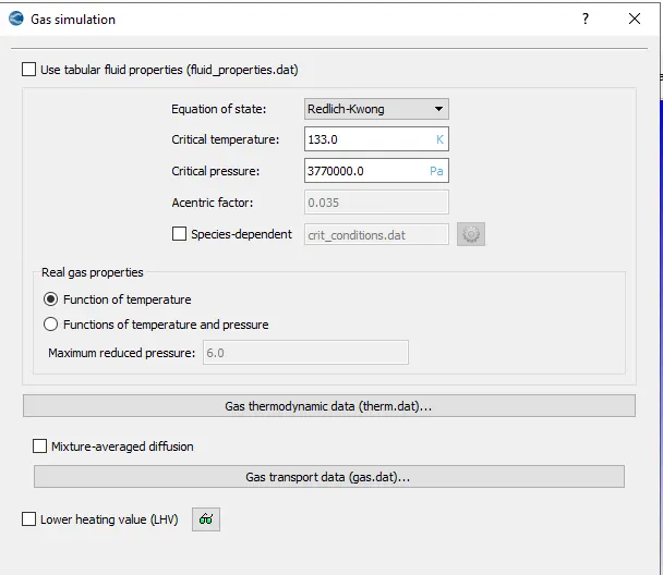
Gas simulation parameters are kept to be default.
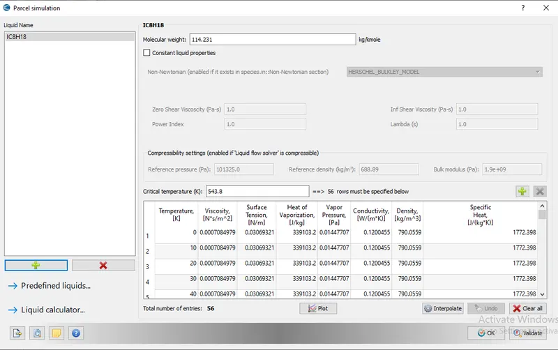
In the parcel simulation, IC8H18 is selected
For reaction mechanism Therm.dat and Mech.dat are selected.
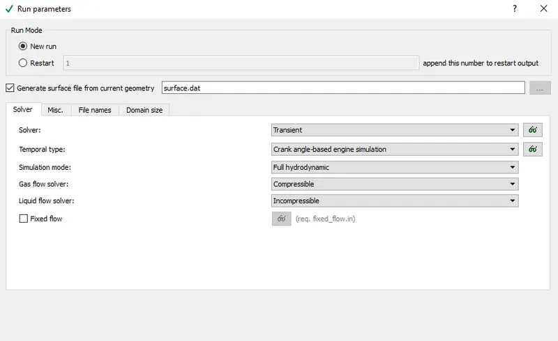
Run Parameters:
Since it is a time based calculation. So trasnient mode is selected here along with full hydrodynamic.
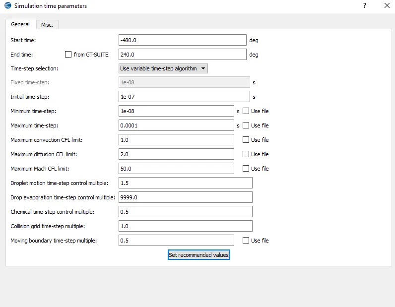
Simulation time paramters are selected as below-
For solver parameters, PISO scheme is selected.
Regions and Initialization:
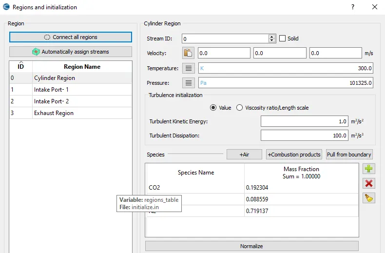
Cylinder Region:
A stoichiometric combustion is assumed so it gives us the equation to be,
`C_8H_(18)+12.5{O_2+3.76N_2}rightarrow8CO_2+9H_2O+47N_2`
From the above stoichiometric equation, mass and then mass fraction are calculated which are thus inserted in the Regions tab.
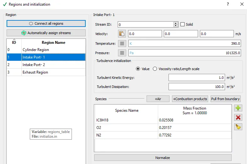
Intake Port-1:
Defined the amount of air fuel fuel mixture which will be introduced in the engine.
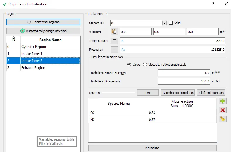
Intake Port-2:
Only air is introduced through this port.
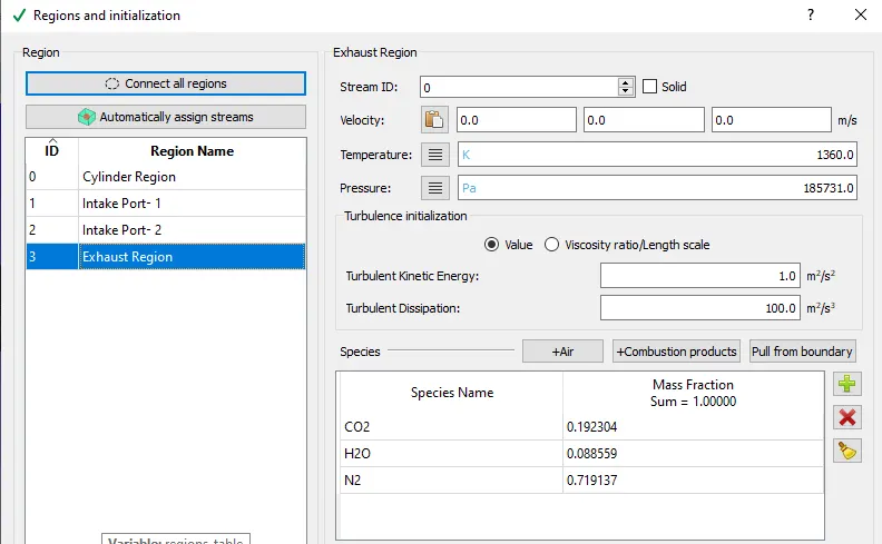
Exhaust Port:
Composition is similar here as in the combustion chamber.
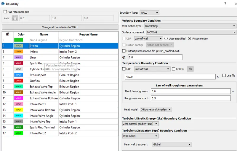
Boundary Conditions:
Piston:
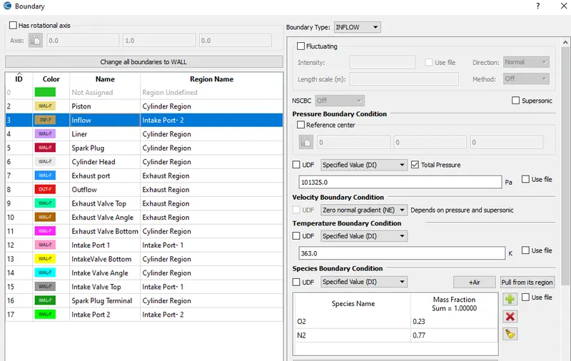
Inflow:
Liner:
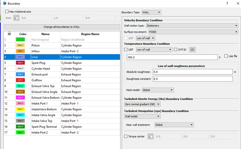
Spark Plug:
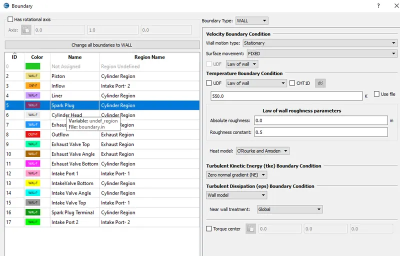
Cylinder head:
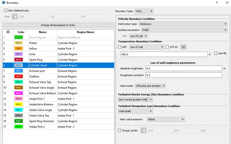
Exhaust Port:
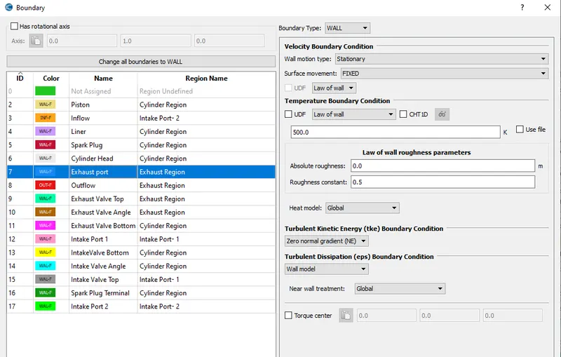
Outflow:
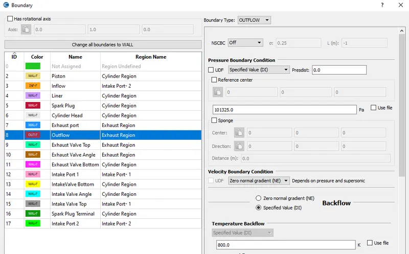
Exhaust valve top:
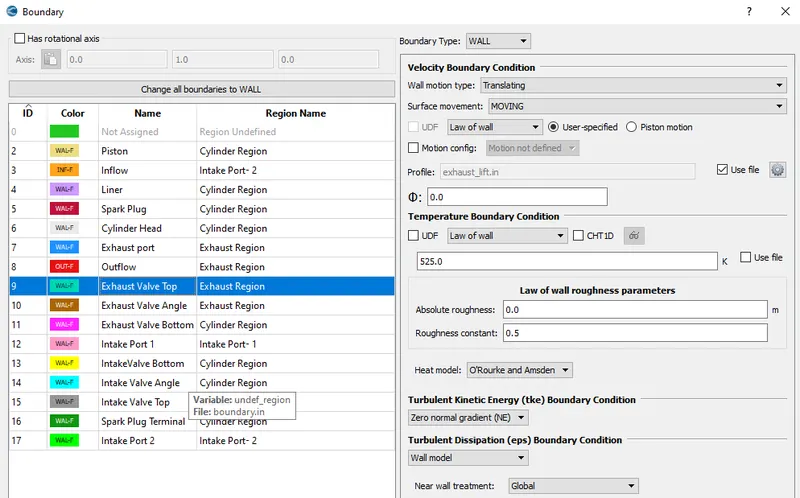
Exhaust Valve angle:
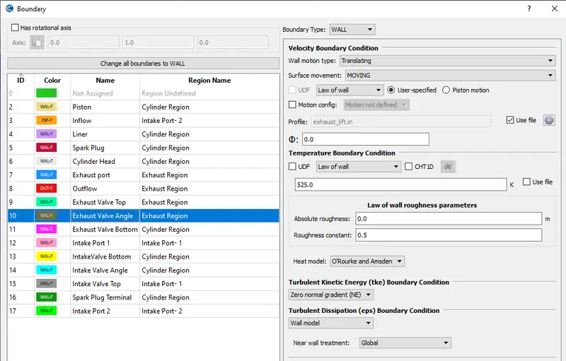
Exhaust valve bottom:
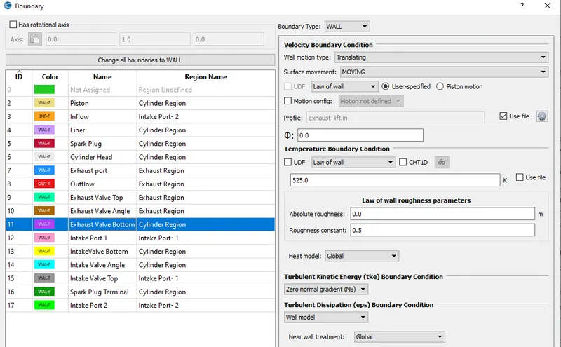
Intake port 1:
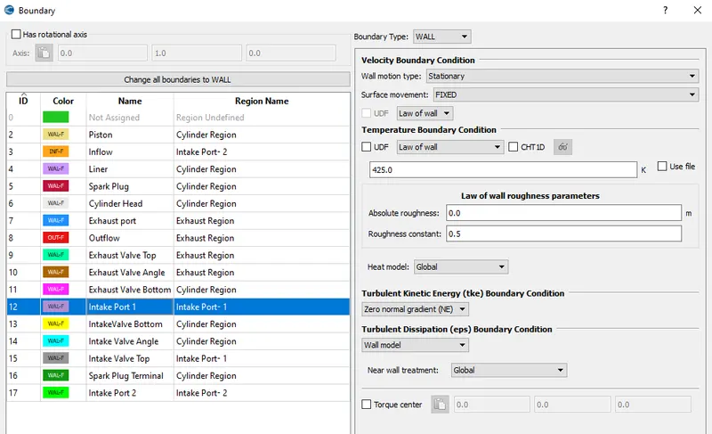
Intake valve Bottom:
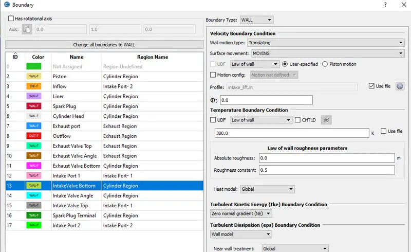
Intake Valve Angle:
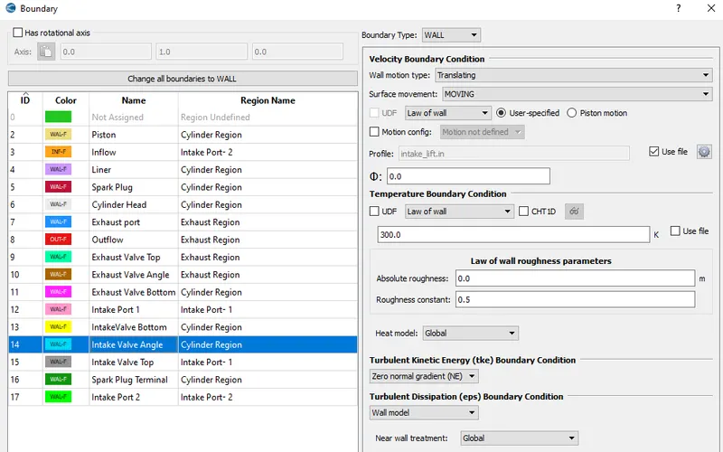
Intake Valve top:
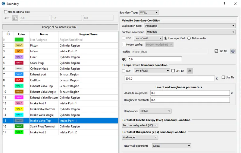
Spark Plug terminal:
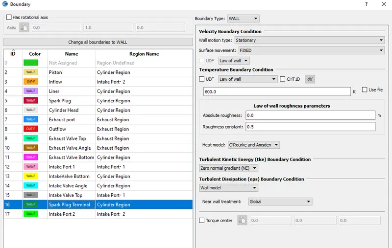
Intake Port 2:
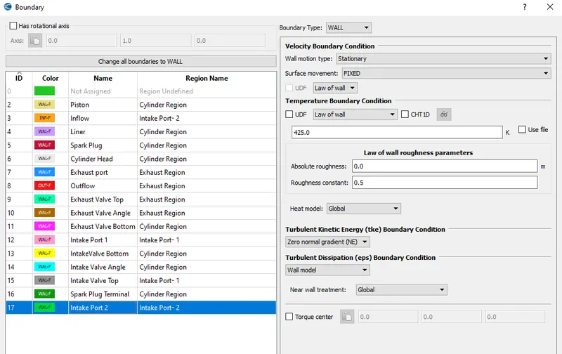
Physical Modelling:
Spray modelling:
CONVERGE has two types of liquid injection parameters: nozzles and injectors. An injector is a group of nozzles. In CONVERGE you can set up local coordinate systems, which help you intuitively configure and manipulate the geometry of the nozzles within an injector. In applications such as internal combustion engines, the fuel spray initiates, propagates, and dissipates very quickly and on a very small spatial scale. To dynamically capture the important physics of the injection process, you need a high-density grid around the spray.
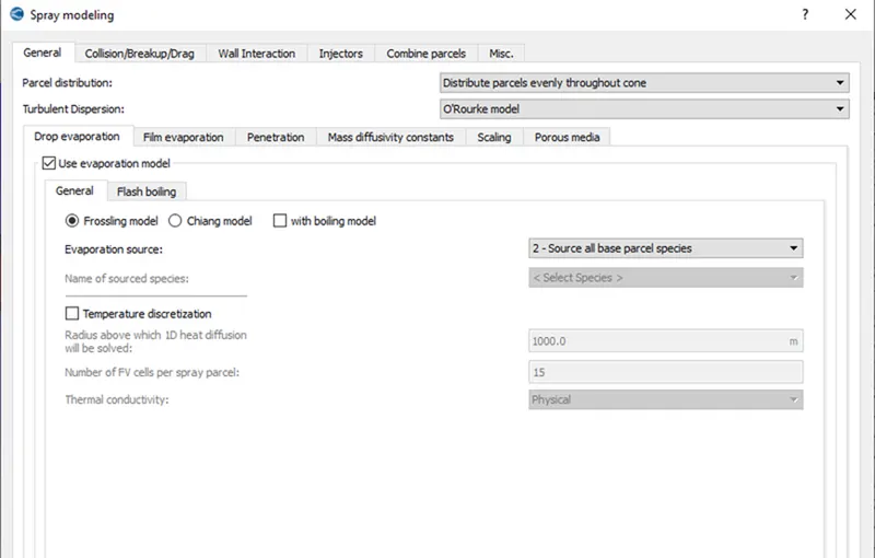
The following case settings are used to set up the spray modelling in converge.
General Setup:
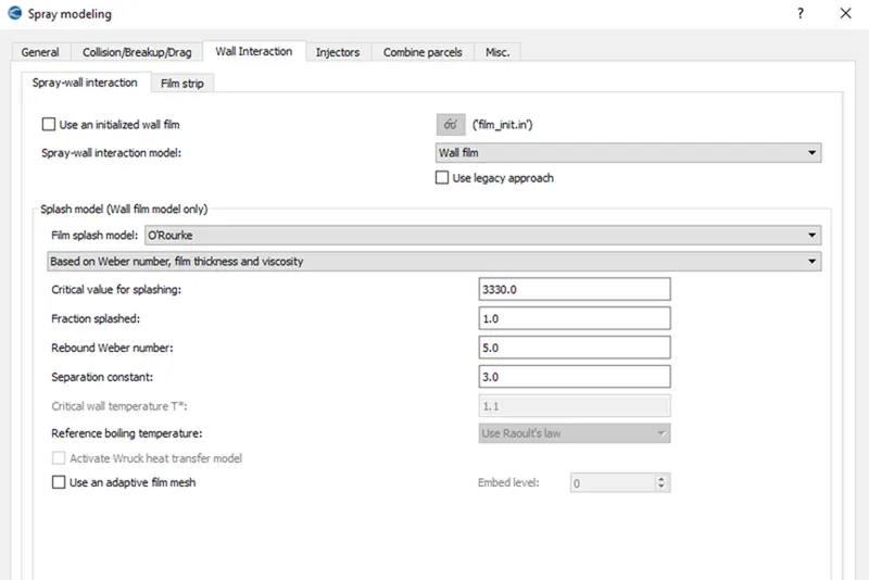
Wall Interaction:
Injector modelling:
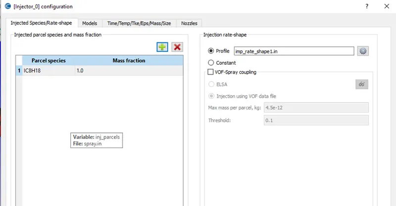
(i) Species:IC8H18 is the selected fuel in this calculation.
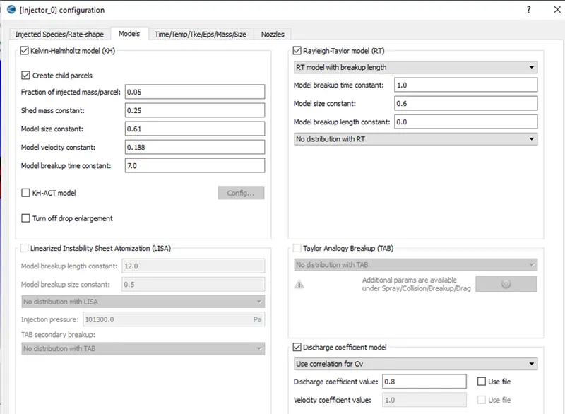
(ii)Models: Kelvin- Helmholtz model and Rayleigh- Taylor Model are used with all the default values.
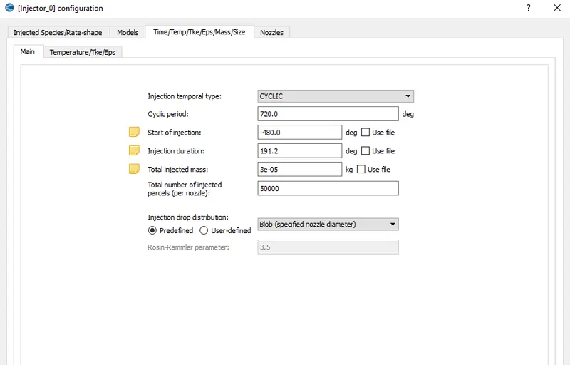
(iii) Configuration:
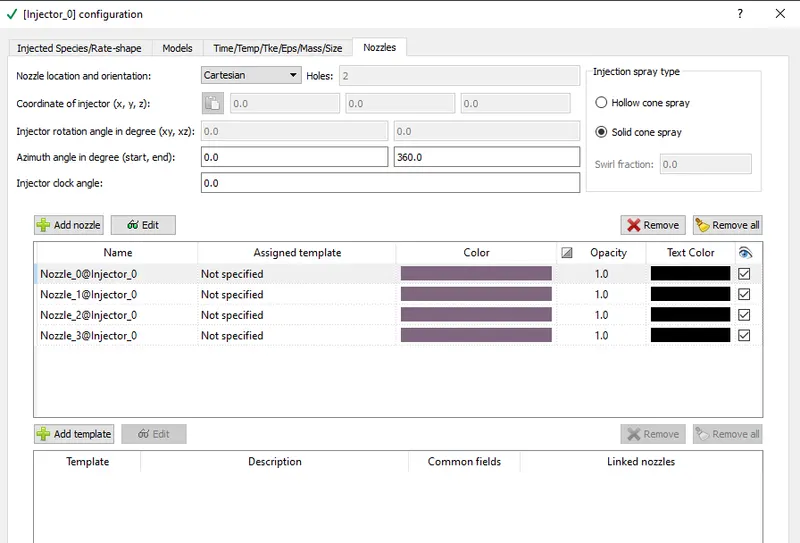
(iv)Nozzles:
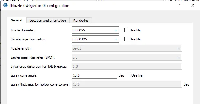
Nozzle diameter = 250 micro-meter
Circular injection radius = Nozzle radius
Spray cone angle = 10
- Nozzle 0
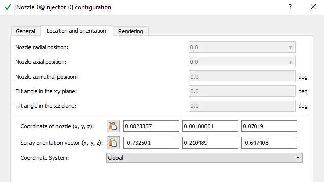
- center 0.0823357 0.00100001 0.07019
- Align Vector -0.732501 0.210489 -0.647408
- Nozzle 1
- center 0.0823357 -0.00099999 0.07019
- Align Vector -0.732501 -0.210489 -0.647408
- Nozzle 2
- center 0.0823357 -0.0004 0.07019
- Align Vector -0.5 -0.2 -0.647408
- Nozzle 3
- center 0.0823357 0.0003 0.07019
- Align Vector -0.5 0.2 -0.647408
Nozzle 0 values:
Location:
Combustion Modelling:
SAGE detailed chemistry solver is widely used for the IC engine calculations and similar is used in this case also. The SAGE chemistry solver parameters are shown below-
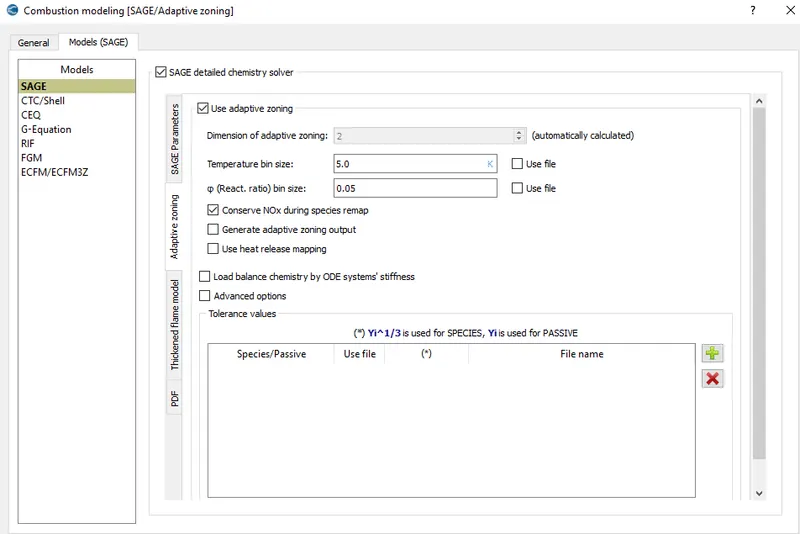
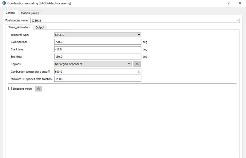
General settings used are shown below-
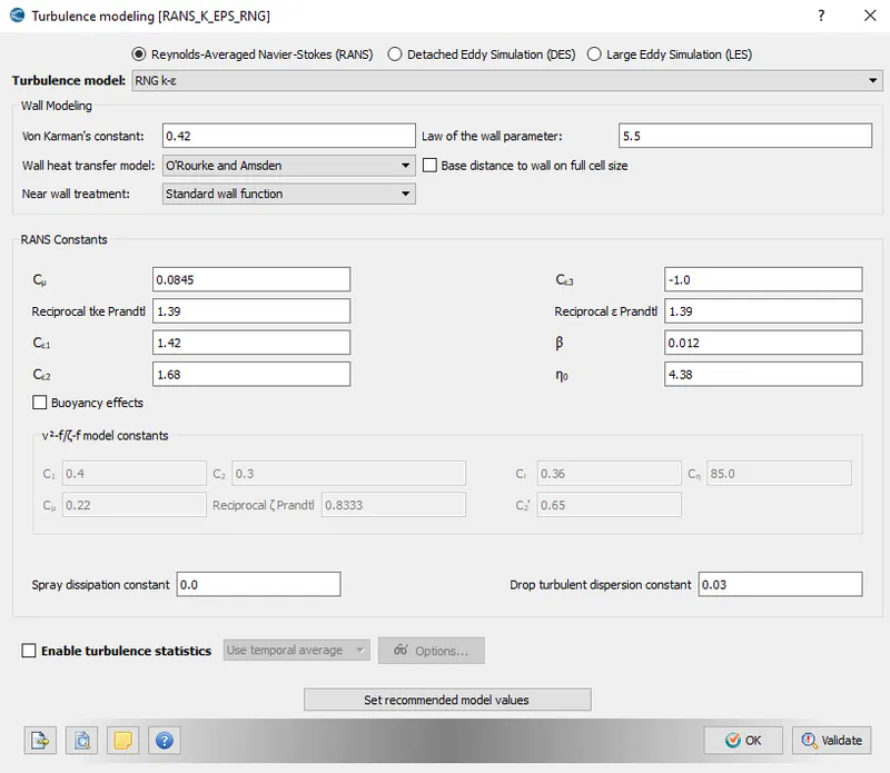
For turbulence modelling RNG`k-epsilon`model is used.
Spark Plug Modelling:
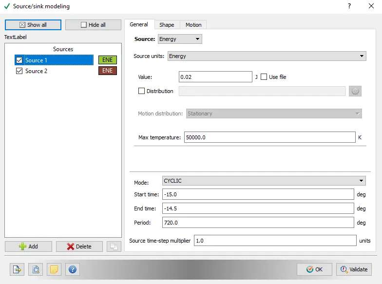
In order to initiate the spark for combustion spark plug is an important component for this and needs to be modelled. Below shown are the parameters for the spark initiation
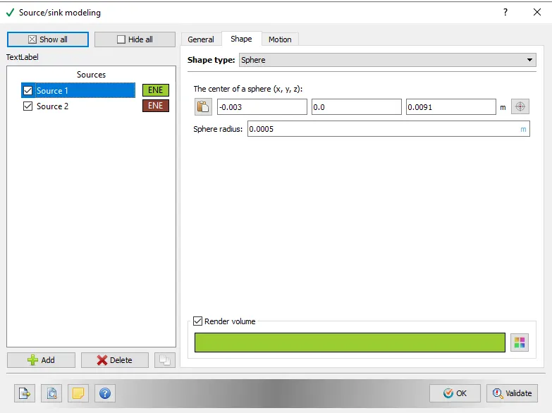
The dimesions are given as
Meshing:
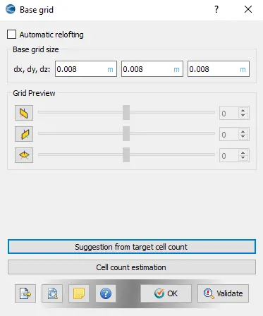
A 8mm mesh size is applied on the whole geometry with Adaptive mesh refinement and Fixed embedding at the required places.
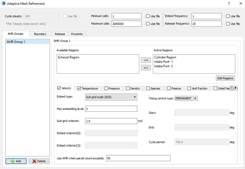
Adaptive mesh refinement is given with 3 level of embedding as shown below-
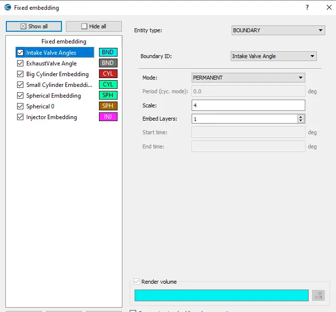
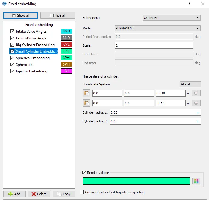
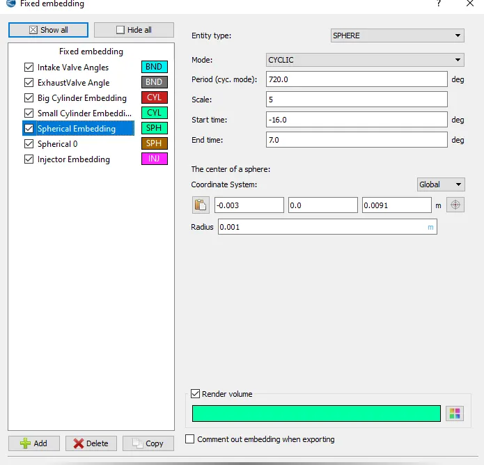
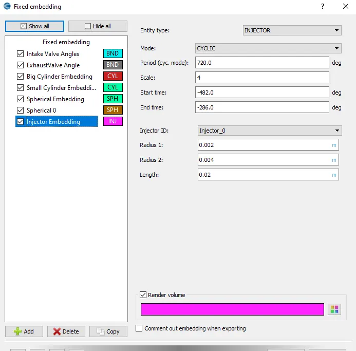
Fixed embedding is used of different shapes and some of them are shown below-
Injector embedding-
Simulation is submitted to solve by using the Cygwin terminal.
Results and Discussion:
After post processing the results from the simulation a certain amount of data can be accessed for further knowledge.
(a) Compression ratio: The volume plot can be used to idetify the compression ratio achieved during the simulation as the ratio of maximum and minimum volume during the whole cycle.
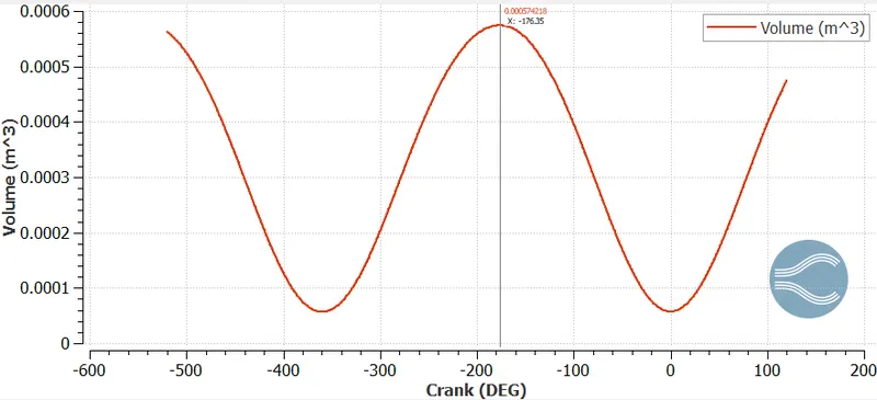
Maximum Cylinder Volume = `5.74218 * 10^(-4) m^3`
Minimum Cylinder Volume = `5.7391*10^(-5)m^3`
Compression Ratio = 10
(b) Combustion Efficiency of engine:
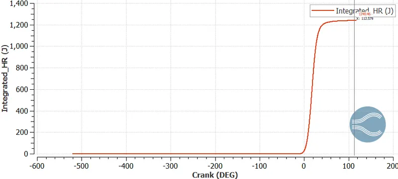
From the above plot,
Integrated heat mass release = 1240.46 J
mass of fuel = `m_f = 3*10^(-5) kg`
LHV = 43.4 MJ/Kg
`eta_(Combustion)=(IHM)/(m_f*LHV)`
`eta_(Combustion)=95.3%`
(c) Power and Torque calculation:
Various paramters are extracted from the engine performance calculator.
Work = 468.64 Nm
Duration = 240.2 degree
RPM = 3000
Power = Work / sec = 34.995 KW
Also, `P = 2*pi*N*T`
we get, T = 112.55 Nm.
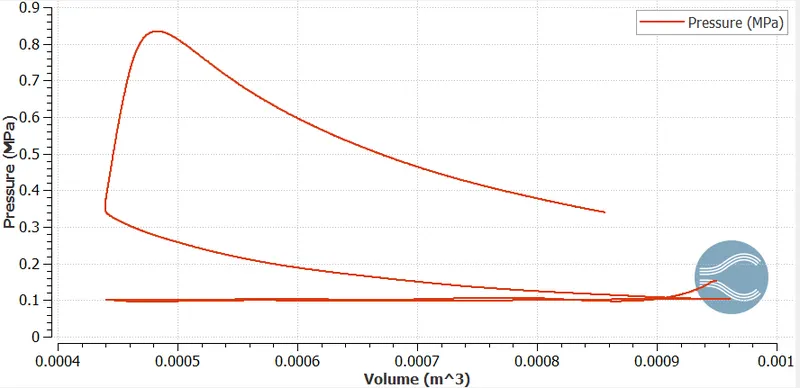
Work done can also be claculated by using the above PV plot.
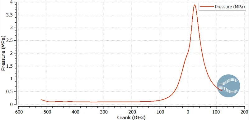
(d) Pressure Plot: The below shown image shows the variation of pressure during the crank movement. The sudden drift in the increasing peak symbolises the begining of combustion inside cylinder.
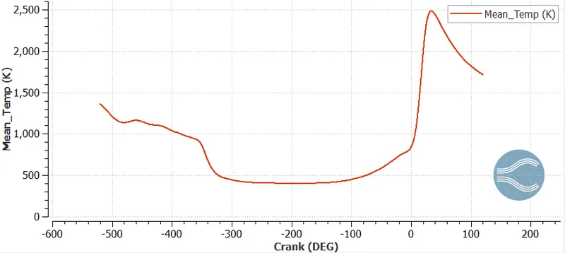
(e) Temperature Plot: The plot shows the variation in the temperature and peak temperature reached during the combustion.
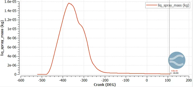
(f) Trapped mass in injector: The amount of fuel traped at the end of each cycle is clearly vivible from the following plot. And nearly 1/3 of fuel gets trapped.
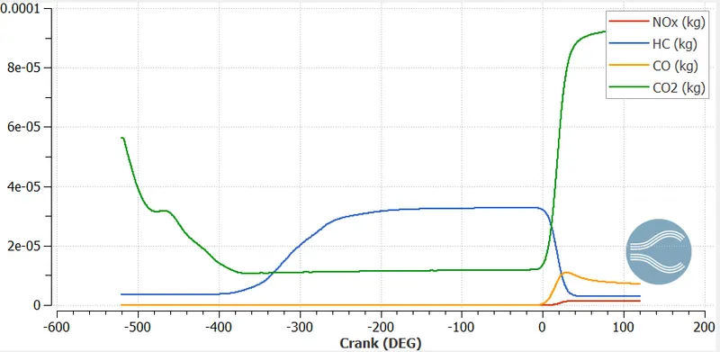
(g) Emssions: The emissions plot is shown below
(h) Why do we need a wall heat transfer model? Why can't we predict the wall temperature from the CFD simulation?
Since combustion is a multiphase phenomenon and it leads to enormous amount of heat generation. The heat transfer occurs inside a IC Engine by various modes conduction, convection and radiation along with various other systems i.e. cooling, Intake & Exhaust ports etc. Due to complexity of the heat transfer penomenon occuring inside there is sure need of specific model and thus a heat transfer model is taken in use.
For carrying out any specific CFD simulation wall temperatures in the form of boundary conditions are required. And those boundaries are considered to be constant throughout the calculation and it can also lead to altered results of temperatures.
(i) What is the significane of ca10, ca50 and ca90?
CA10, CA50, and CA90 defined as the crank angles of 10%, 50%, and 90% of the max accumulated apparent heat release. CA10 defines the begining of ignition and CA50 tells about the end of ignition. SO if the difference between the two is larger, larger is the duration of combustion and vice-versa.
Animations:
(a) Mesh motion:
Mesh motion is similar of the No hydro case
(b) Temperature Animation:
The overall temperature variation is shown below-
(c) Temperature Animation in mid plane:
(d) Velocity Animation:
Conclusions:
This simulation is set up in the converge software for the IC engine process. various modelling aramters are defined together in order to define a complete combustion process. From the simulation following points can be taken-
Compression ratio -
Combustion Efficiency - 95.3%
Power - 34.995 KW
Torque - 112.55 Nm.
The simulations animations are also attached with the report.