Week 10 - MRF project
Introduction:
Moving Refrence Frame leads to a simulation that ha moving bodies (A fan in this case) to simulate the flow of fluid throufh the domain properly a moving refrence frame is used. This gives an accurate/reliable results. It is used with steady sate approach for rotating objects (a fan). A thin mesh is created around the moving object which rotates on the axis of the object. This is espicially a elegent approach which helps in complex computations.
In this challenge a multi-level meshing is used to create a mesh captueing a significant region.
Meshing:
 |
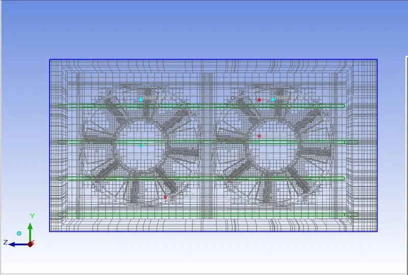 |
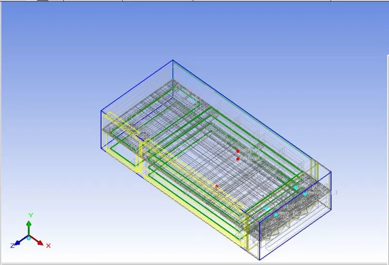
A fluid region is created inside the casing of the fan geometry and a multilevel of 3 is given to create the mesh.
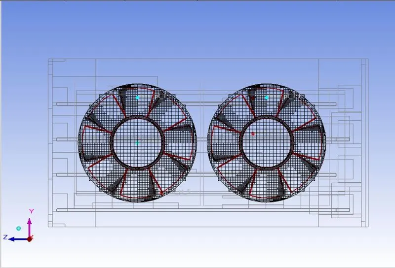 |
It can be seen a finer mesh at the leading edgo of the fan blade and coarser mesh at the trailing edge. This is a Multi-level meshing.
Furthet the setu is initiated in which the fluid zone is given appropriate condions (rpm=3000). This Boundary conditions help in getting appropriate results:
Results:
Residual Plots and Monitor points:
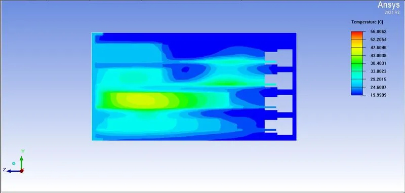
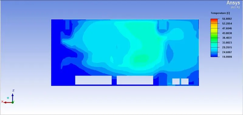
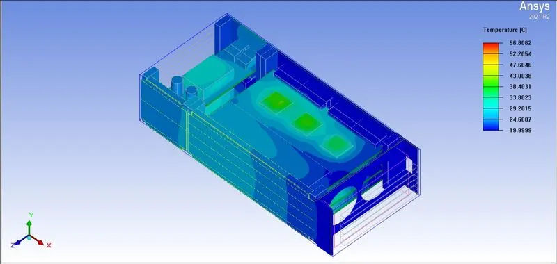
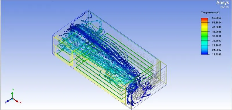
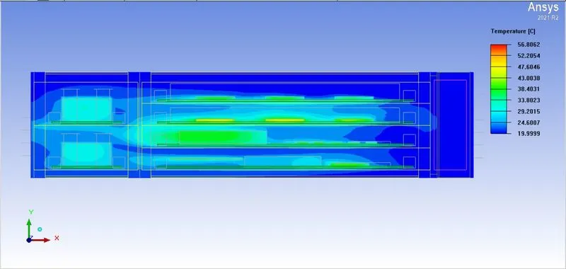
Contours
(Temperature)
 |
 |
 |
 |
 |
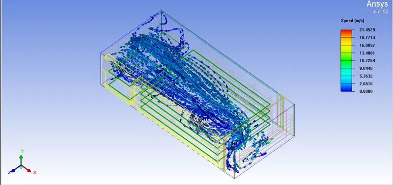
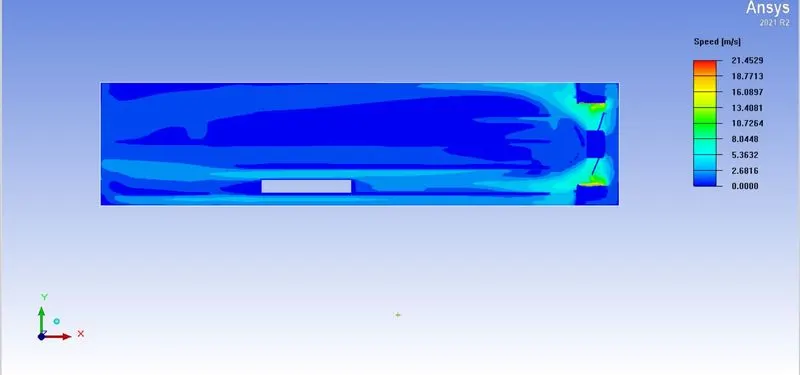
(Speed)
 |
 |
Conclusion:
Moving refrence frame method is perticularly useful when there is a moving part (Fan) this solves the problem of symplification of the components or replacing the component and gives a more reliable
result.