Week 10: Modeling and Simulation of flow around an Ahmed Body
Modeling and Simulation of flow around an Ahmed Body:
Objective:
- Create the CAD model using your any CAD package
- Setup a Coarse CFD simulation
- Setup the virtual wind tunnel as shown in the video
- Apply the right boundary conditions and solver settings
- Use a coarse mesh to demonstrate that your setup runs successfully.
- You need to show an animation of the velocity distribution on a cutplane. This cutplane should cut the ahmed body model in two symmetric pieces.
- You need to show an animation of the pressure distribution on a cutplane. This cutplane should cut the ahmed body model in two symmetric pieces.
- Post process the coarse mesh results and extract the x component of velocity along a line(Here, I am assuming that the normal of the intake boundary is along the +x direction)
- The line should be perpendicular to the ground plane.
Geometry Explaination:
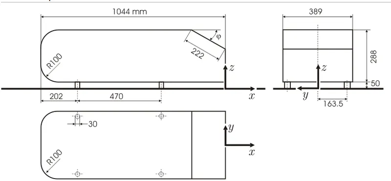
- Ahmed body created in CAD
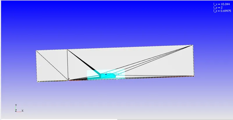
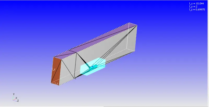
- A wind tunnel 10 times length of ahmed body is created. It is crucial to create wind tunnel of 25 times the size of body kept inside tunnel.
- Cut the geometry into half using ansys.
- Bottom of geometry is divided into two parts , free slip region ( before ahmed body) followed by law of wall boundary condition.
GEOMETRY
- Below is the dimensions of ahmed body
- Use CAD package to draw this geometry
- Geometry kept inside wind tunnel
- Dimension of wind tunnel can be seen at right-top corner
Simulation Parameters
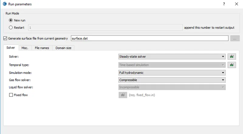
Run parameter
Simulation Time parameters
- Our simulation is a transient -state compressible solver.
- end time is 0.5
BOUNDARY LAYERS:-
Inlet
Outlet
Free-slip
Symmetry
Ahmed body legs
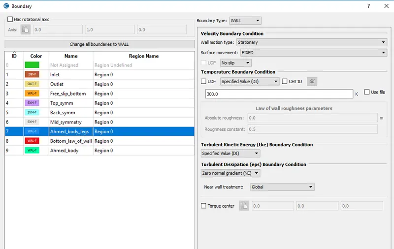
Ahmed Body
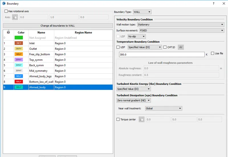
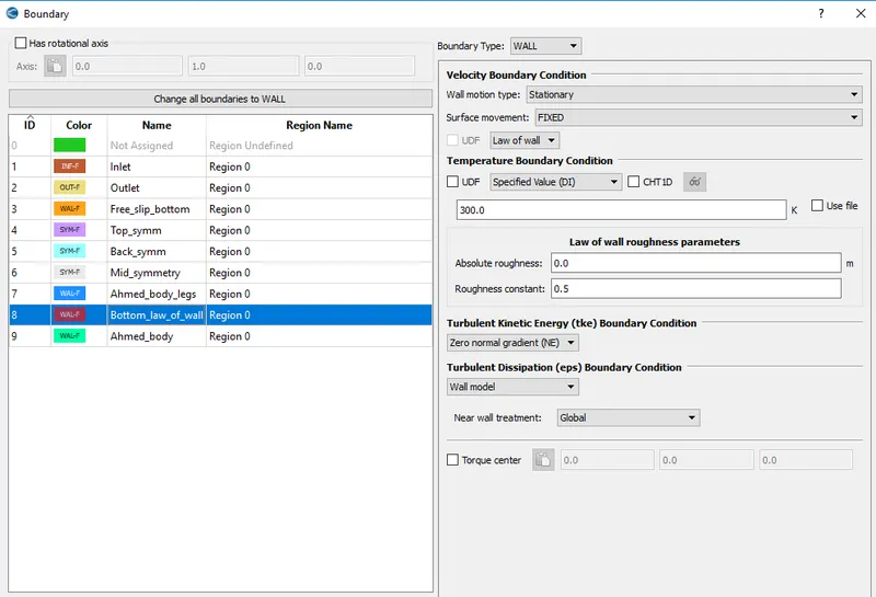
Ground surface
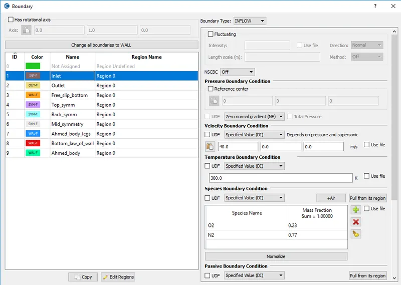
Inlet - Inflow boundary type is used, which is velocity inlet boundary condition which means velocity is specified and pressure is set to neumann boundary condition(pressure would be calculated). In wind tunnel test it is good for inlet velocity to be known.
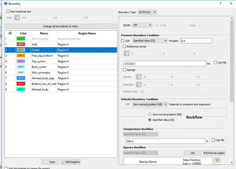
Outlet - Outflow boundary type is used, here pressure is specified and velocity needs to be calculated.
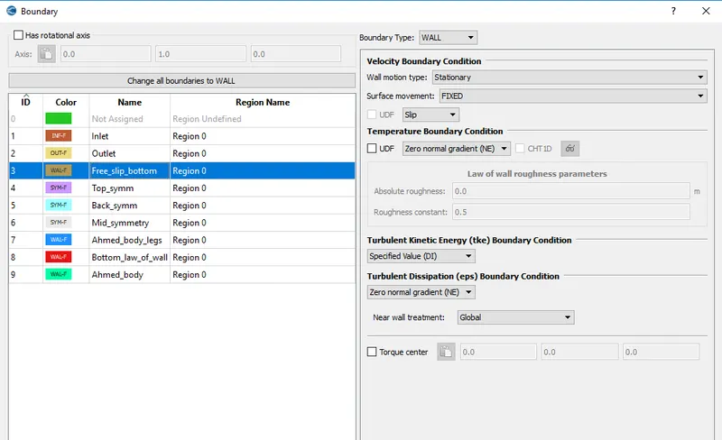
Free-slip bottom - This boundary condition is used to neglect or stop formation of velocity gradient. suppose when a car is moving , boundary layer is developed only on the surface of the car and not below the car(between car and ground). During actual wind tunnel test to stop formation of velocity gradient running belts are used between car body and ground and velocity of belt is set equal to velocity at inlet. In CFD this problem is overcome by providing free slip boundary condition, at free-slip condition no boundary layer is developed.
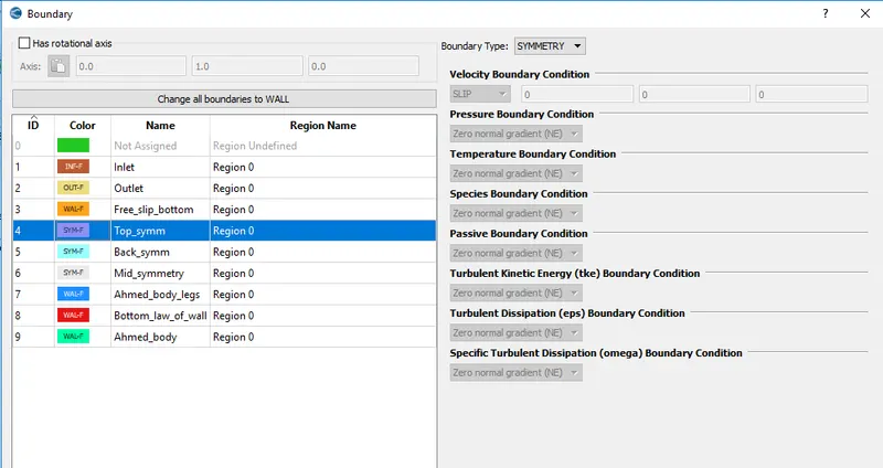
Symmetry - This boundary condition is used when flow conditions are symmetrical or involves repition to reduce size of computational domain.
Like in case of wind tunnel test , if you divide car into half both side of car would be facing similar flow condition , so in such condition to reduce computational domain symmetry boundary condition can be used.
Ahmed body & legs - They both have wall boundary type with no-slip boundary condition so that boundary layer is developed along its surfaces.
Regions and Initialisation
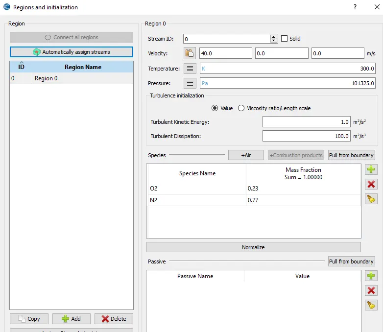
Fixed Embedding:
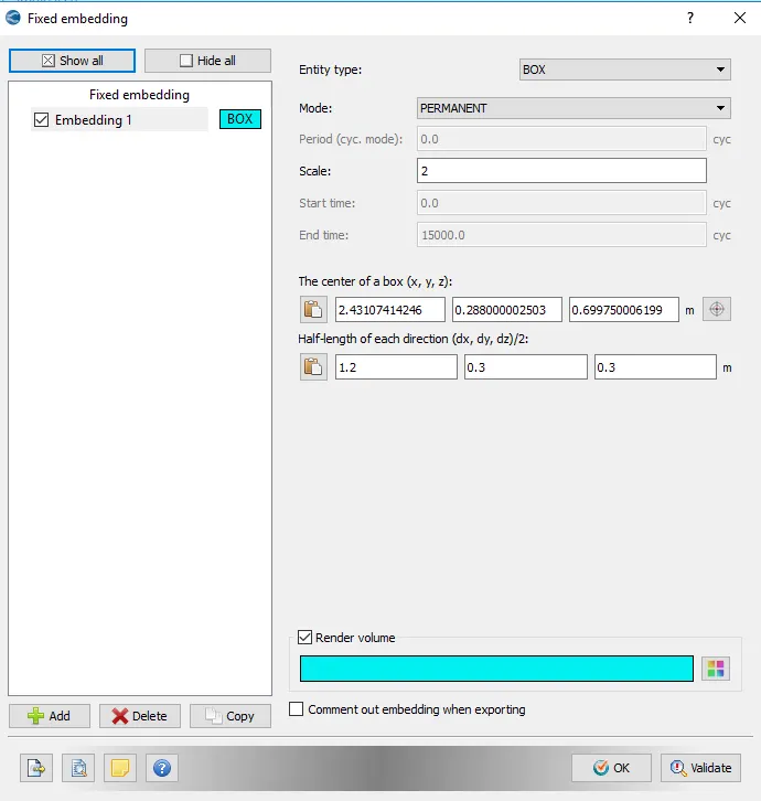
- Fixed embedding with 2 scale is used, here we have used box type embedding to create a volume embedding around ahmed body. A box shaped embedding is created to capture formation of boundary layer on and nearby ahmed body surface with help of finer grids.
Calculation of Reynold's number
Reynolds number = `(rhouL)/mu`
`rho` = 1.225 kg/`m^3`
u = 40 m/s
L = 0.278 m (height of ahmed body)
`mu = 1.789 times 10^-5 (kg)/(ms)`
So Reynolds number = 761,000
Calculation of free-slip region
It is going to be calculated by following formula , `delta = (0.382x)/R^(1/5)`
`delta = 0.003 m` (thickness of boundary layer)
x = free slip region
R = 761,000 reynolds number
hence x = 1.17m , distance of slip region from ahmed body is 0.4 + 1.17 + 2.5 = 4.07, here 2.5 is assumed length and 0.4 is length in front of ahmedbody where boundary layer starts developing, it is mentioned in video.
Steps to calculate DRAG FORCE
- Upload VTM file after post processing outputs on paraview.
- Go to 'filters' and search 'extract block' and select it and choose ahmed body
- In the pipeline block on LHS , choose ahmed body box.
- To extract surface , click on 'filters' serach extrat surface and then click apply
- to calculate drag force search calculators in filetrs and in attribute select cell type and change result array name to drag force and from scalars select pressure & normalX
- Now the drag force needs to be integrated over the netire surface , slect integrate variables from filters
- When you click apply , a sheet willl appear on RHS , in that change attribute to cell data.
- you can see drag froce in sheet on RHS.
Calculation of drag force
Drag force is the pressure force exerted by frontal area of moving object in direction opposite to motion of object. Drag force causes hindrance in smooth motion of vehicle and is directly related with design of vehicle body, poor design leads to high values of drag forces.
Drag force for the Ahmed Body is calculated using paraview which is -10.25 N (negative sign shows opposite direction of force from motion of vehicle)
Drag force = `1/2 rho*v^2CdA`
`rho` = 1.225kg/`m^3` density of air
A = 0.765 `m^2`
v = 40m/s
hence Cd = 2*drag force/`rho*A*v^2`
Cd = 0.0136 this is drag coefficient
Calculation of lift force
Lift force is the vertical force in the direction perpendicular to motion of vehicle, this force helps in generation of perpendicular thrust force which helps in areplanes to take off.
C lift = 2L/`rhoAv^2`
L = -133 N (lift force)
A = 0.765 `m^2`
v = 40m/s
hence C lift = 0.177 this is lift coefficient
Mesh Generation:
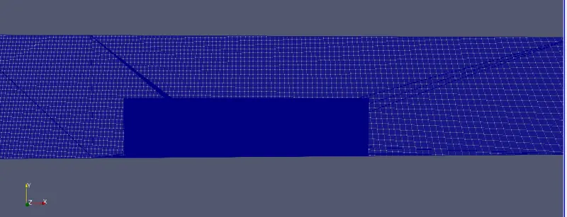
Velocity Contour:-
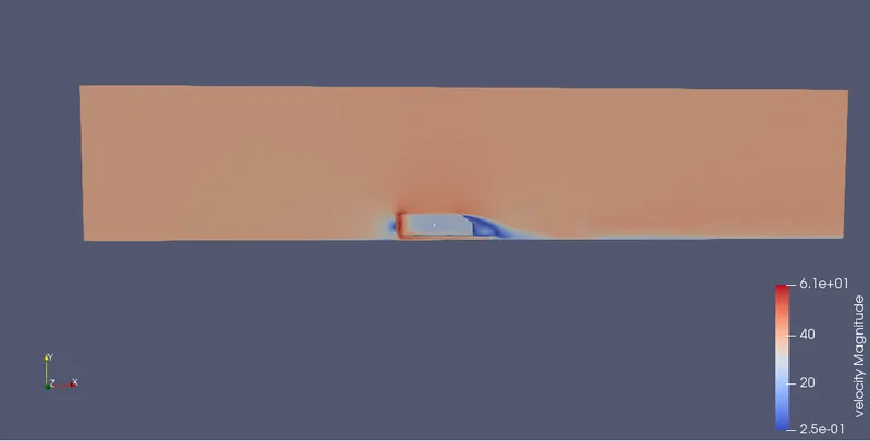
we can observe in the contour that there is sudden drop of velocity at back side of ahmed body , this is because of the design of geometry, vaccum space is created at the back side . Frontal area of the ahmed body sees rise in velocity.
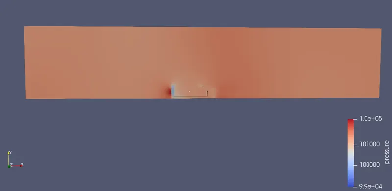
Pressure contour:-
Frontal section of body is highest pressure distribution while we can see a pressure drop at back end of the body.
Curved surface on front side also have low pressure value , it can occur because of curved design , air smoothly drags from the curved surface and hence pressure generation is reduced.
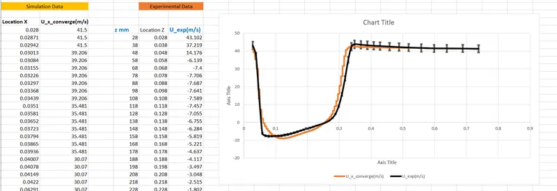
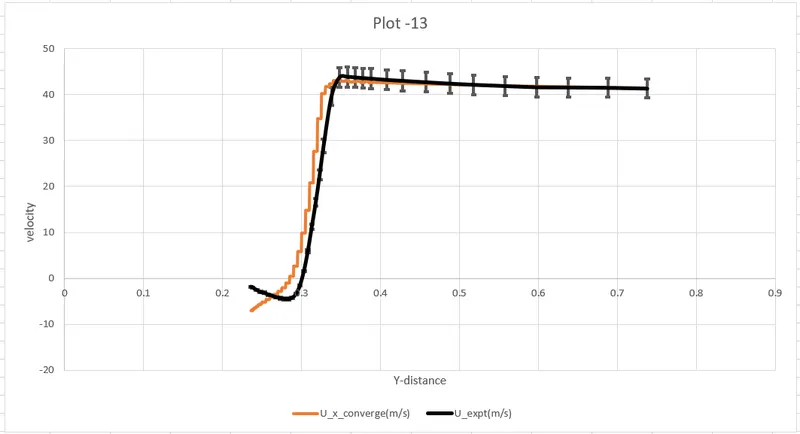
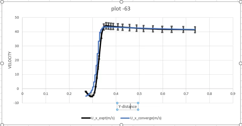
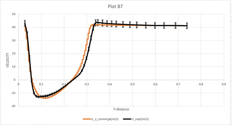
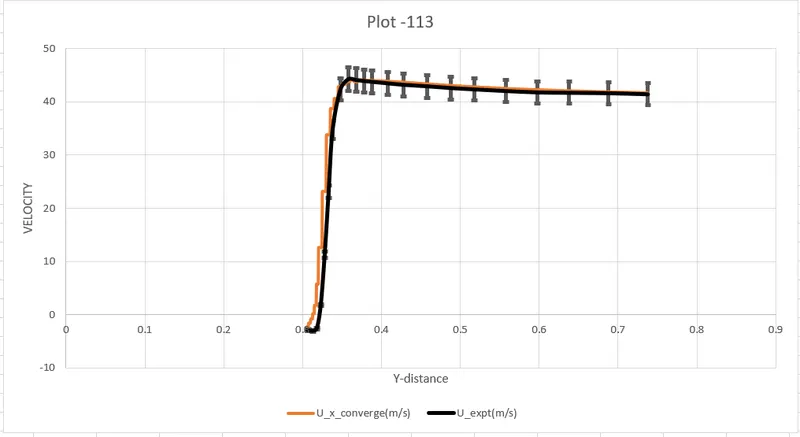
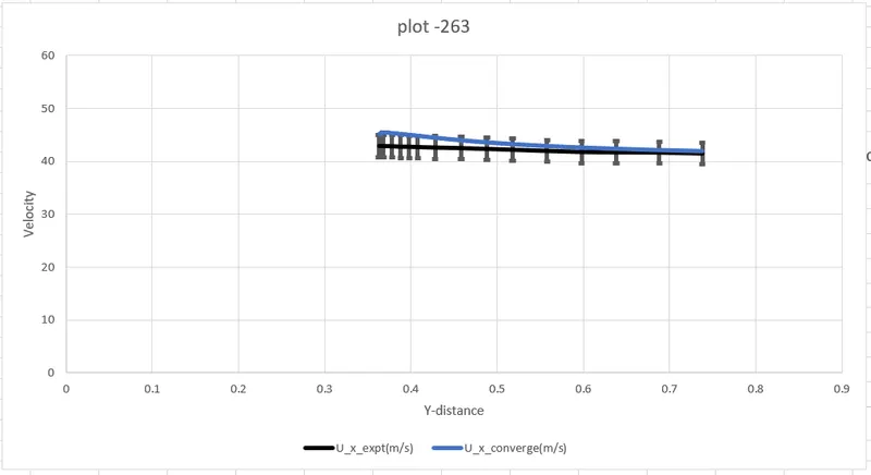
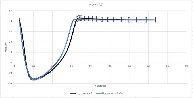
LINE PROBE Plots :
plot 37
Conclusions-
- Observed real time wind tunnel test, using ahmed body. It has given a sense how wind tunnel tests are done in automative industries.
- Given more clear viiew of how different boundary layer condition are used in different working condition.
- A new term free-slip was introduced , which plays a major role in CFD wind tunnel tests. Understood the effect and importance of free-slip region and how it is calculated.
- Pressure and velocity distribution on ahmed body surface.
- Calculation of drag and lift forces, these component are most important while designing an automobile.
- Comparison of simulation data with experimental data to observe variation of different parameters.
- Creating line probe plots for simulation and experimental datas.