Week 10 Challenge
Aim : To calculate the snow load on the bridge using following data.
Given data :
- The snow is settled snow
- Span of bridge is 10 m
- The deck of bridge is flat with β < 30°
- The depth of accumulation of snow is 1250 mm
Theory :
Generally the bridge structure is subjected to snow load, when the bridge is located in a snowy region or cold climatic countries.
- Snow load is calculated as per IS 875 part 4 and the loads are applied in accordance with IRC
- Minimum snow load is considered for design of bridges is 900 Kg/m3
Some of the snowy regions in India are Jammu and Kashmir, Himachal Pradesh, Haryana, Assam.
Calculation:
Depth of snow – 1.25m
Density of settled snow – 3 KN/m3
Flat deck β - 0°
Formula : Snow load, S° = density x area
= 3 x 10 x 1.25
Snow load, S° = 37.5 KN/m
Shape coefficient from I.S 875 part 4
For β < 30° , µ = 0.8
Design snow load, S = µ x S°
= 0.8 x 37.5
Design snow load, S = 30 KN/m
Aim : To prepare the model in a STAAD Pro and perform the analysis and justify with the results.
Theory : The general steps to be create a STAAD Pro model is given below,
Step 1 : Create the nodes by using the nodes cursor.
Step 2 : Joining the nodes by using the respective beam plate cursor.
Step 3 : Supports given to the nodes whether its pinned or fixed or any other custom supports
Step 4 : specifications given to the respective beams plates
Step 5 : Assign the dead load as per calculation
Step 6 : Save the model and perform the analysis
Step 7 : The results are obtained and discuss with the results
Step 8: Take the print out of report of necessary results.
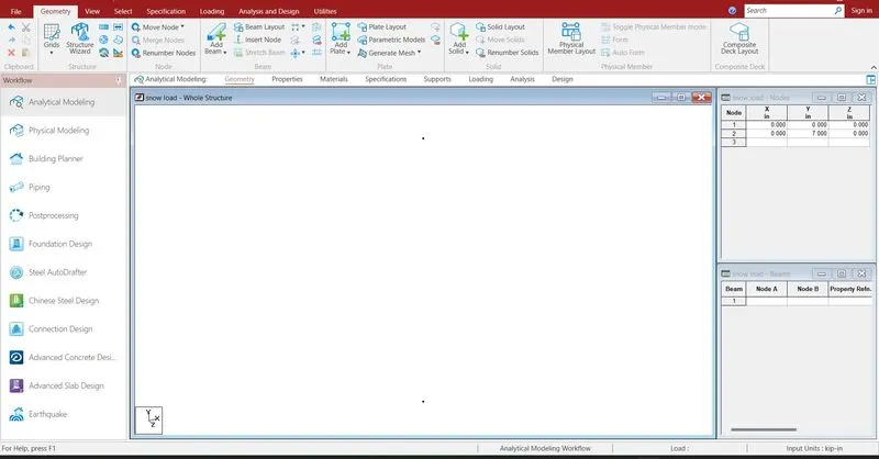
Creating the nodes by using node cursor.
Open the STAAD Pro window > Select > Node cursor > enter the value with respect to X Y Z axis > click enter
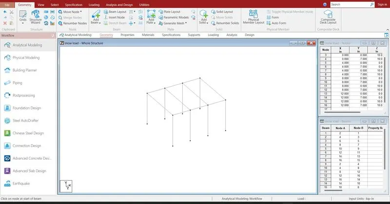
Join the nodes by using beam cursor.
Select > beam cursor > join by dragging the mouse or enter the node numbers > click enter
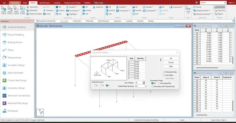
Deck slab are created by using nodes and plates cursor.
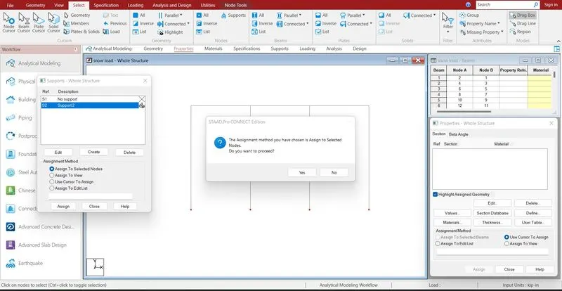
Supports are given to the respective nodes.
Specifications > Supports > select the supports > click enter
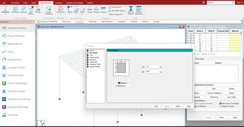
Defining the properties to the beam .
Specification > Prismatic > Rectangle > enter dimensions > select the beam > assign the properties to selected beams.
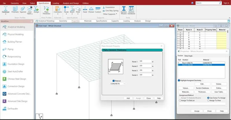
Defining the thickness to the plate.
Specification > plate thickness > enter dimensions > select the plates > assign the properties to selected plates.
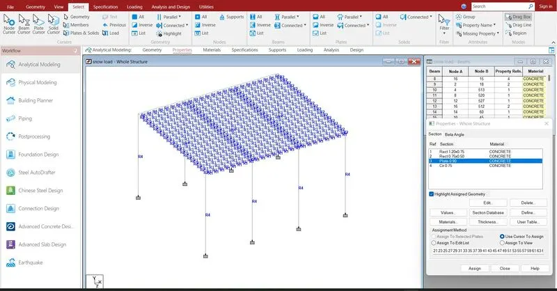
properties are assigned.
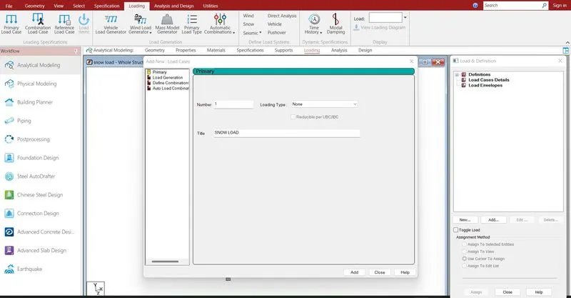
Defining the load cases .
Loading > Load case detail > select load > Add
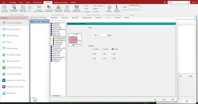
Add > plate load > enter the value > ok
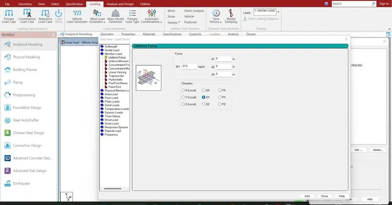
Loads are defined.
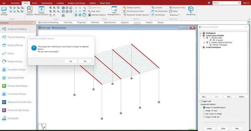
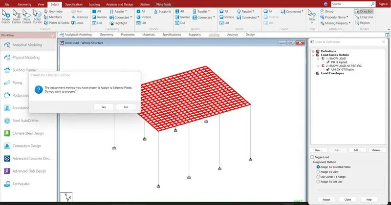
Select the defined load > select the beam/Plate > Assign to selected beam/plate > click enter
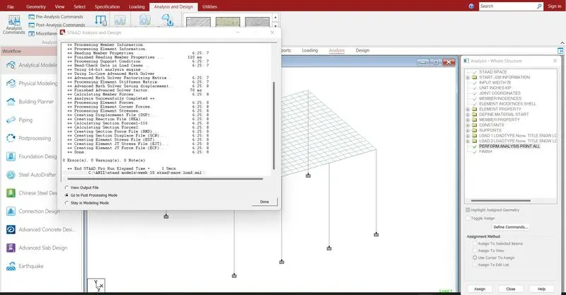
Run analysis > go to post processing mode > Results
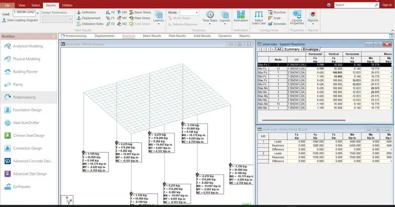
The reactions are generated at the end of the nodes .the reaction value is 1080 KN
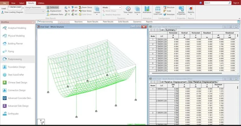
- The maximum deflection in X direction is 0.004 mm
- The minimum deflection in X direction is -0.004 mm
- The maximum deflection in Y direction is 0 mm
- The minimum deflection in Y direction is -8.97 mm
- The maximum deflection in Z direction is 0.015 mm
- The minimum deflection in Z direction is -0.015 mm
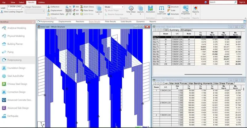
- The maximum shear force in X direction is 188.805 KN
- The minimum shear force in X direction is -2.774 KN
- The maximum shear force in Y direction is 79.407 KN
- The minimum shear force in Y direction is -79.401 KN
- The maximum shear force in Z direction is 12.83 KN
- The minimum shear force in Z direction is -12.833 KN
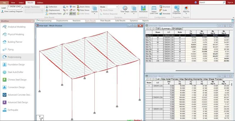
- The maximum bending moment in X direction is15.958 KN-m
- The minimum bending moment in X direction is -15.958 KN-m
- The maximum bending moment in Y direction is 60.257 KN-m
- The minimum bending moment in Y direction is -60257 KN-m
- The maximum bending moment in Z direction is 34.091 KN-m
- The minimum bending moment in Z direction is -42.046 KN-m
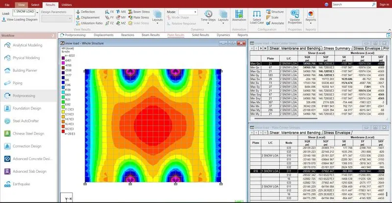
- The maximum shear stress in X direction is 326.496 KN/m2
- The minimum shear stress in X direction is 363 KN/m2
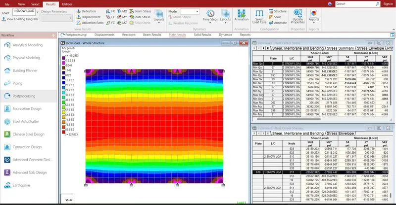
- The maximum shear stress in y direction is 7.801 KN/m2
- The minimum shear stress in y direction is 1097.4 KN/m2
- Reports are taken printout which ever is necessary by using report
- In the report option we obtain the results of section forces, displacement, reactions, plate
- The exact report is to be taken further move to design