Week 10 Challenge
1)
Aim: To calculate the total number of purlins and girts required for the building with the following inputs:
Rafter span = 50 m
Bay spacing = 8 m
Roof slope = 1 in 10
Height of column = 12 m
Brick wall height = 2 m
Purlin spacing = 1.2 m
Girt spacing = 1.5 m
Procedure:
Step 1: Determining Number of Purlin:
Given:
Rafter Span = 50 m.
Spacing of Purlin = 1.2 m.
Therefore, Half of the Span of the Rafter = 25 m.
Height of the Truss = 2.5 m (Using the given value of the slope)
Hence, Inclined length of the rafter = 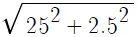 = 25.124 m
Now, since we know that Number of Purlin = (Inclined Length of Rafter/ Spacing of Purlin) + 1
= (25.124/1.2) + 1 = 22 ( round up nearest integer).
Hence, Total Number of Purlins on entire span of truss = 22 x 2 = 44.
Step 2: Calculation of number of Girts:
Given:
Column Height = 12 m.
Girt Spacing = 1.5 m.
Brick Wall Height = 2 m. [No Girts are required]
So, the Height of the column for which Girt is required = 12 - 2 = 10 m.
Therefore, Number of Girts on one side = (10/1.5) + 1 = 8
Hence, Total Number of Girts on both sides = 8 x 2 = 16
Result: Hence Total Number of Purlins required = 44 and the Total number of Girts required on both sides = 16.
2)
Aim: For the given loading, we need to taper the beam for the BMD envelope and check the utility ratio within the limit.
Given Staad File:
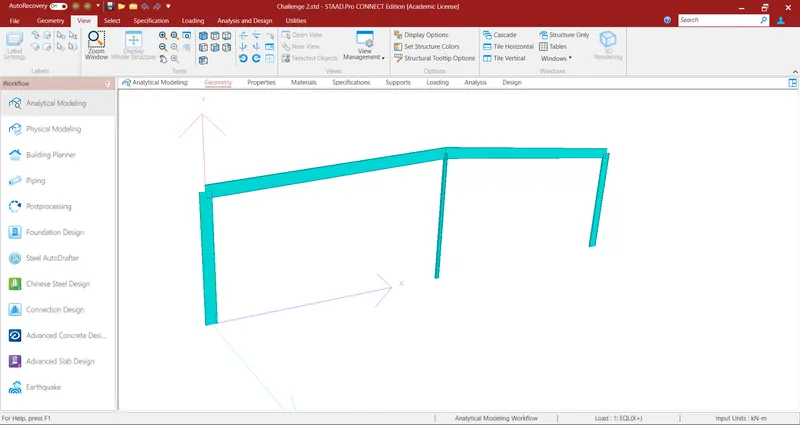
Procedure:
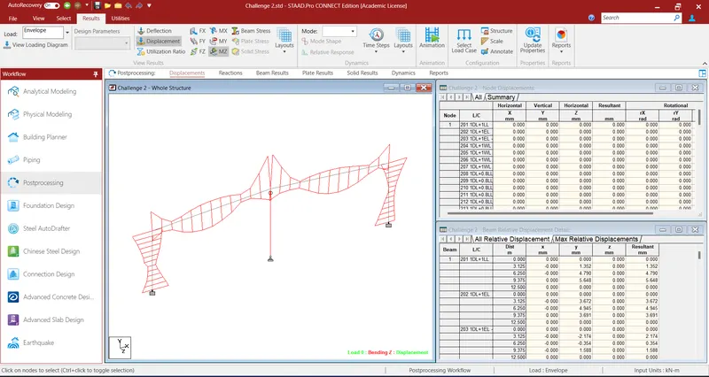
Step 1: Run this file and obtained post-processing results. Select Load as Envelelope as we wish to view the bending moment diagram due combination of loads.
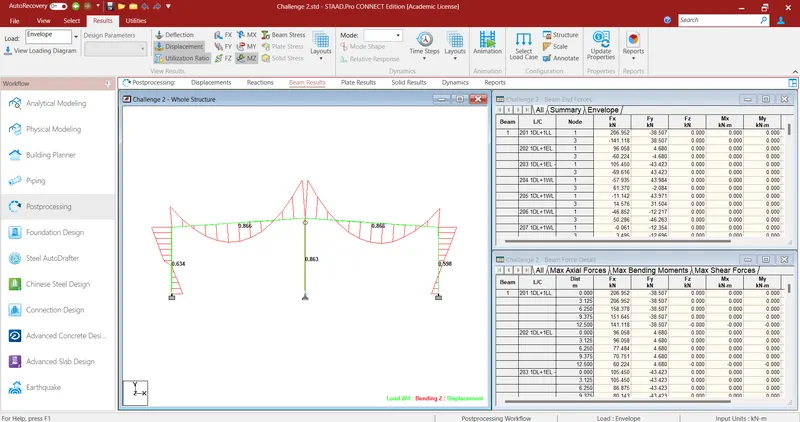
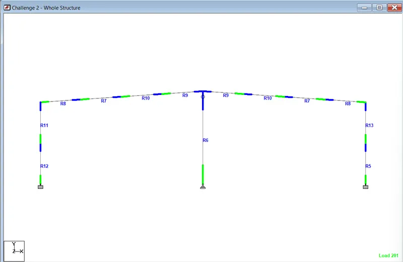
Step 2: The figure below represents the Utilisation ratio and Bending Moment diagram, now we will try to taper the section such that where the bending moment is not high, we will provide a section will a lesser moment of inertia, as for such part, lesser Moment of inertia is enough to resist the Load.
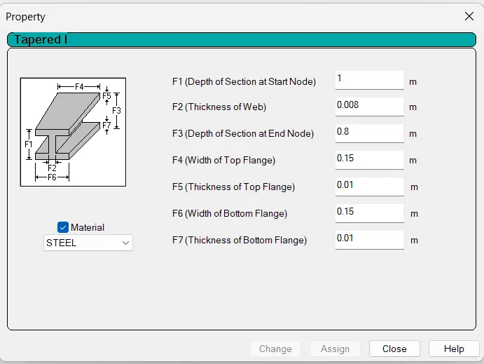
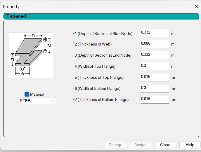
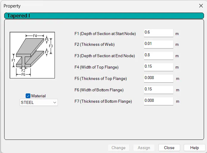
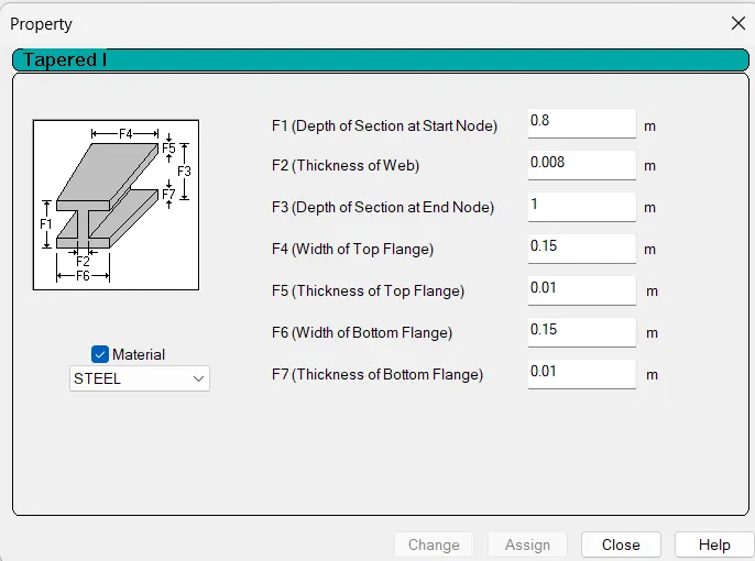
Step 3: Updated Dimensions of the frame are mentioned below:
For R5
For R6
For R7
For R8
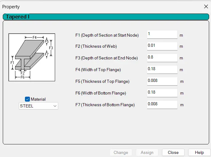
For R9
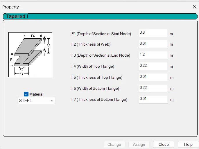
For R10
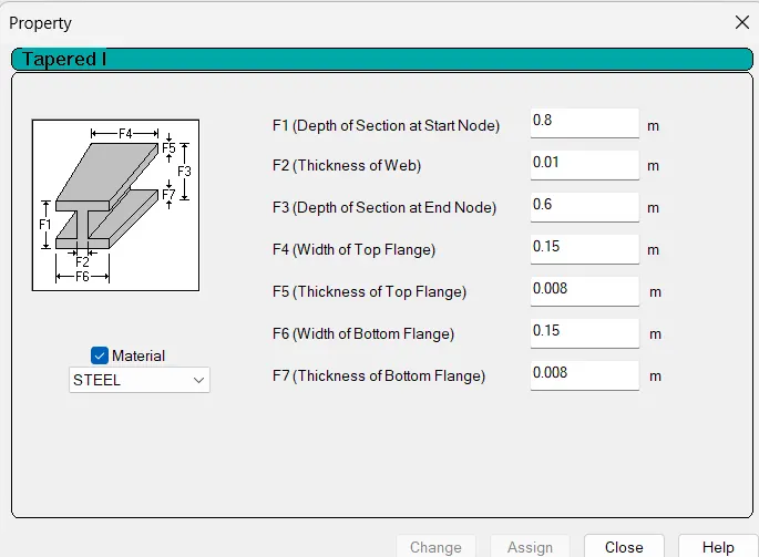
For R11
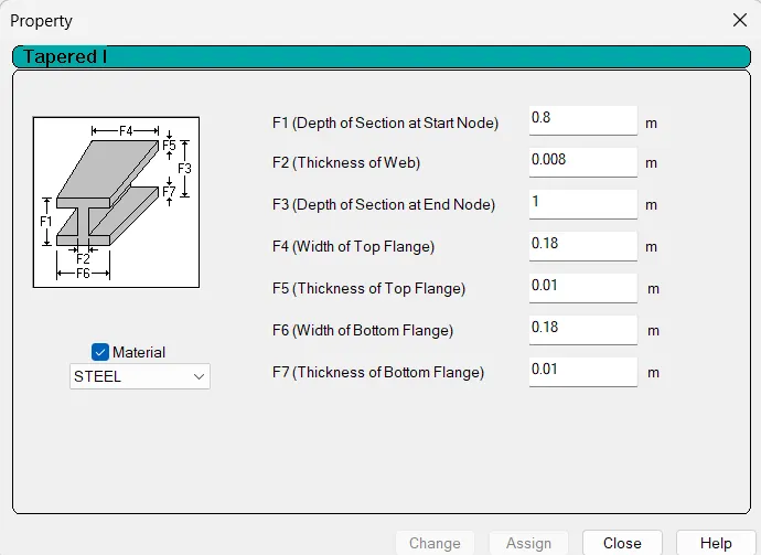
For R12
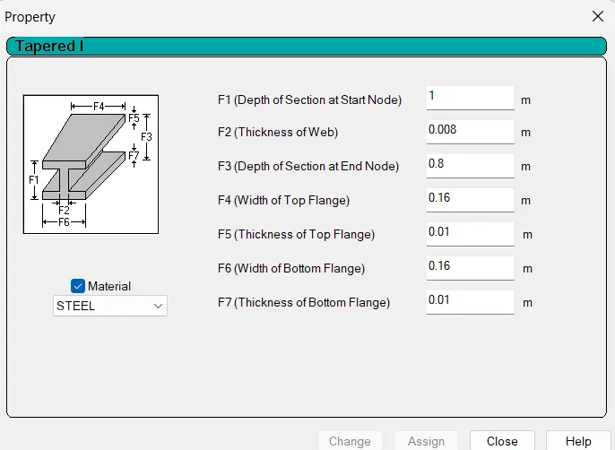
For R13
Step 4: After providing the appropriate tapered section, the final utilization ratio for the different members will be as shown in the below figure.
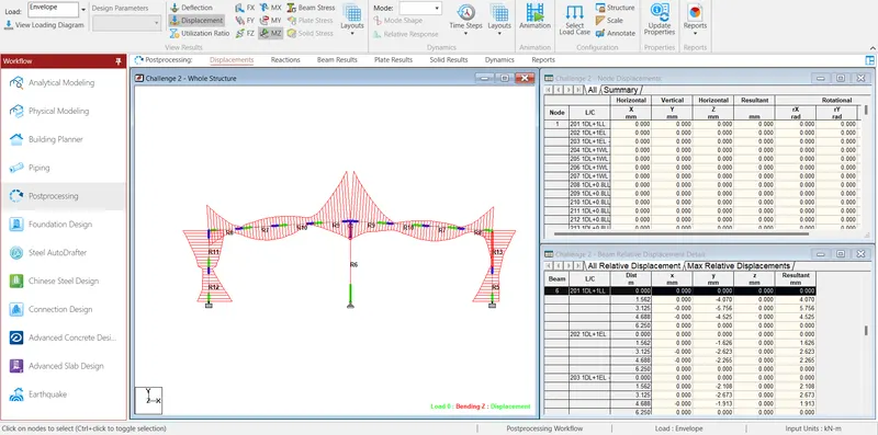
Result: For the Given Frame, tapered sections are used to reduce the steel use and tried to keep the utilization ratio within 0.65 to 0.95, for optimum result.
3)
Aim: To Determining Wind load for certain categories and conditions as per IS 875 Part 3:2015
Building Details:
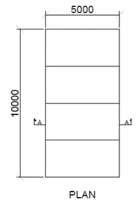
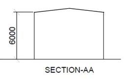
An Industrial building of plan dimension 10m x 5m is to be constructed (as in Figure below). The building is situated in Chennai.
Assume wall opening as 15 %.
Bay spacing = 2.5m.
Procedure:
For the Calculation of Wind Speed, we will refer to IS 875 Part-3.
As per IS 875 Part-3, Clause 5.2
Basic Wind Speed, Vb = 50m/s
Since, Design Wind Speed, Vz = Vb.K1.K2.K3.K4
Values of K1, K2, K3, and K4 as per IS 875 Part-3 are 1, 0.91, 1.0, and 1.15 respectively.
Hence, Design Wind Speed = 52.33 m/s.
Since, Wind Pressure Pz = 0.6x(Vz)2 where Pz = Wind Pressure in N/m2 = 1.64 kN/m2
Therefore, Pz = 1643.06 N/m2 = 1.64 kN/m2.
Now, Design Wind Pressure Pz = Kd.Ka.Kc.Pz
As per IS 875 Part-3, values of Kd, Ka, and Kc are 1.0, 0.9, and 0.8 respectively.
Therefore, Pd = 1.181 kN/m2.
Now, Wind Load acting in a direction normal to the individual structural element or cladding unit F =  is internal pressure coefficient = 0.5 for the opening of 15% of wall area i.e. medium permeability (as per clause 6.2.2 of IS:875, part 3.
External pressure coefficient:
l= 10 m ; b = 5 m ; h = 6 m
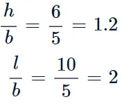
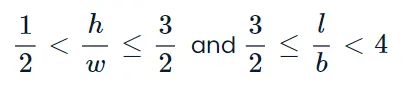
Thus as per table 5 of clause 6.2.3.1 of IS:875, Part 3
|
Wind angle (θ) |
Cpe |
Cpe |
Cpe |
Cpe |
|
Wall A |
Wall B |
Wall C |
Wall DF | |
| ° | +0.7 | -0.3 | -0.7 | -0.7 |
| 90° | -0.5 | -0.5 | +0.7 | -0.1 |
Case 1: θ = 0°
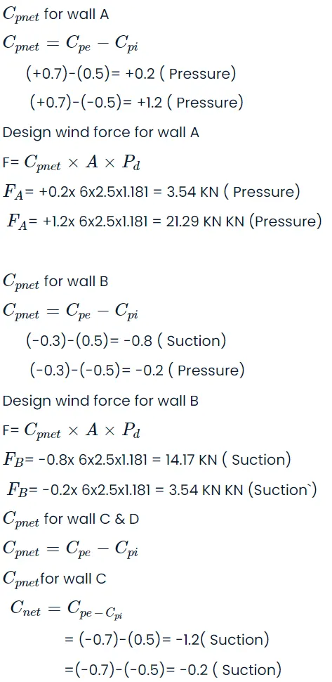
Design wind force for walls C & D
Fc = -1.2 x 30 x 1.181 = 42.516 kN (Suction)
Fd = -0.2 x 30 x 1.181 = 7.09 kN (Suction)
Case 2: θ = 90°
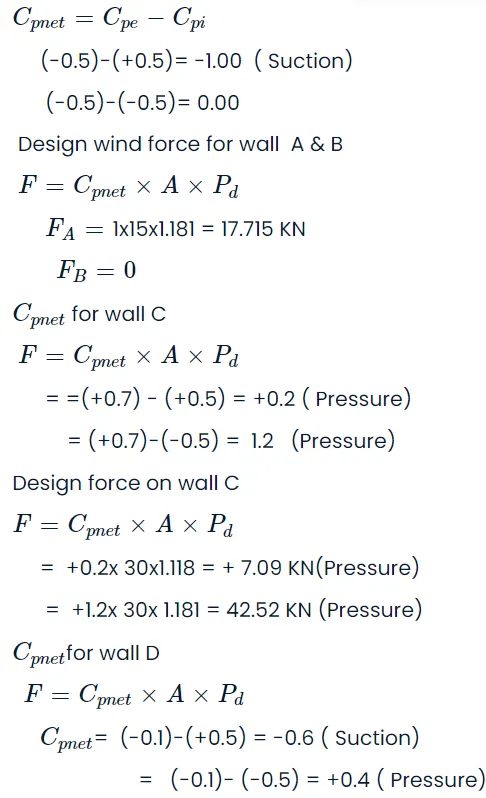
FD = -0.6 x 30 x 1.181 = 21.26 kN (Suction)
Fd = 0.4 x 30 x 1.181 = 14.17 kN (Pressure)
Maximum Pressure for design = 42.52 kN
Cpe for a pitched roof for rectangular clad building as per table-6 clause 6.2.3.2 of IS: 875 Part-3
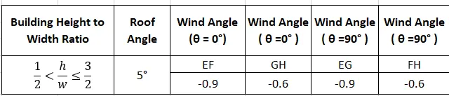
A= surface area of a structural element or cladding unit
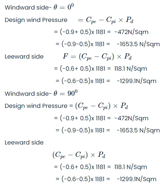
Maximum uplift pressure = - 1653.5 N/m2
Result: The maximum pressure on Wall is found to be 42.52 kN.
4)
Aim: To find support reaction for a given load on the Mono sloped structure (20 degrees) of width 10 m & length 30 m with a bay spacing of 6 m having no wall sheeting (fully open all around) has following loads.
Given:
Self Weight factor – 1.1
Roof Sheet loading = 0.5 kN/m2
Purlin load = 6 kN/m2
Live Load on Roof = 1.5 kN/m2
Wind Load on rafter (Pressure) = 2 kN/m2
Assume column height = 5 m.
Mid-height of roof = 5 x tan20 = 1.81 m
Procedure:
Step 1: Create a new staad pro file and create the basic model, as per the given data. Add Supports.
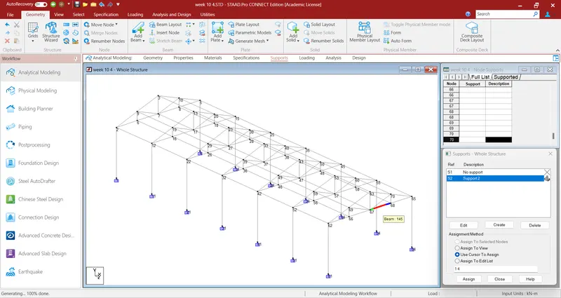
Step 2: Now Apply all loads including Self-Weight.
Total Dead load = 6 + 0.5 = 6.5 KN/m^2 = 6.5 x 6 = 39 KN/m.
Live load = 1.5 KN/m^2 = 1.5 x 6 = 9.0KN/m.
Wind load = 2 KN/m^2 = 2 x 6 = 12 KN/m.
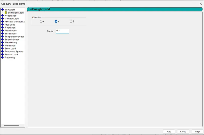
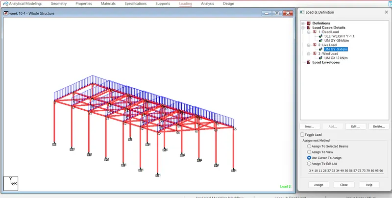
Step 3: Add material properties. and run the analysis.
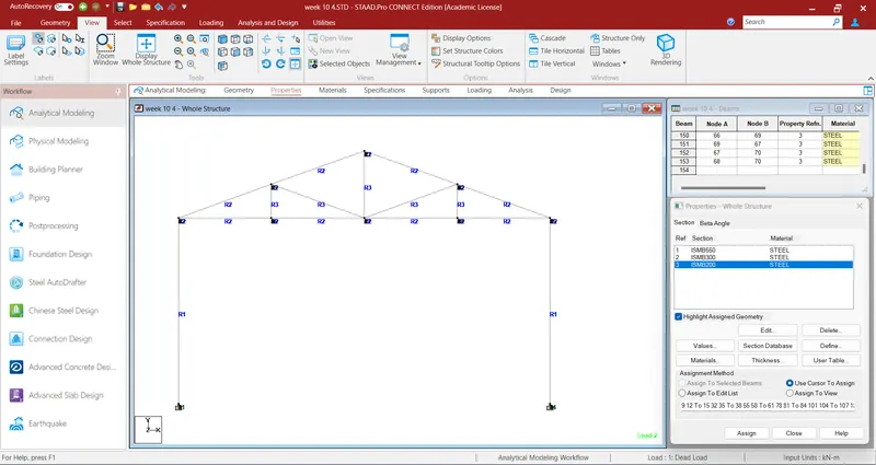
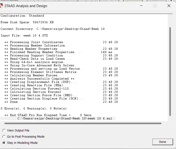
Step 4: Go to the post-processing tool and display the support reactions.
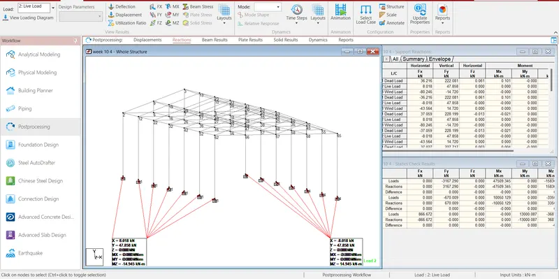
Step 5: Now, go to the output file, under Utilities Tab, and see the net reaction on structure for all the loading cases.
Net Support Reactions for each loading case are given below.
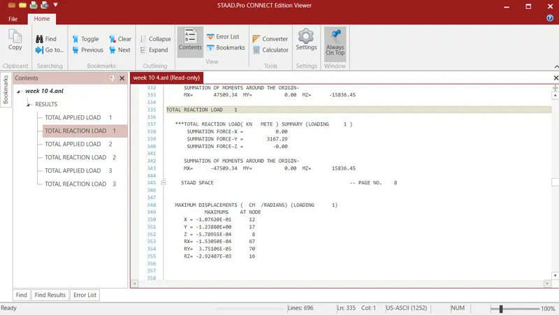
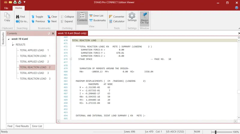
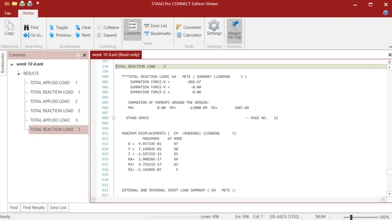
Result: Model is prepared as per the given dimension and data, loading is applied on the modeled structure and Support reaction has been found out successfully.