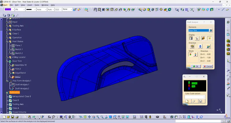
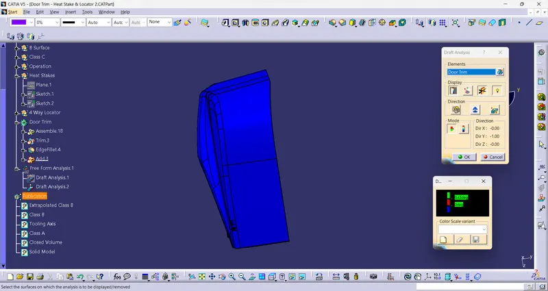
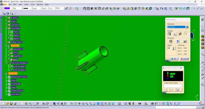
Week 10 - Challenge 3 - Door Trim Lower with Engineering Features
Aim:
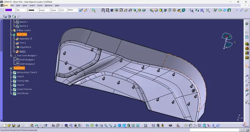
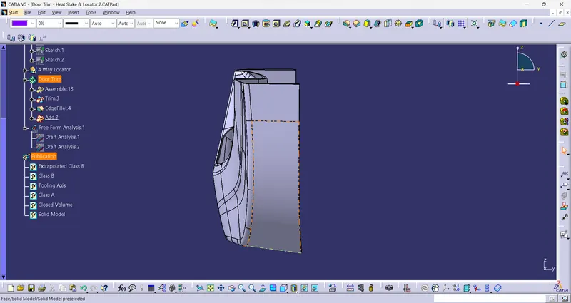
To Create the Door Trim Lower Plastic component with the Heat Stakes and the locators considering the design rules for the door applique through the given Class-A surface.
Heat stakes
Heat stakes are the extension from the class B surface of plastic component.They are mainly used for assembly purpose. for this asssemly heating method is used. Heat is provided to the heat stakes and it melts and form solid shape over the othe component after cooling.
Locators:
Locators help to restrict the degree of freedom of component. there are two types of locator: 1. 4 Way Locator, 2. 2 Way Locator.
Input:
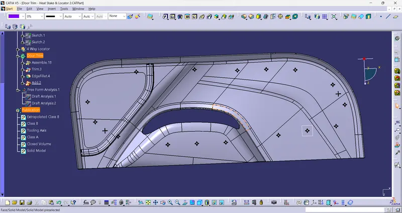
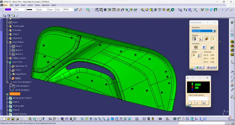
For this project, a Class A surface with 16 points for heat stakes are provided as input.
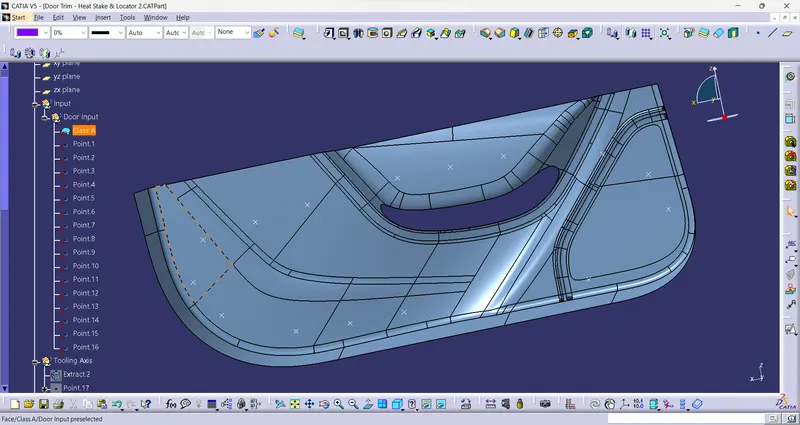
Tooling Axis:
Tooling axis shows the direction in which mold moves. To define a tooling axis, firstly need to find a view/direction in which complete class A surface is visible (along with the side parallel to direction).
So, for this given surface of door trim, tooling axis can be formed in Y direction.
find a flat face and take a point on the surface and created a line with help of point and direction.
This line is the Tooling axis for the given Class A Surface.
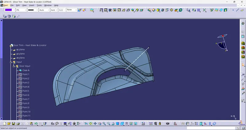
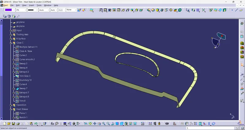
To Convert the given Class A into Solid model, Class B and Class C surface need be created.
Class B surface:
To create the Class B surface, the class A surface is offsetted at a dist of 2.5 mm. Due to this, some filletd are not produce and gaps were created To fill these gaps the edges are extracted and using multi section solid the gaps are filled.
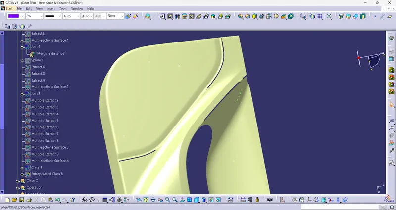
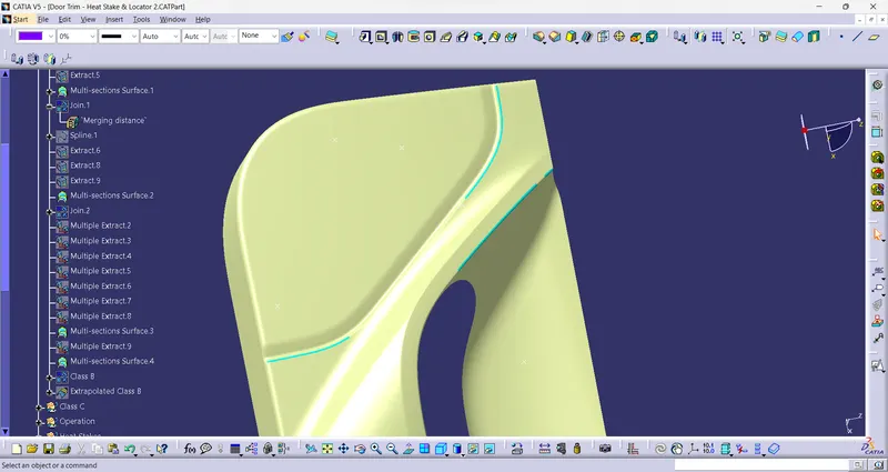
Final Class B surface:
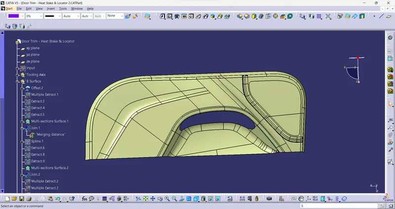
 edges.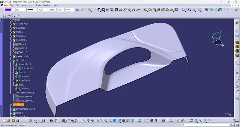
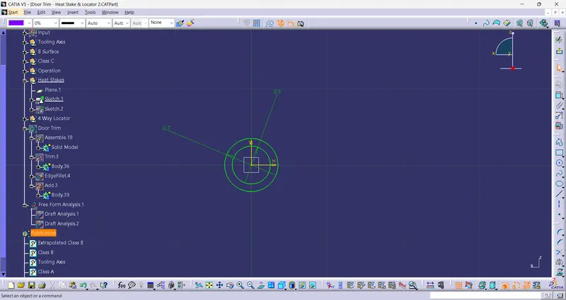
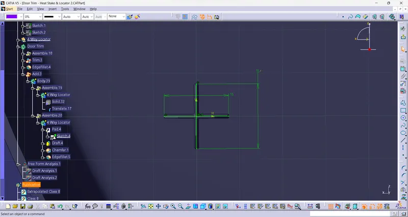
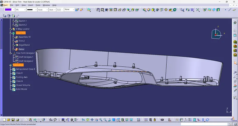
- A we have points to create heat stakes, so a ositioned sketch is drawn at oe of the point and Pad it for 20mm.
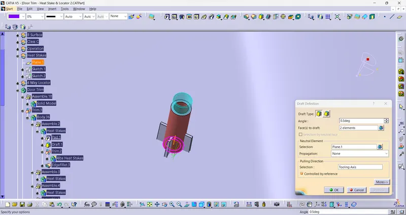
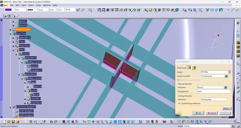
- A draft of 0.5 degree is provide to the walls of heat stakes in tooling direction.
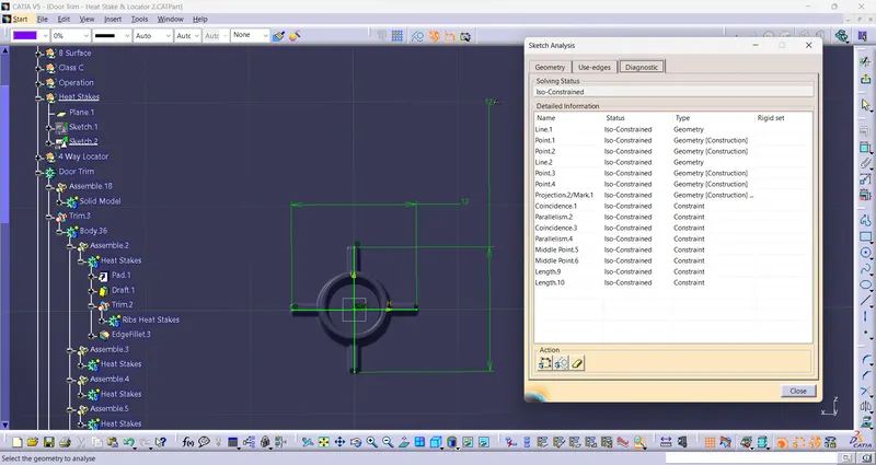
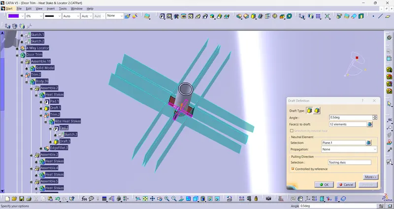
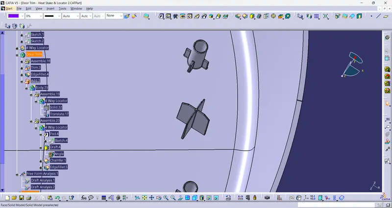
- To provide support to the heat stakes, ribs are created and trimed with the heat stakes bode. Ribs are also drafted for 0.5 degree.
- Now to create the heat stakes and remaining points, translate command with point to point translate is used.
- For locators, created two points on ehe surfaces, and drawn a sketch. Pad the sketch for required length and provie draft to the faces.
- The length of the locator should be more than the Heat stakes, as while assembling locators neeed to be inserted first.
Heat Stakes Screenshots: