Week 10 - Challenge 3 - Door Trim Lower with Engineering Features
Objective: The main aim of this challenge is to create a solid body of 'Door Trim Lower' with the help of the closed surface method by using the 'Generative shape design' workbench in CATIA V5. Performing the 'Draft Analysis' on the solid part body of the Door trim.
Introduction:
Locators: Locators are used in the manufacturing and assembly of automotive plastic products to ensure that components are aligned precisely and consistently. In this project, we have made 4-way locators.
Heat Stake: Heat staking is a process that joins two or more materials together using heat and pressure, and is used in automotive plastic products to:
Join parts- Heat staking is used to join plastic parts to metal parts, or to join two different plastic parts. For example, heat staking is used to assemble car door panels and to connect infotainment display components and dashboard accessories.
Create a permanent assembly- Heat staking creates a permanent assembly without the need for fasteners or hardware.
Minimize vibration- Heat staking uses precise thermal control and motion to minimize vibration.
Complete design process:
I received the class-A surface as our input to create a think-part body in which we can attach B-side engineering features like locators and heat stakes.
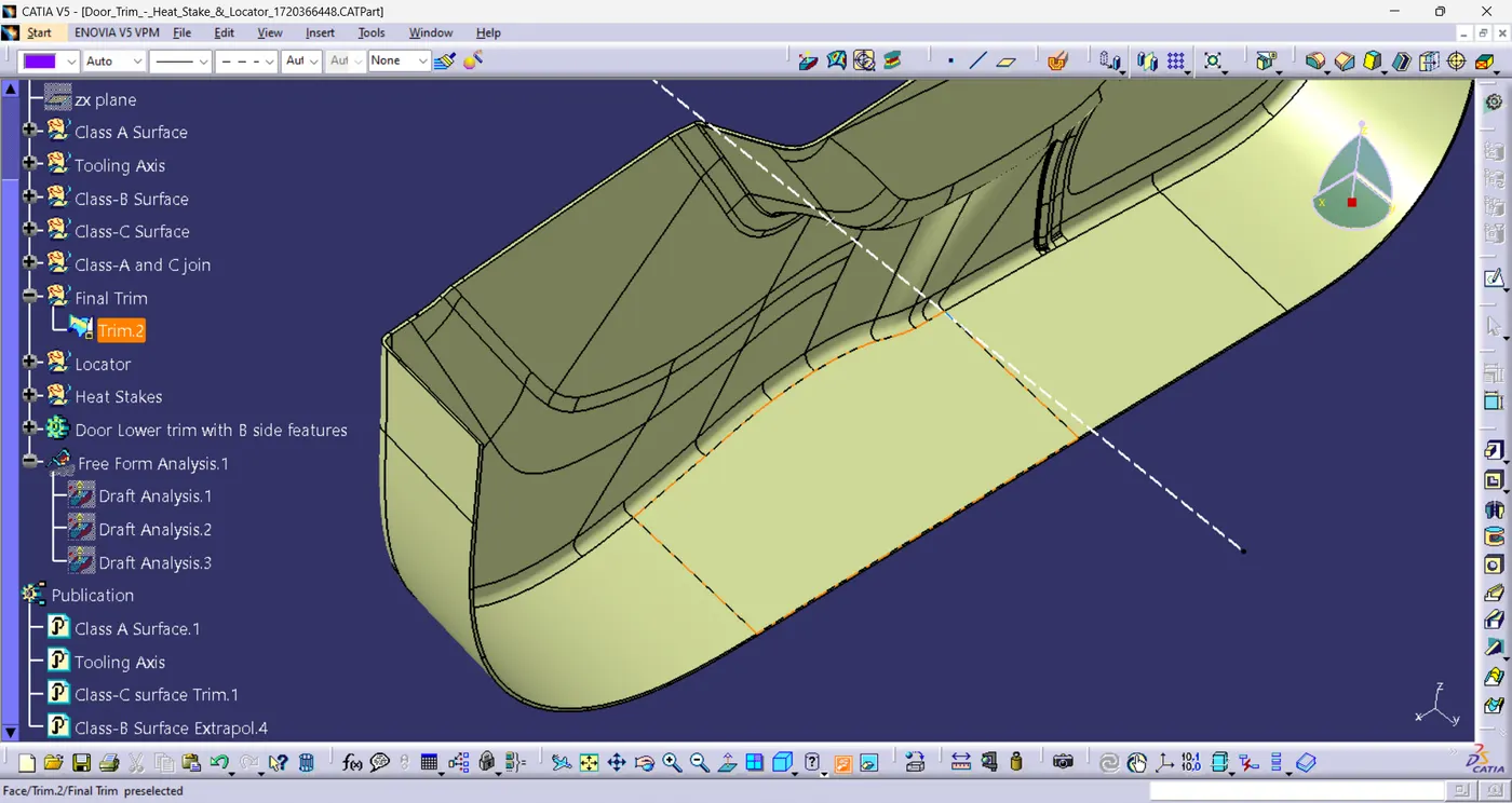
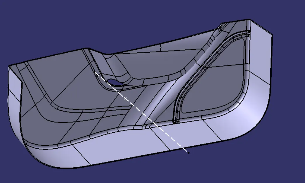
The very 1st thing I will do is to create a tooling axis so that the part can be cleared during the draft analysis. Then I'll create class-B and C surfaces using Offset, Boundry, Extract, Multi-Section surface and sweep command in Catia V5 software. After creating a closed surface using Class-A, B, and C surfaces I will create a solid part body using close body command in part workbench. All the pictures are shown below for creating a solid part-
Tooling Axis along with Class A surface-
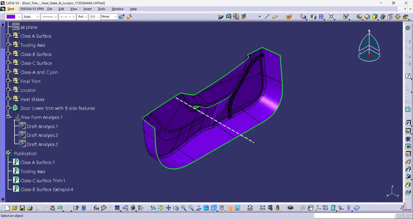
Draft Analysis of Class A surface-
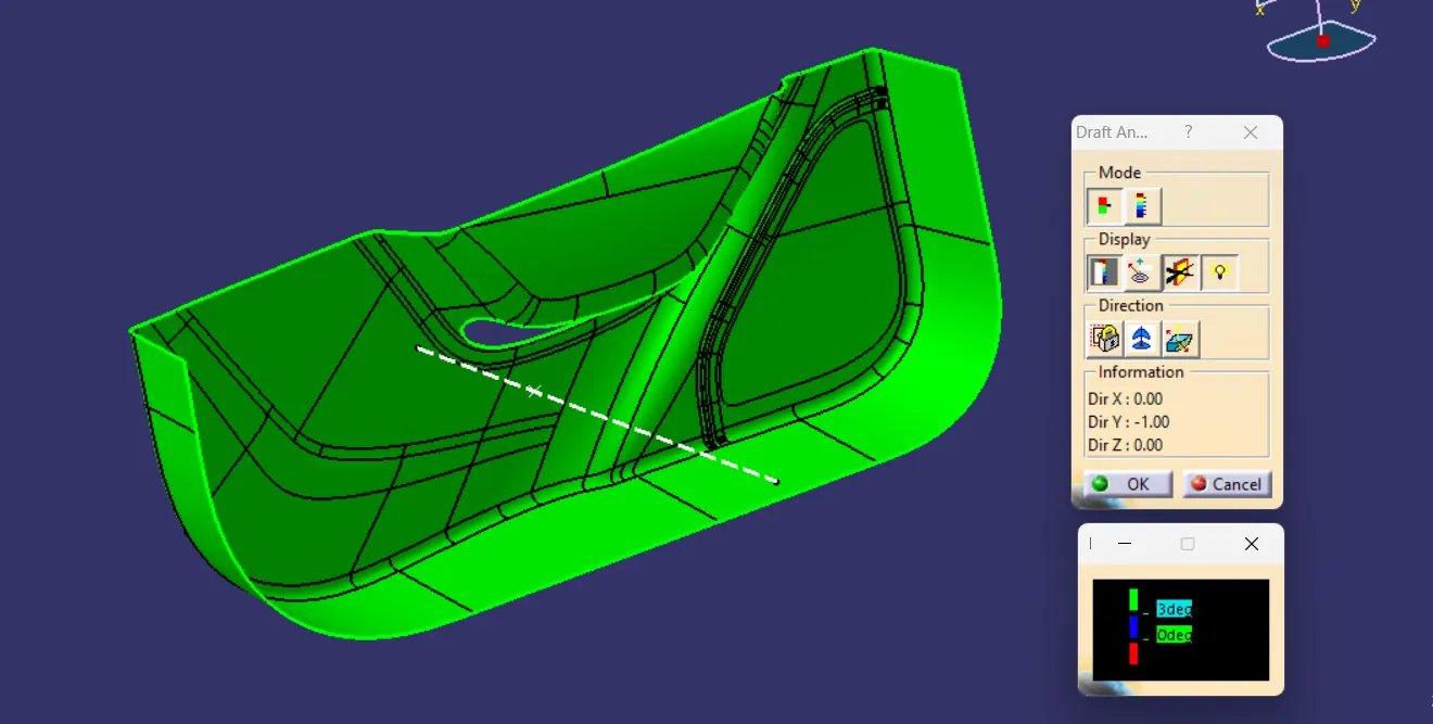
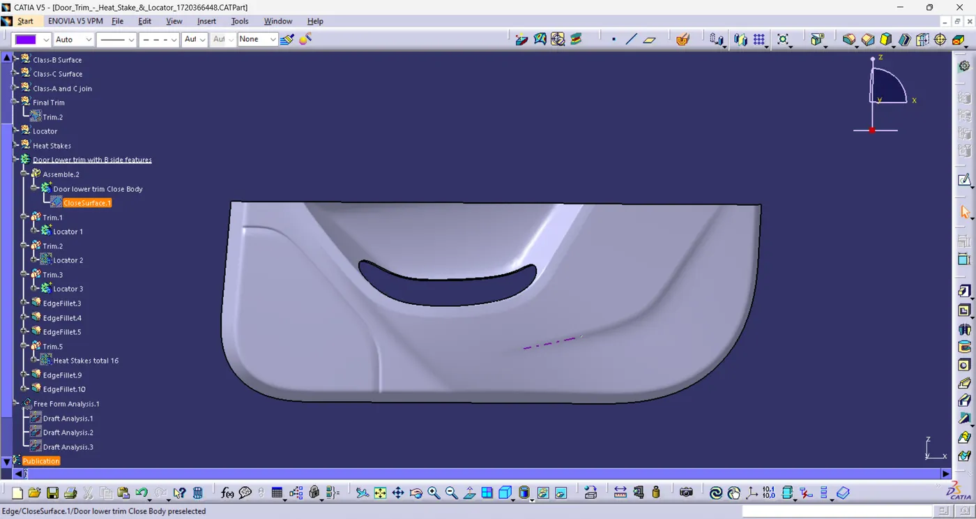
Final Close Surface created using Class A , B and C surfaces-
Solid Part Body-
Locator creation and Postioning-
After creating the solid body I created a positioned sketch for 4 way locator uning point, plane and line command as shown-
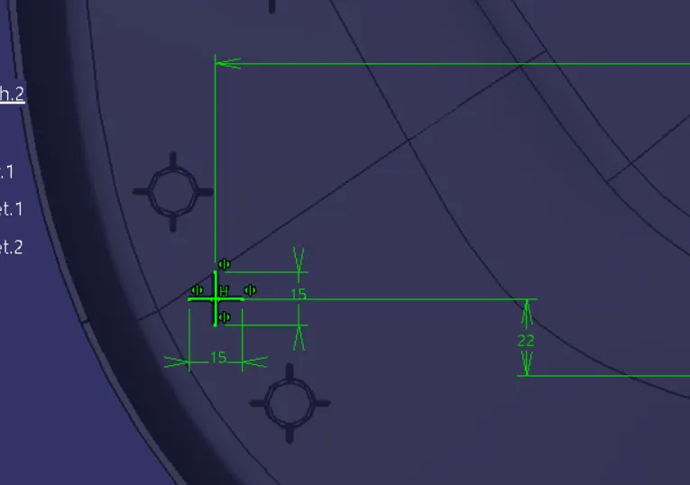
Then paded the 4-way locator using thick option because lines cannot be padded without using thick option as lines are not a close profile. The rules which are used to create a rib the same rules where used to create the locator as well. Important point while designing locator is the height of the locators must be higher than the heat stakes and are at equal length from the bottom surface to tip of the locator. After creating 1 rim I copy pasted the same locator body twice to create 2 more locators and positioned them on the lower door trim accordingly as shown-
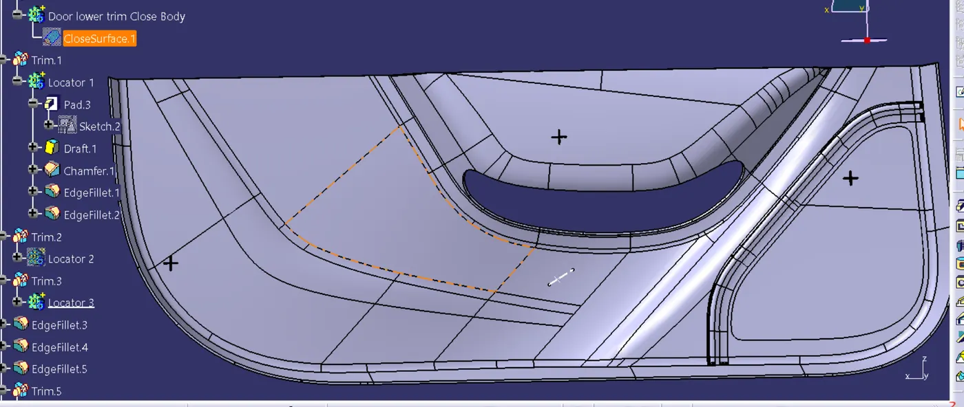
Heat Stake Design and positioning-
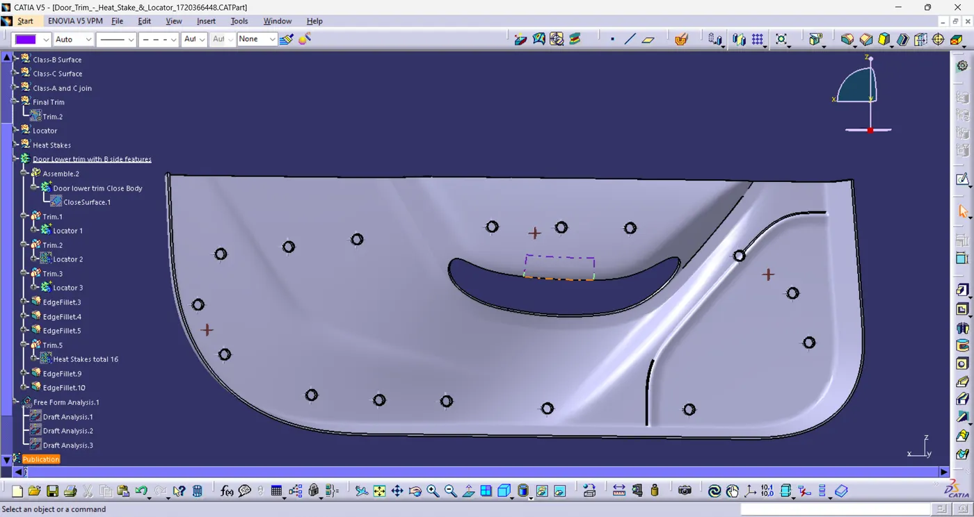
After Locators the next thing to design is heat stake, For heat stakes positions multiple points where create on the door trim at a specific distance and to make sure that no points should over lap any other engineering features. After defining points I created a heat stake sketch and padded it, copy pasted it and then did a point to point translation all pictures are shown below-
Heat stake Sketch-
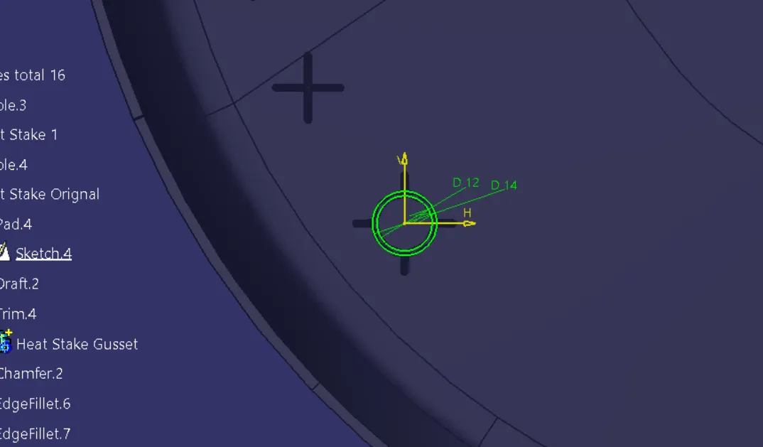
Heat Body along with positioning-
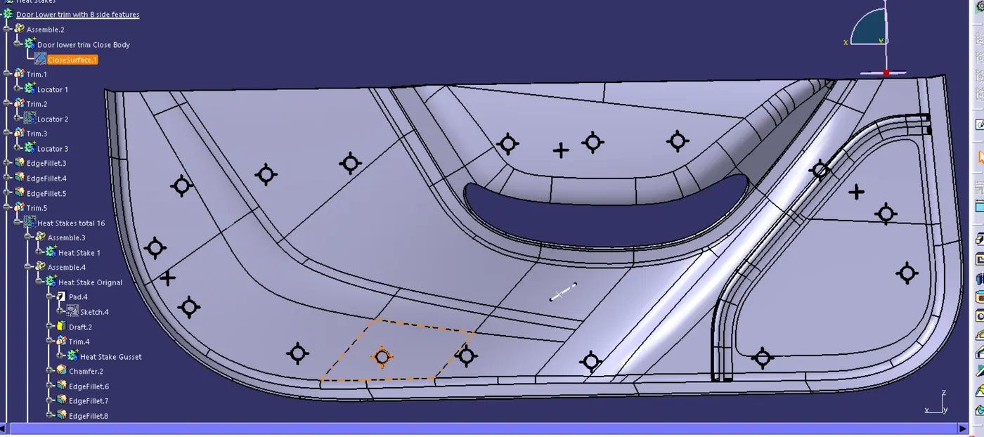
I also provided minimum draft required to create the locators, Heat stakes and Lower Door trim manufacturable for locators and heat stakes draft value is 0.5 degree and for door trim draft value is 3 degrees.
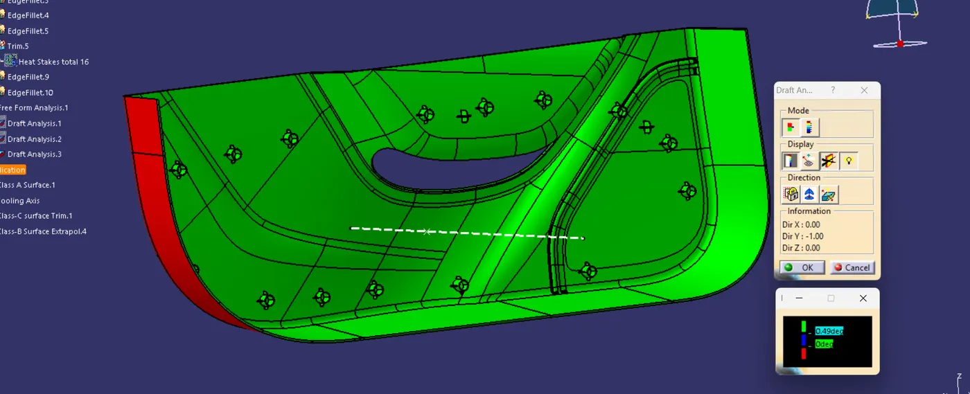
Used boolean operation (Union trim) to assemble locators and Heat skates to the door trim. Did final draft analysis of the final part as shown-
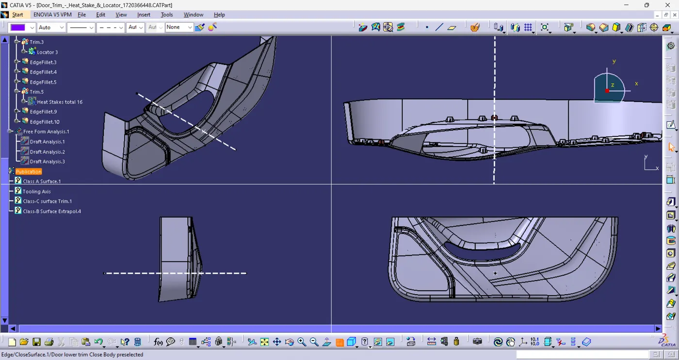
Screenshots of the completed design in various orientations (Isometric, Front, Side, and Top View)-
Thank You.