Week 10 - Challenge 3 - Door Trim Lower with Engineering Features
Week 10 - Challenge 3 - Door Trim Lower with Engineering Features
Aim:
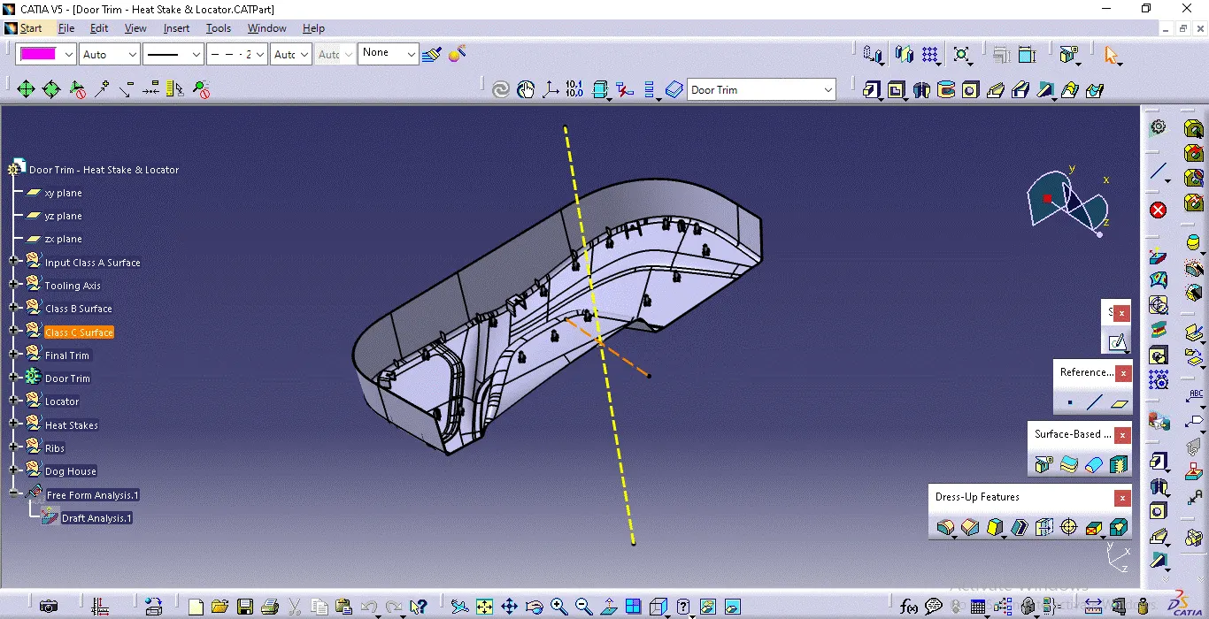
Creation of proper tooling axis considering the required draft angle of a component Performing draft analysis on the given Class A Surface and Creation of Class B and Class C Surface Adding the Heat stake and locators to the Door Applique trims.
Tooling axis:
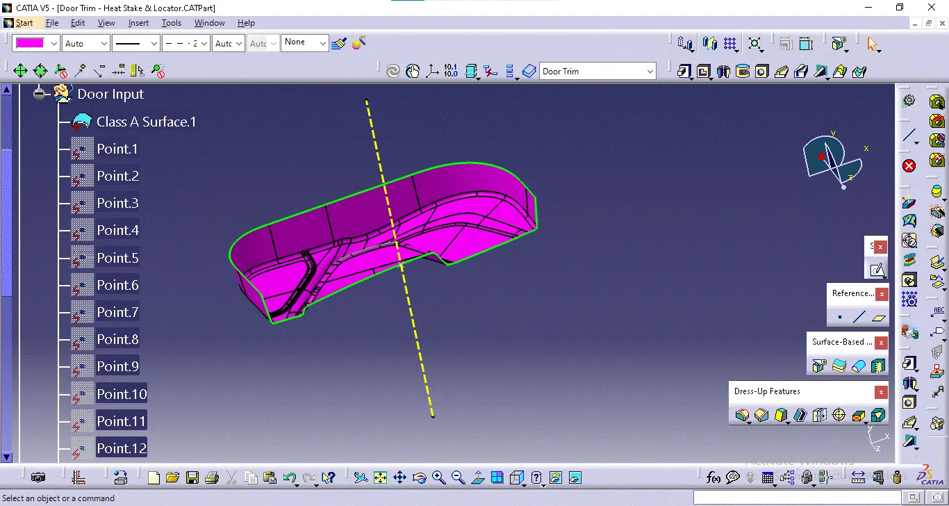
To create the tooling axis, first determine the direction using the Class A surface. In the direction, identify the surface patches, create a midpoint on the curve, and insert a line using the [point direction] line type. Verify the correctness of the line with a draft analysis by fixing the compass on the line and ensuring the draft analysis is clear. To create the tooling axis using the Class A surface, view the surface along the Y-axis to see all patches clearly. Place a point at the midpoint of a key curve, then insert a line using the "Point-Direction" type along the Y-axis. This line will serve as your tooling axis.
Draft Analysis
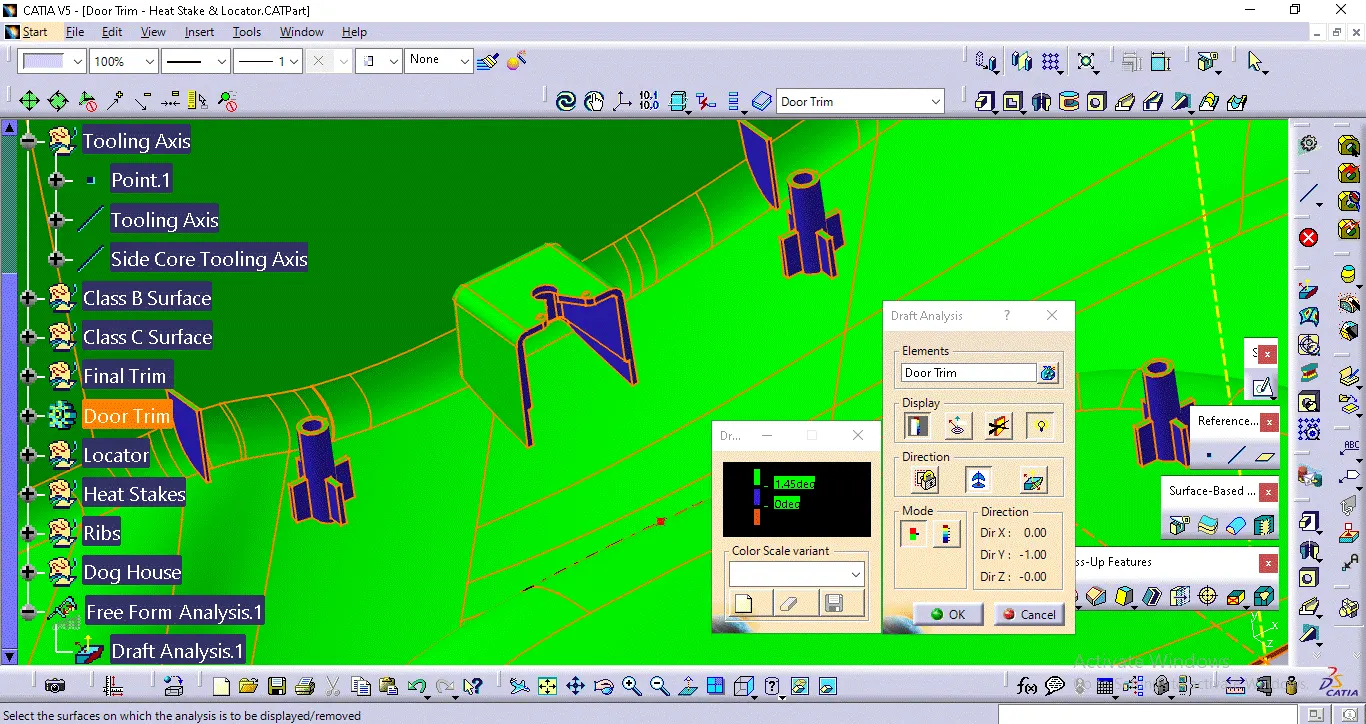
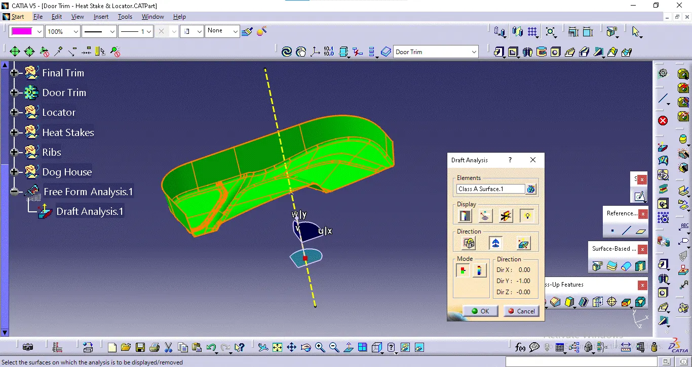
To perform draft analysis, click Insert > Analysis > Feature Draft Analysis. Open the Draft Analysis toolbar, go to the display block, and select Analysis under the Running Point to check angles on the Class A surface. The color scale indicates if the draft angle meets the 3-degree requirement using colors green, blue, and red. After analysis, align and fix the compass to the tooling axis by selecting Use the Compass to Define the New Current Draft Direction in the Direction block, aligning the compass with the tooling axis, and clicking the lock symbol. Finally, click OK on the Draft Analysis toolbar to complete the process.
Creating Class B Surface:
To create a Class B surface from Class A surfaces, first extract the Class A surfaces and untrim them to their full extent. Ensure proper intersections by using extrapolation as needed, then trim and offset the surfaces by 2.5 mm to achieve the desired thickness. Place the trimmed surfaces into a new geometrical set and name it accordingly. Apply fillets to the edges, adjusting the component thickness if necessary to maintain uniformity. Finally, review and refine the geometry to ensure all surfaces meet design specifications and requirements.
Creating Class C Surface:
To generate the Class C surface, start by using the Class A and Class B surfaces as references, where the Class C surface will define the thickness between them. In the Surface Workbench, utilize the Sweep command to create the Class C surface. Select the boundary of the Class A surface as the profile and align the sweep along the tooling axis, setting a draft angle of 3 degrees. This draft angle should be applied to the sweep, and if necessary, use it to create any holes required by the design. Once the Class C surface is swept, join it with the Class A surface to ensure a continuous and smooth connection. Following this, trim the Class B surface with the Class C surface to refine the overall geometry of the part. Finally, use the boundary command to check and confirm the alignment and precision of the surfaces, ensuring that the Class C surface is well-integrated and meets quality standards.
Engineering Features
Heat staking
Heat staking is a precise process used to join materials, especially plastic to metal or plastic to plastic, by deforming the plastic with heat and force. Key design considerations include the stake's shape and size, which impact material flow and joint strength; the compatibility of the materials being joined, particularly their thermal properties; and the need for custom tooling to ensure even heat distribution and consistent force application. Process parameters like heat, force, and time must be carefully controlled to avoid defects, and post-staking inspection is essential to ensure a reliable bond. Strategic stake placement also helps distribute load evenly and prevent stress concentration.
Locators
Locators are essential supporting features in plastic design, used to position and stabilize components by restricting movement. A minimum of two locators are required, with 4-way and 2-way locators being common options. A 4-way locator, typically formed by the junction of four ribs, restricts four degrees of freedom, ensuring precise alignment. It's crucial that the height of locators is greater than that of heat stakes to provide effective support and stability during assembly.
Dog house
A dog house is an attachment feature used to position components at precise heights and fix plastic defects during assembly. You should use the specific design provided in your resources and follow the master section or engineering drawing closely to ensure accurate placement and effective resolution of issues.