Week 10 - Challenge 3 - Door Trim Lower with Engineering Features
Aim:
To create the door trim lower part using the specified class. Using CATIA V5 software, create the engineering features (heat stakes and locators) on the component's surface.
Objectives:
The tooling axis is created with the proper draught angle. forming additional surfaces (such as B and C surfaces) in order to form a solid component. Conduct preliminary analysis on the Class A surface and the resulting solid model.
Procedure followed:
· Tooling axis creation
· Draft analysis of class A surface
· Class B surface generation
· class C surface generation
· Final trim
· Solid body generation
· Draft analysis of the solid body
· Locator creation
· Heat stakes creation
· Translation
· Draft analysis of the B side features
Tooling axis creation:
Orient the class a surface in several viewpoints, then select the optimal view to produce the part all at once. Next, separate the surface from the class A surface, mark the middle of the extracted surface, and draw a line in the direction of view. Then designate it with a tooling axis.
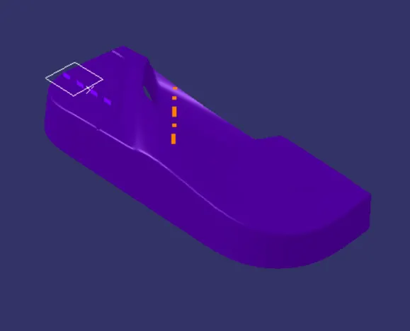
Class A surface:
Class a surface is an aesthetic surface with a polished surface which will be visible for the customers, and with the aid of the class A we could be able to generate the class B and class C surfaces
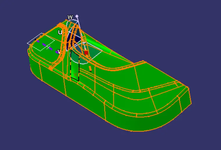
CLASS A SURFACE DRAFT ANALYSIS:
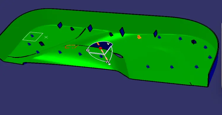
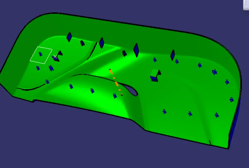
Prior to creating the solid and B-side features, we do the class A surface draught analysis check. I then set the compass to line up with the tooling axis, and I assigned the green hue in the colour bar a 3-degree draft angle. When a surface is indicated in green, the draft angle for a class A surface is appropriately determined. One possible explanation for the class A surface's draught angle is that it is not fully highlighted in the hue green.
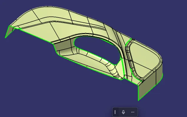
Class B surface:
class B is an engineering surface where the B side features include the ribs, screw bosses, doghouses are located.
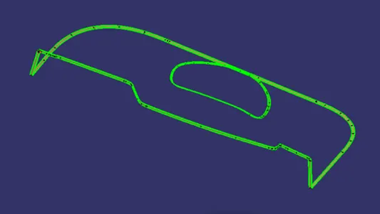
Class C surface:
Class c is an intermediate surface between the class A and class B surfaces. It is generated by sweep feature either with reference surface or with the draft direction. If the generated C surface is parallel to the tooling axis, then we make the aid of the draft direction or else proceed with the reference surface.
Creation of B side features:
CREATION OF LOCATORS:
To create the locators, I created a sketch on the body. After creating the sketch, I pad it 22mm in height and thicken it to 1.3mm and I drafted it with 0.5deg in the direction of the tooling axis. I gave 5mm of chamfer with 45deg of inclination and after I gave a fillet of 0.25mm radius.
4-way locator:
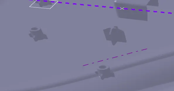
HEAT STAKE CREATION:
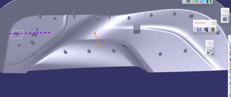
Following the development of the sketch, I padded it to a height of 16 mm, added a fillet with a radius of 0.25 mm, and gave both the interior and outer sides a 0.5-degree draft angle.
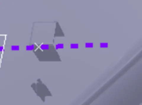
DOG HOUSE CREATION:
DRAFT ANALYIS:
Conclusion:
Therefore, using the class A surface that is provided and the standard design parameters for the B side features, the door trim lower with the engineering features—including the heat stakes and locators—is designed using the catia v5 software, and the cat component is submitted in the browse option.