Week 10 - Challenge 3 - Door Trim Lower with Engineering Features
AIM
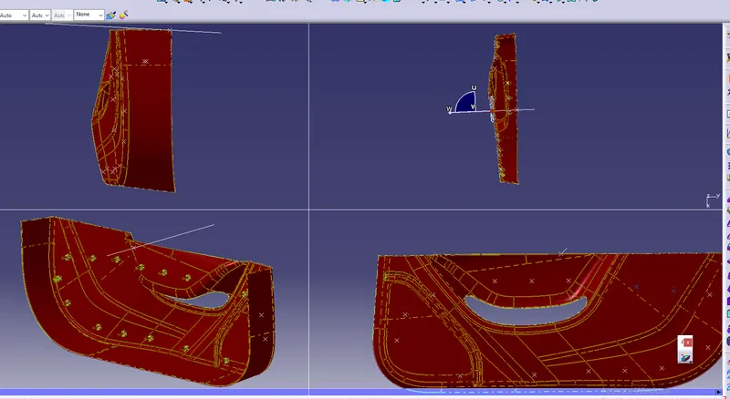
Create the Door Trim Lower Plastic component through the given Class-A surface. To begin with, the tooling axis for the given Class-A Surface should be created meeting the requirements of the draft angle and at the end perform the Draft analysis on the model.
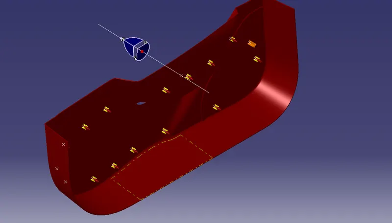
Report of draft analysis
In a draft analysis we have to position the tool direction on surface class A and the compass should be lock in the tool direction and then check the analysis under running point should check the draft angel on the surface oh the class c
If the
red represent - no draft
Green represent - positive draft on cavity side
Blue represent - negative draft on core side
Please check the report in given below attached file for draft analysis
CLASS A SURFACE DRAFT ANALYSIS
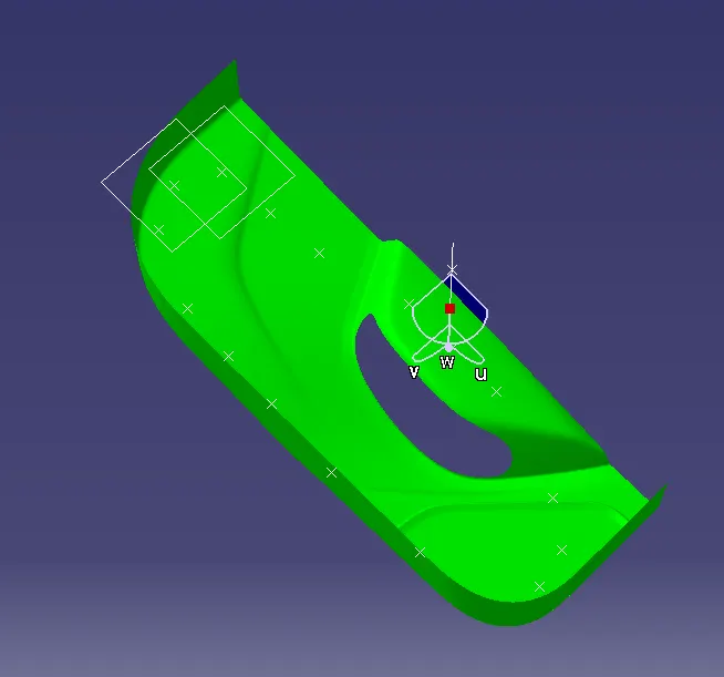
CLOSED SURFACE DRAFT ANALYSIS
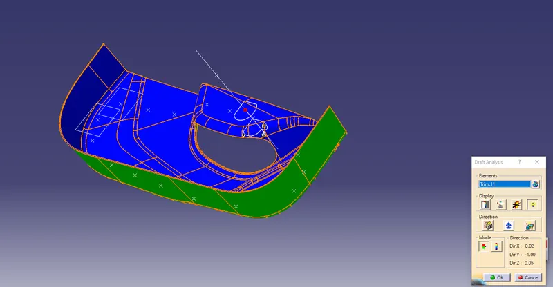
ENGINEERING FEATURES DRAT ANALYSIS
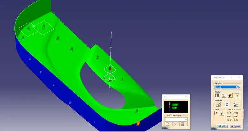
Surface A
Repair the class a surface there is a n number of surface we should be the join the all surface together in single surface
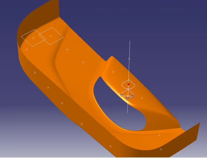
Tooling direction
We make a point & line in on the surface on the hole center for tooling direction
And the tooling direction depends upon the surface of draft angel given by as and then we move on the tooling direction
And the direction of compass should be an lock through the line along the surface
If the tooling direction to desired the cavity and core side of the surface
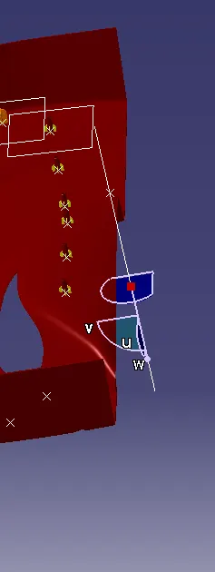
Surface b operation
1st we start form the surface a and then offset 2.5mm from the class a toward the an z direction
- Crean ate offset surface of Cin CLASS-A about 2.5mm inward direction.
- Check for discontinuity and rework on the offset surface using extract, multi-extract, multi sections surfaces.
- Join the surfaces and ensure the final CLASS-B surface created has no gaps.
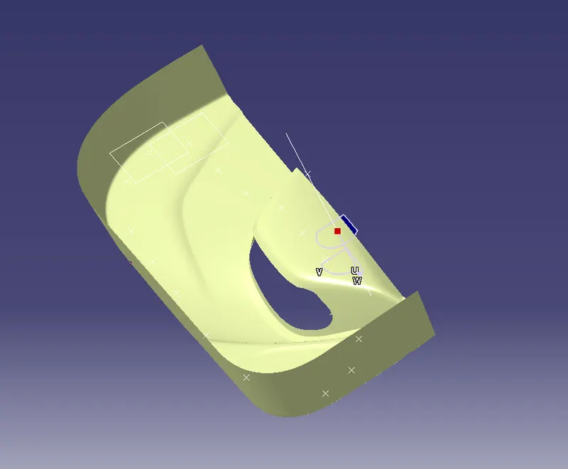
SURFACE C
The surface that joins class-A and class-B surfaarethe s is class-C surface. Class C is often specified for interior surfaces not readily visible, surfaces that will be covered by another part when assembled
- Create the sweep concerningerence to the surface and tooling axismulti-extractingting the CLASS-A boundary
- Join the sweep surfaces by using commands like extrapolate, trmulti-sectiontion surface.
- Finally join all the sweep surfaces and ensure the continuity of the CLASS-C surface.
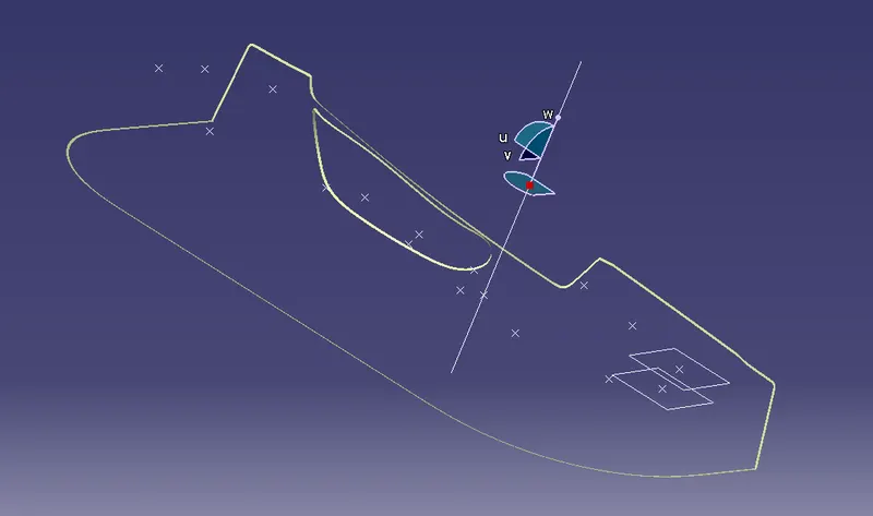
TRIM operation
- For creating the Finals door trim surface, join the CLASS-A and CLASS-C surfaces together.
- Then Extrapolate the B surfacea little bit outward direction to make sure that there would not be any gap when trimming with the joined surface.
- Then trim the extrapolated CLASS-B surface wthe ith Join surface (CLASS-A and CLASS-C)
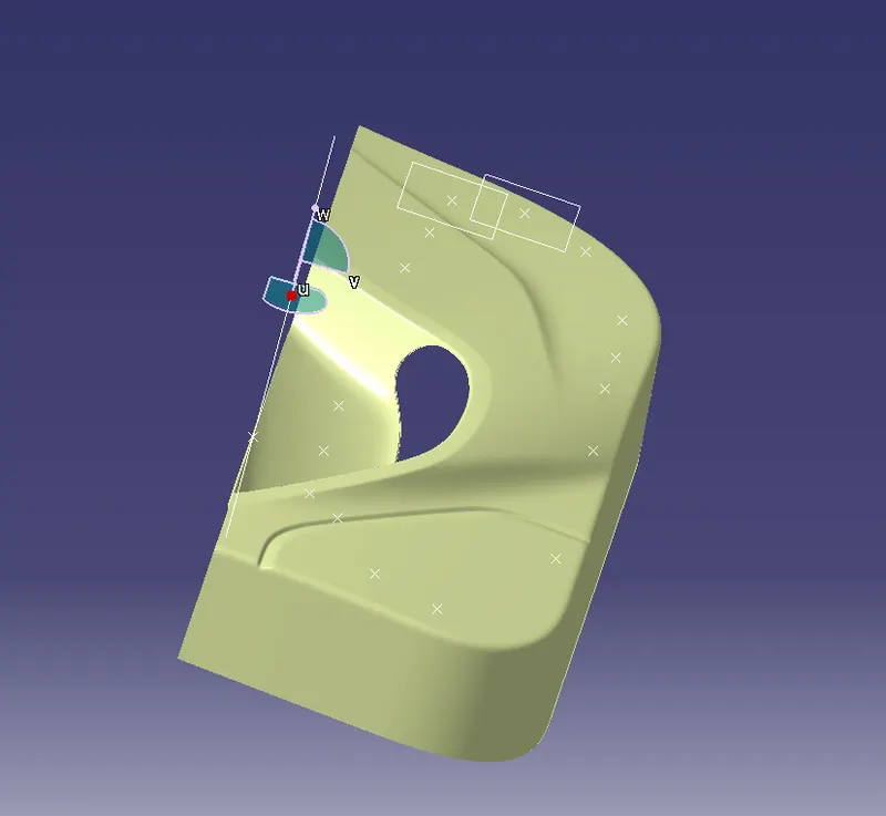
CLOSED SURFACE
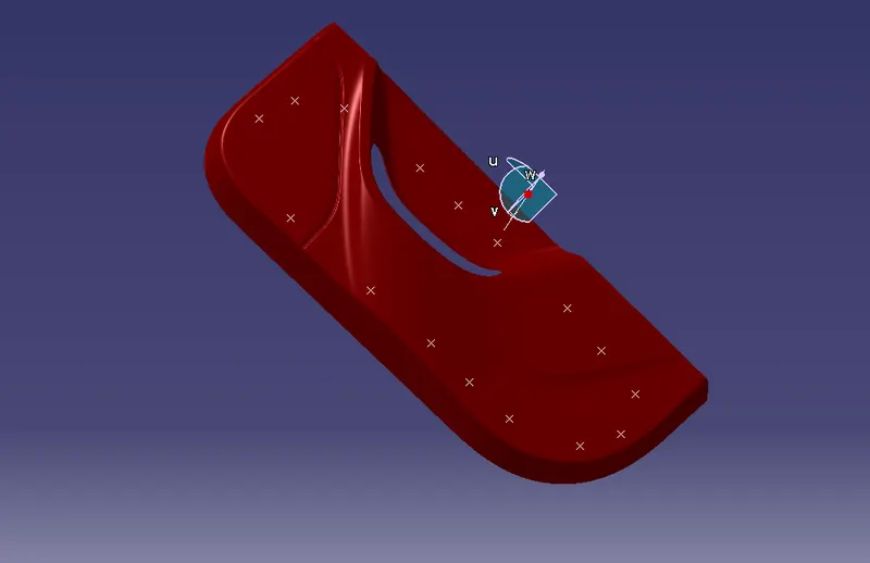
B SIDE FEATURE CREATION
HEAT STACK CREATION
- First, create a reference plane on the B surface and draw the profile for heat stack.
- Use Pad option on part design to the sktech and pad it ti the height of about 20 mm.
- Now, use draft on the padded surface with an draft angle of about 0.5 degree.
- Then, draw a cross section lines of about 15 mm each for making the ribs for heat stack.
- Again use Pad to the sketch and use draft on it.
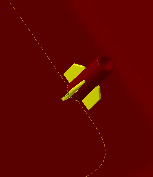
FOUR WAY LOCATOR
- Create a cross secting line of about 15 mmm each and symmetry it to the axis.
- Use Pad to the sketch of height 20 mm. And use draft on it with an angle of about 0.5 degree.
Finally, add all the engineering features to the solid component and use draft analysis to the final component.
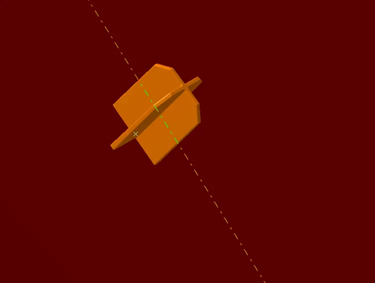
design in various orientations (Isometric, Front, Side, and Top View)