Week 10 - Challenge 3 - Door Trim Lower with Engineering Features
AIM : To Create the Door Trim Lower Plastic component through the given Class-A surface and to Create the Heat Stakes and the locators considering the design rules mentioned for the door applique.
Creation of proper tooling axis considering the required draft angle of a component
It is defined as the direction in which the mould/core and cavity open. Selection of the direction of the tooling axis depends on the ease at which components can be easily ejected.
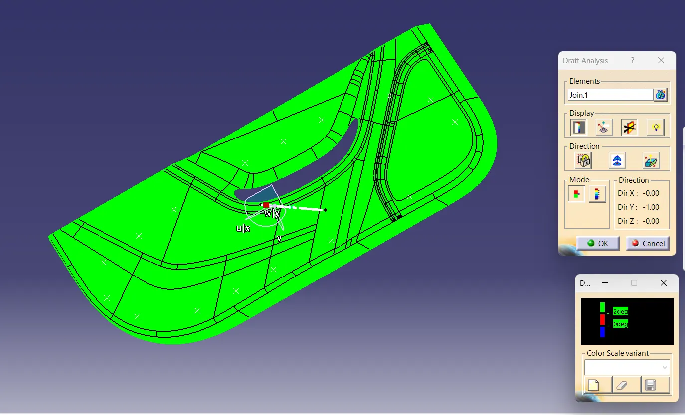
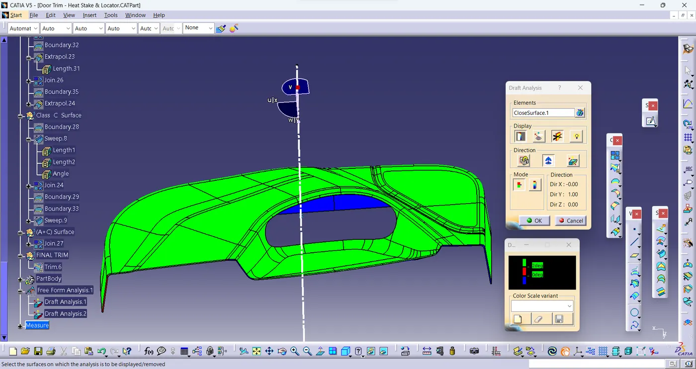
First, we'll view the Class A surface from all three axes to determine the most suitable direction along which the Main Tooling Axis can be created .
a) VIEW ALONG THE Z-AXIS:
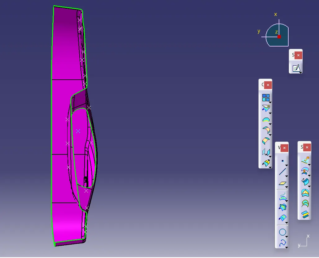
b) VIEW ALONG THE X-AXIS:
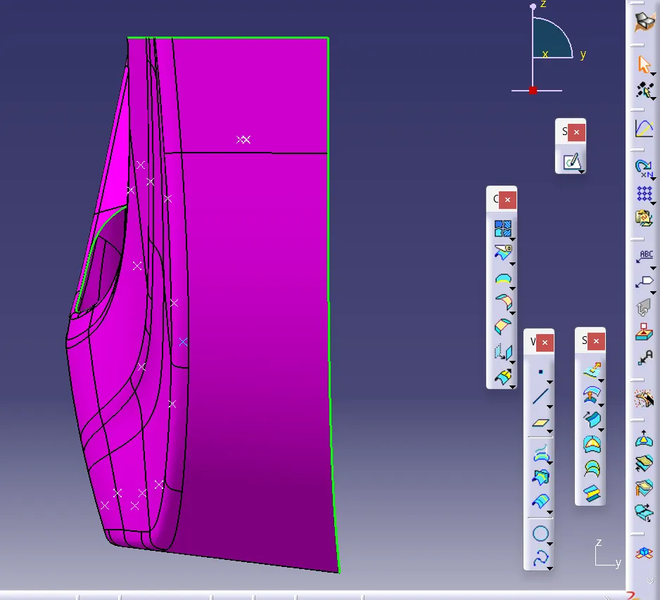
From the above image, we can notice that the case here is also similar to the view from the Z-axis as not much area is exposed here and even the hole section is not entirely visible from this direction. Therefore, we cannot consider both these axes as our Main Tooling Axis as well.
c) VIEW ALONG THE Y-AXIS:
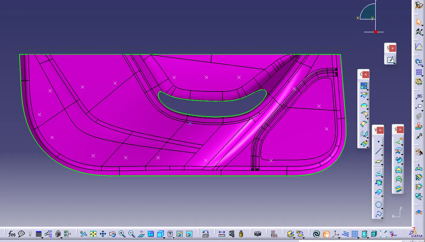
From the above image, we can observe that here the maximum amount of the Door Trim Lower's surface area is exposed and we can even view the hole section from this axis hence considering this direction as the direction of our Main Tooling Axis would be the most suitable choice compared to other directions .
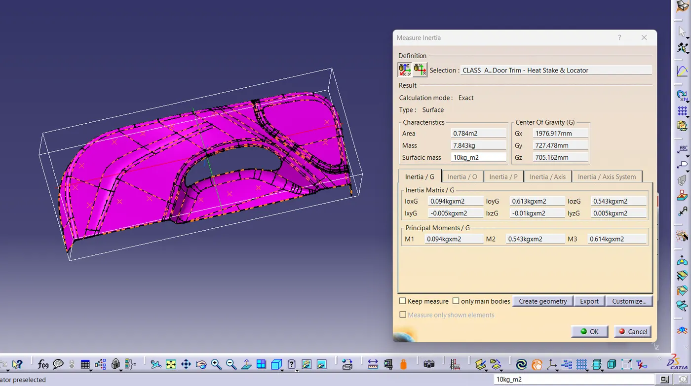
- In order to create Tooling Axis , First we need a point . So to create a point ,select "Measure Inertia " command and then select the Class A surface as shown
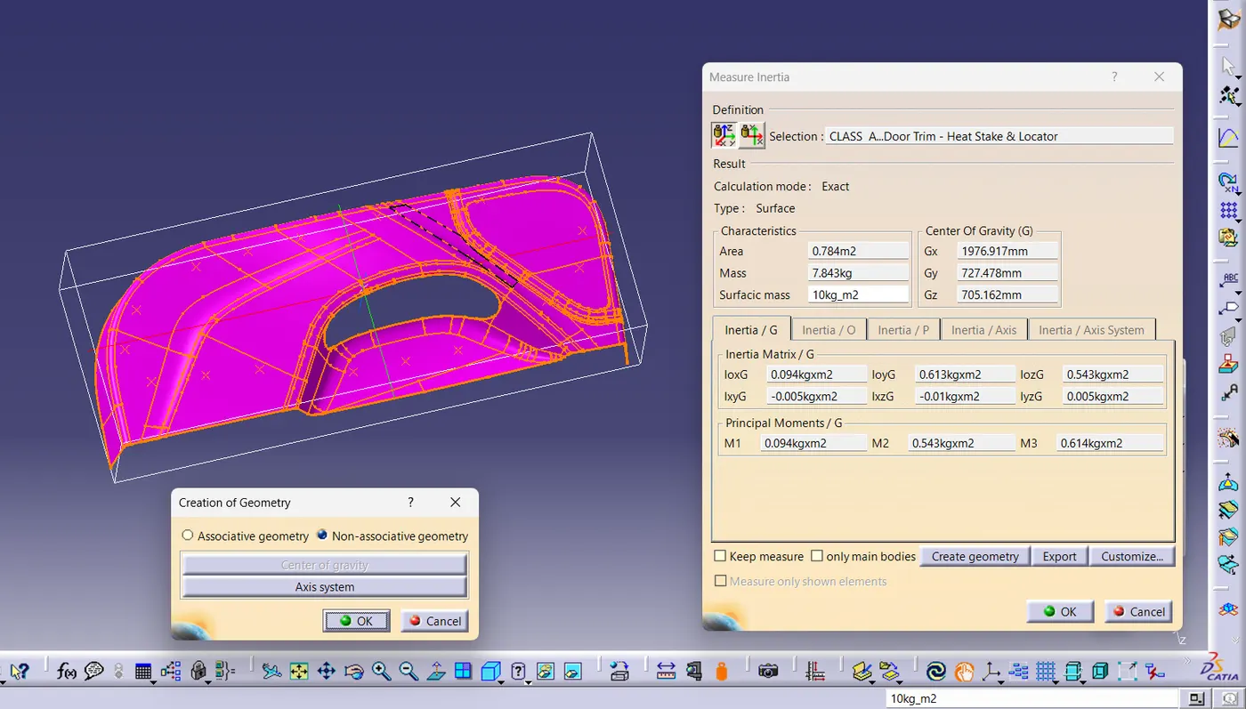
- Now select " Create Geometry " in the Measure Inertia dialogue box then a new window is opened up as shown . select " Non Associative geometry " and then click on " Centre of Gravity " to create a point.
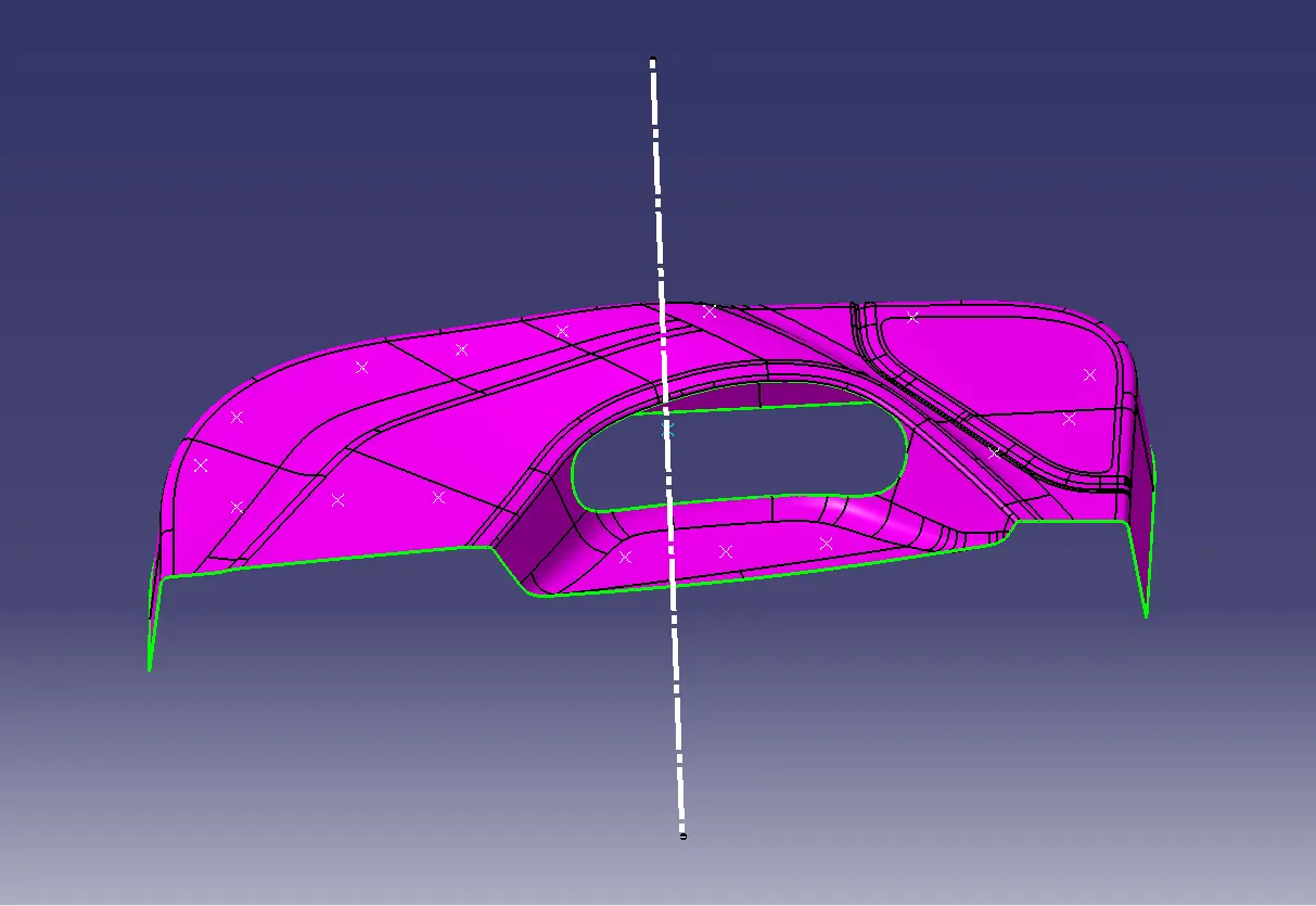
- Now create a Line using "Point - Direction " method ,select the point that is created using measure Inertia and Direction as Y direction .

- A detailed report should be done explaining the draft analysis
a)Class A surface
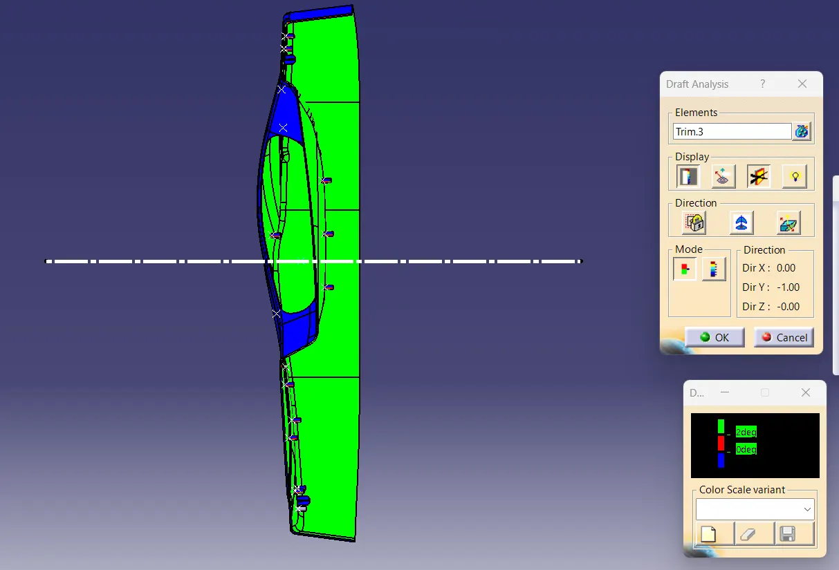
Before starting with a Draft Analysis Operation, we will go to the 'Customize View Parameters' option under the 'View Toolbar'. Then we will enter the 'Customize View Mode' where we will go under the 'Mesh' option and then select 'Material' and press 'OK' .
- Go to Insert-------> Analysis-------->Feature Draft Analysis . This will open the 'Draft Analysis' Dialogue box. There, we will ensure that under 'Mode' we have selected 'Quick Analysis'
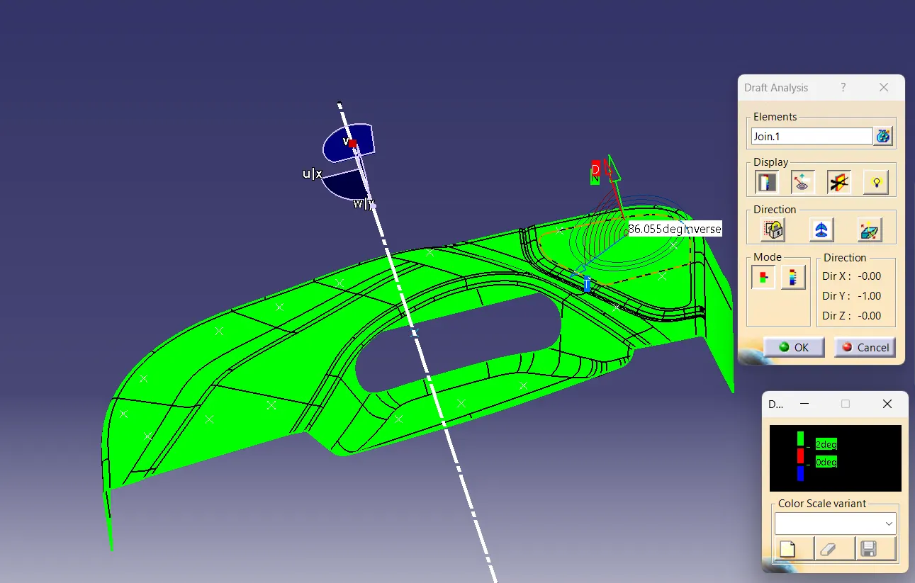
- Now click on class A surface and then drag the compass and place it on the Tooling Axis . Now activate the compass under 'Direction' and choose the icon with the symbol of the compass on it which stands for 'Use the Compass to define the new current draft direction'.
- Now again drag the compass out from the tooling axis and again place it over the Tooling Axis and then Select the class A surface .
- under 'Display' we will select 'Show or Hide the Color Scale' and then select '3 Degrees' as the permissible draft angle.
b)Draft Analysis on Final Component without Engineering Features
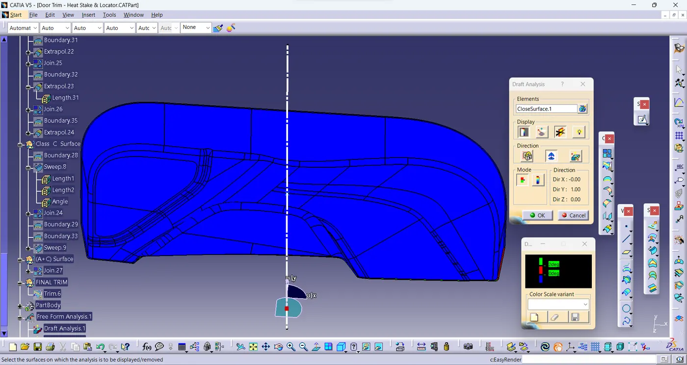
In the Draft-Analysis,
Green Colour stands for regions where the Draft Angle is more than 3 degrees,
Blue Colour stands for regions where the Draft Angle is between 0-3 degrees, &
Red Colour stands for regions where the Draft Angle is lower than 0 degrees
1)PROCEDURE TO CREATE LOCATORS
- We'll create the two points at which we are supposed to create the locators as shown
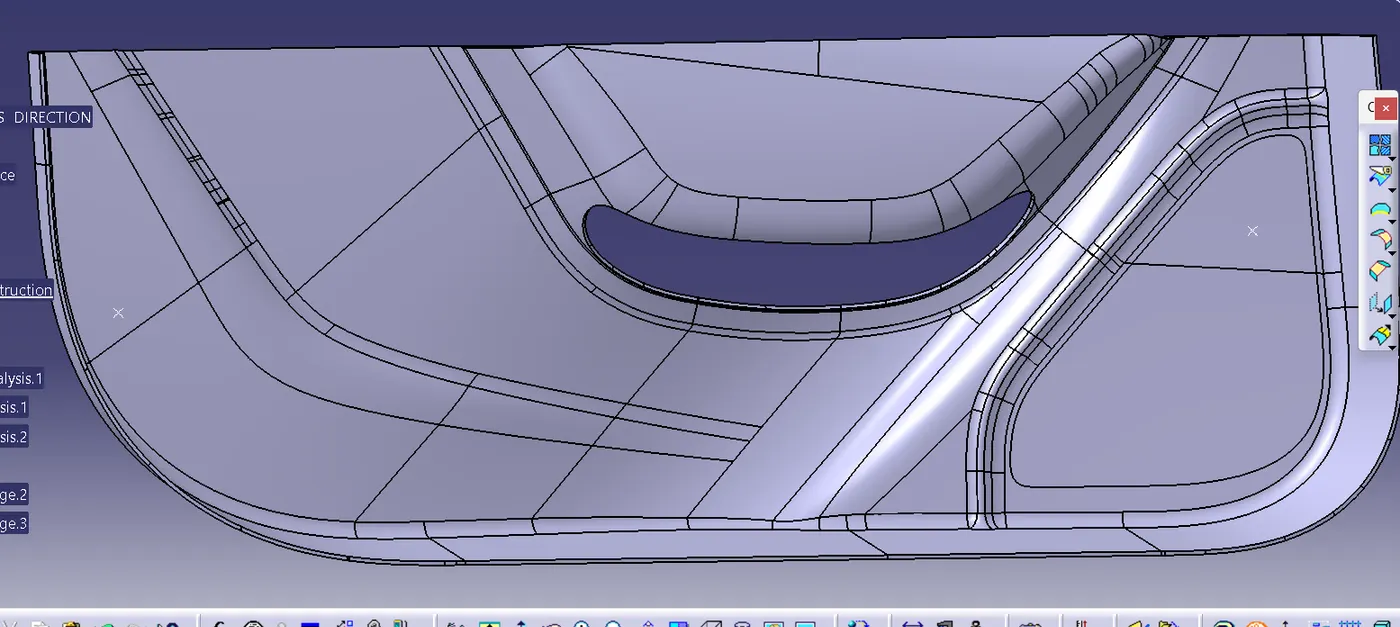
- Now We'll create the necessary planes using "Tangent to surface " and with point , so that we can create a positioned sketch with a projection point for the locator as shown below:
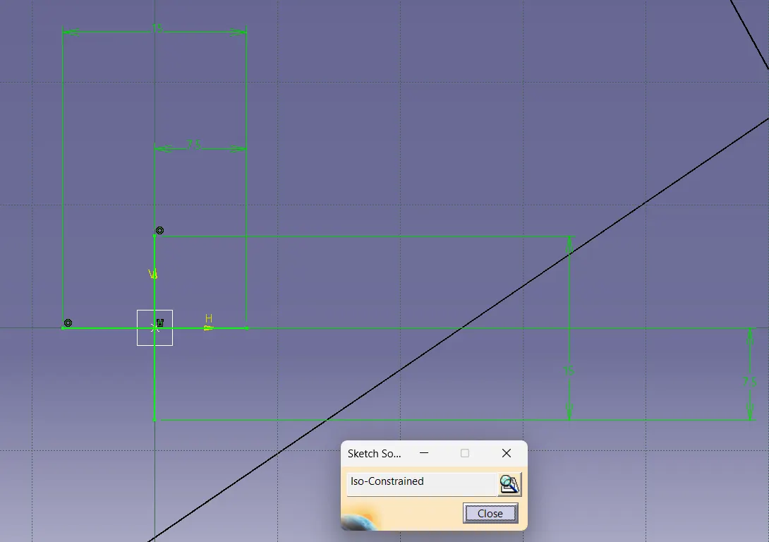
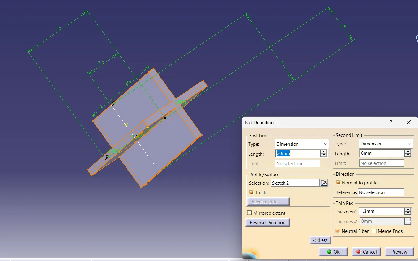
- Insert a body and Then, we'll go to the Part Workbench and use the PAD Command to create a Thickened Body with thickness as 1.3 approx with Neutral Fiber as shown below:
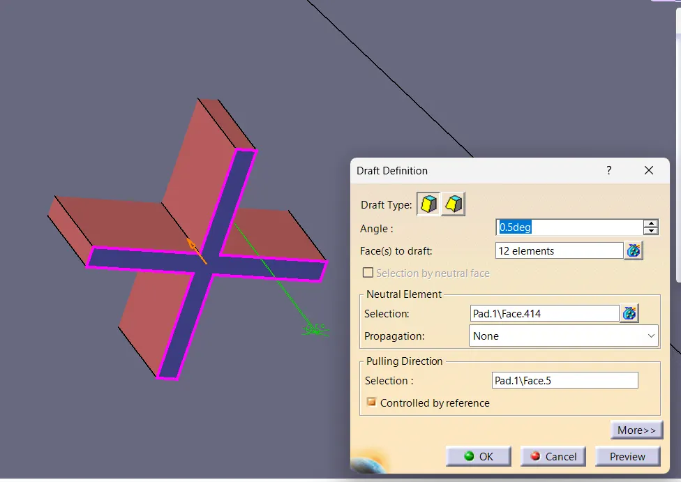
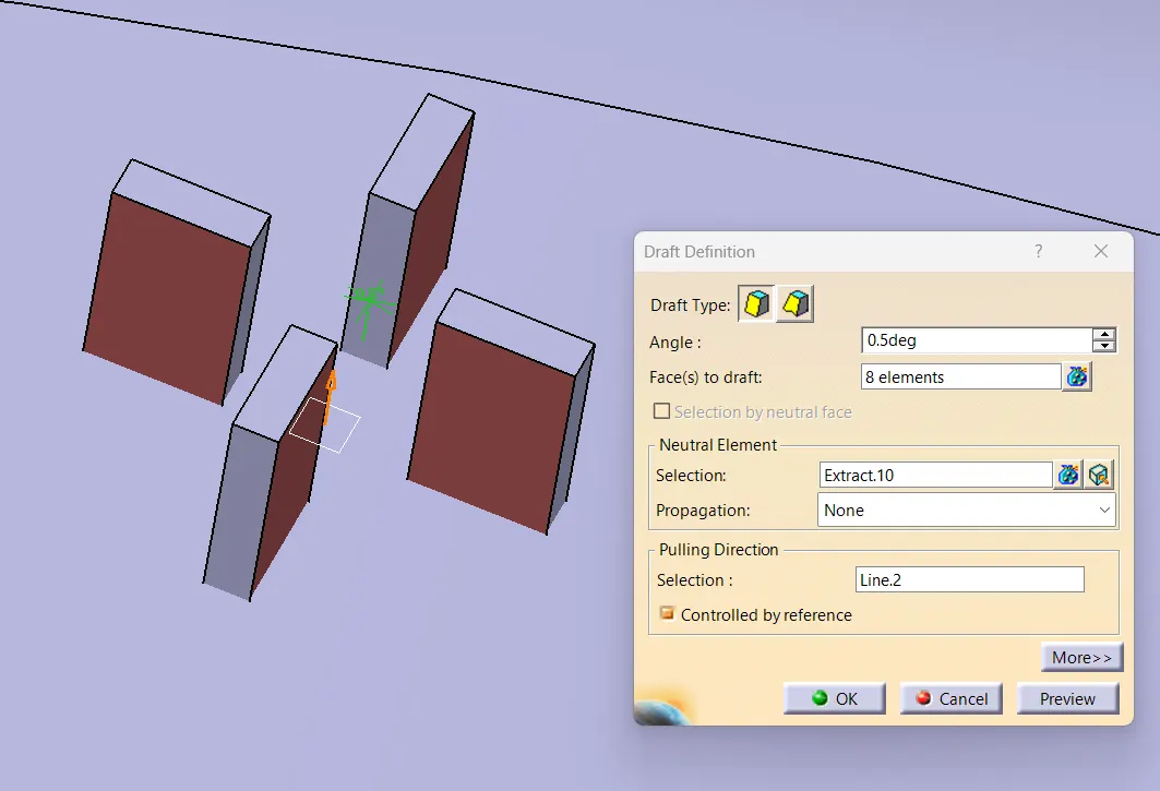
- Perform draft as shown
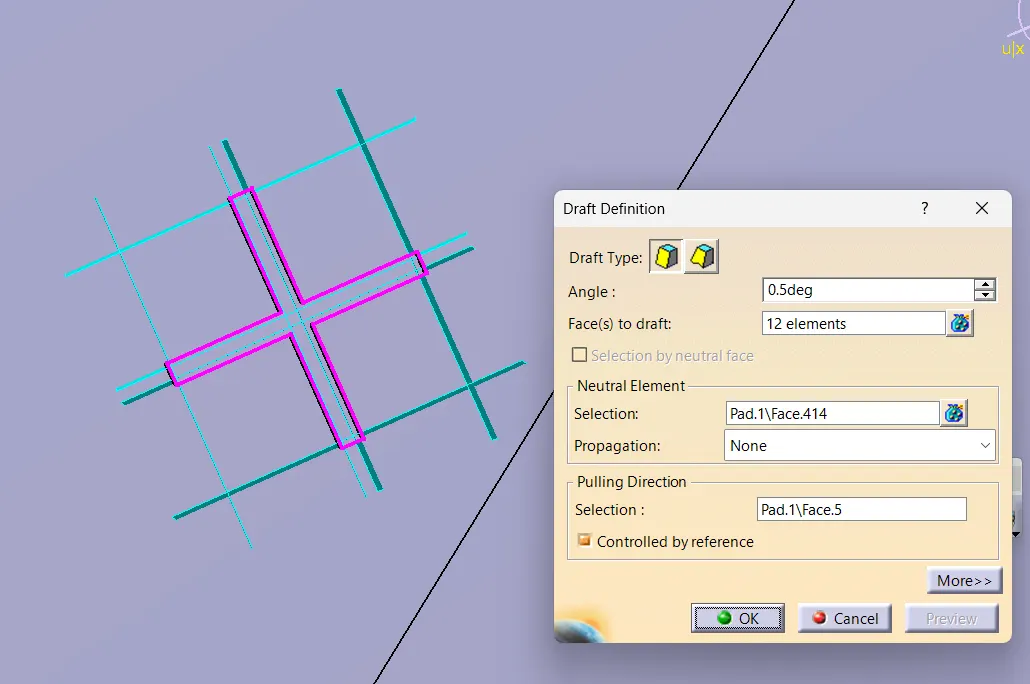
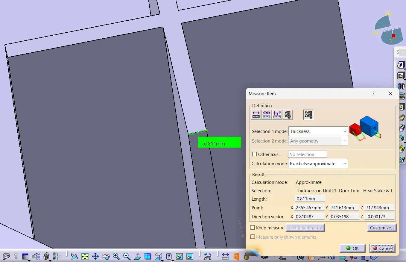
- After providing the draft we'll check the wall thickness at the top section as it should be greater than 0.75mm according to the design rules.
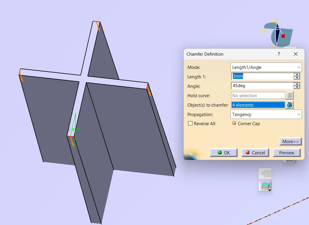
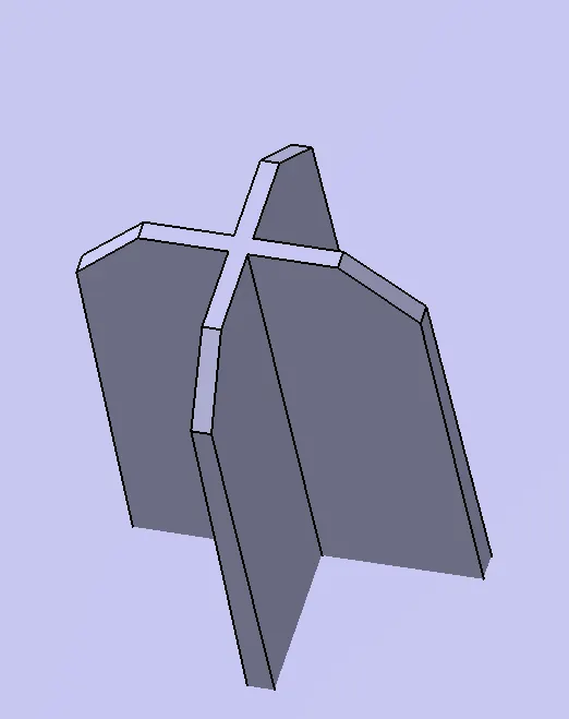
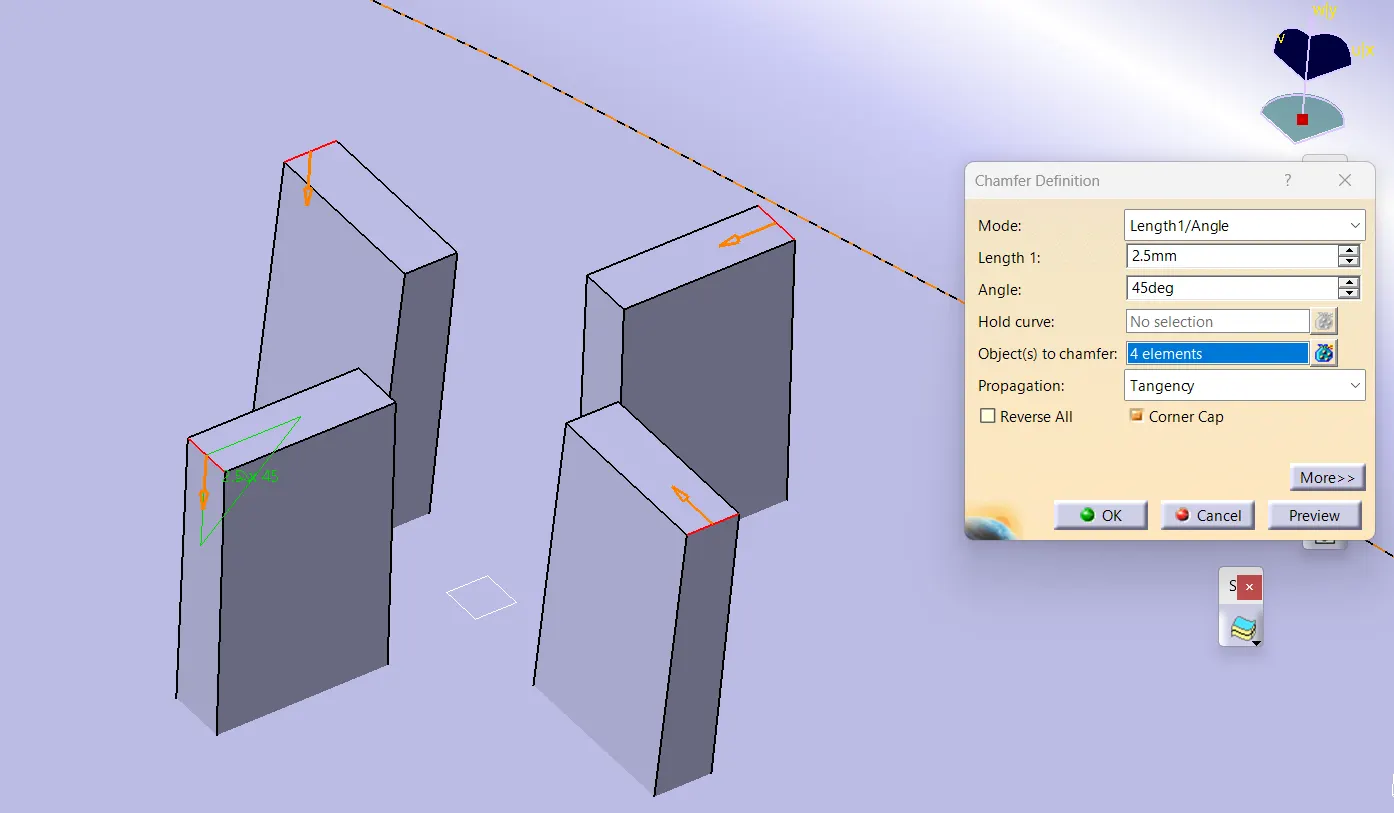
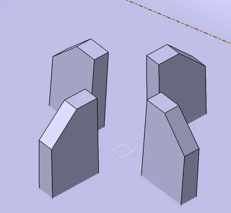
- Perform CHAMFER as shown
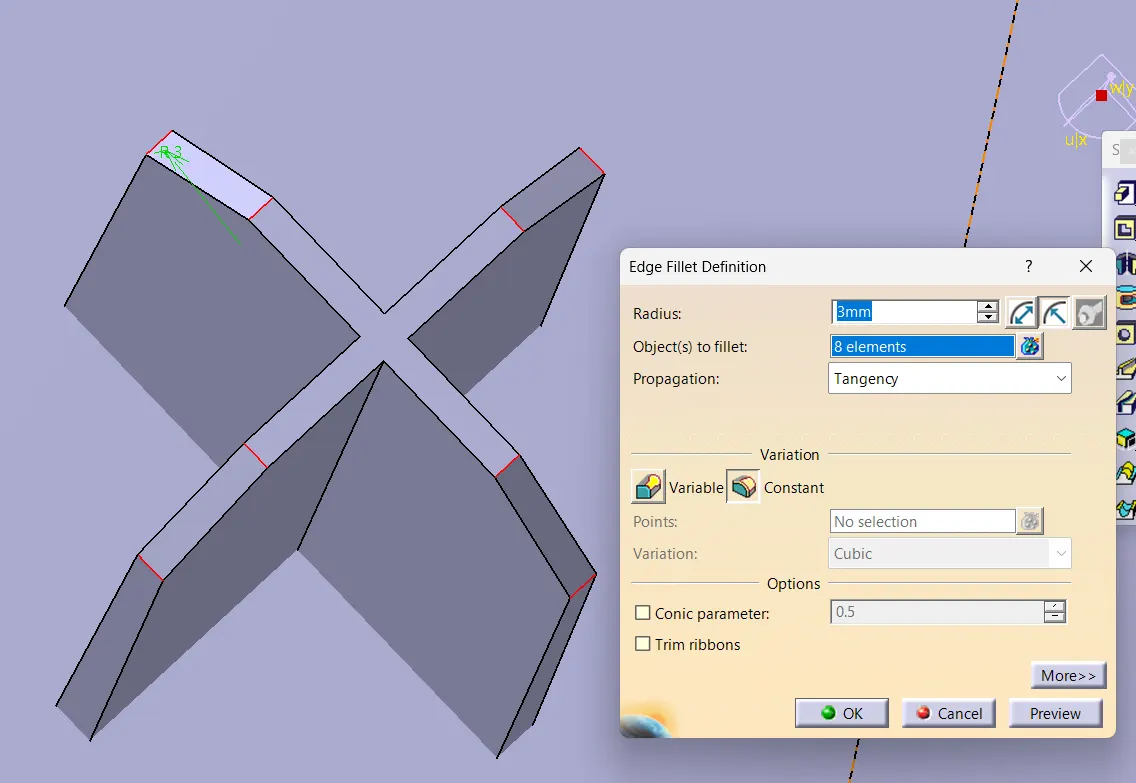
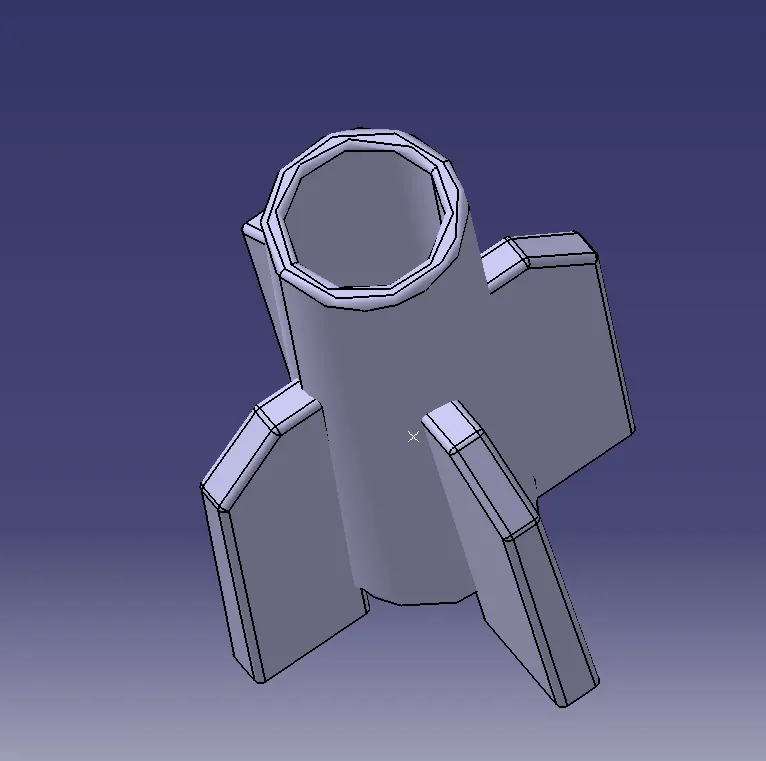
- Perform EDGE FILLET as shown
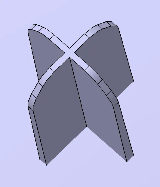
- Now again perform EDGE FILLET as shown
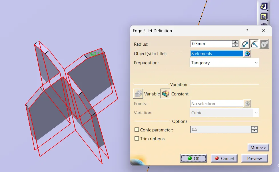
Complete View of 4 way Locator
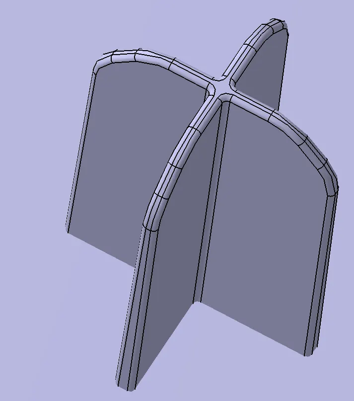
- This is th First Locator created . Now either you can create another 4 Way Locator at another place or " TRANSLATE " it .
- To translate it to another desired place , First copy the first 4 Way Locator from tree structure and Right click the parent of entire component and then select the "Paste special " and then select
" as result with link " .
- TRANSLATION----> POINT-POINT method -----> select the point by which you have created first 4 way locator sketch -----> select another point where you want to translate

- Perform " UNION TRIM " boolean operation individually and then " select the faces to keep " so that there should not be any structure below the door trim solid part .Similarly , repeat it for other .
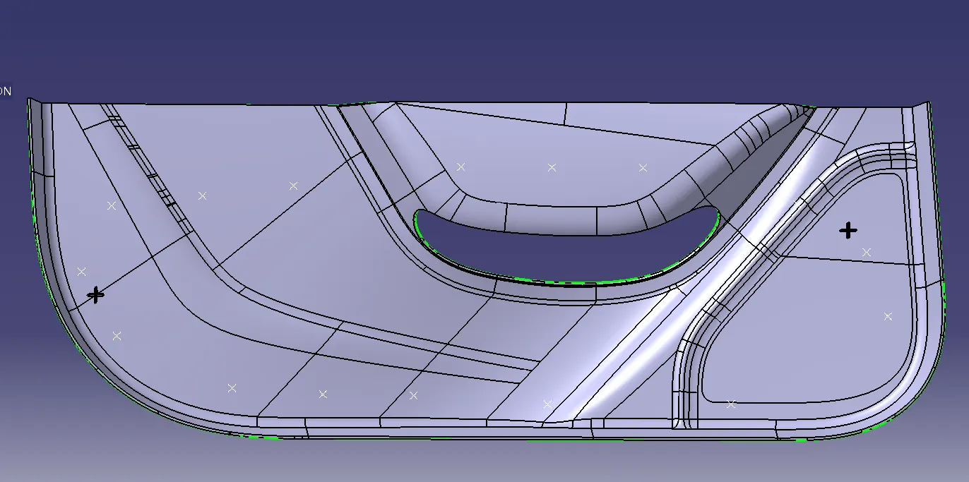
2) PROCEDURE TO CREATE HEAT STAKES
We'll create Heat Stakes at points provided as shown below .These points were provided with the Class A surface only for the creation of Heat Stakes as shown .
If not provided , do extract using Tangent continuity on the outer boundary of the final component . Now create points using Points Repetition by changing Instances depending on the length of the extract.
Now using Parallel Curve , offset the extract to a certain distance and again create points using Points Repetition on the parallel curve by changing Instances depending on the length of the parallel curve of the extract .
- Now create a positioned sketch on plane (created for construction of locators ) using points specified for Heat stakes as shown
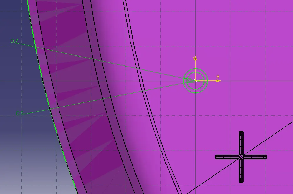
- Insert Body and perform PAD as shown
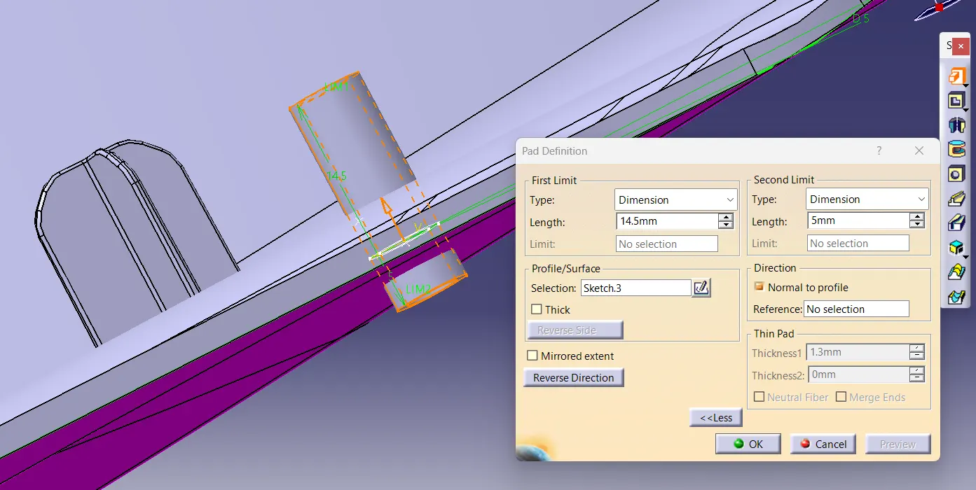
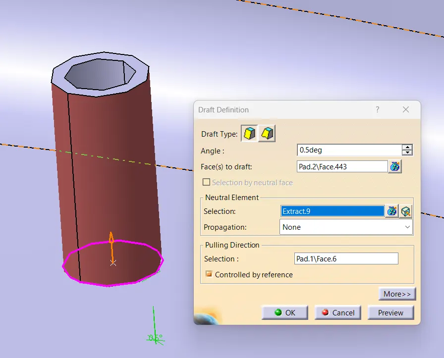
- DRAFT DEFINITION
Apply draft on inner and outer faces by 0.5 degrees using neutal element as extract created for construction of Heat stakes
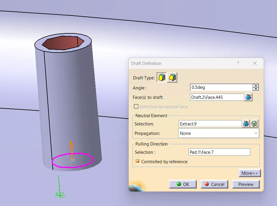
- EDGE FILLET
Use edge fillet pn inner and outer edges either by 0.5mm or 0.25mm
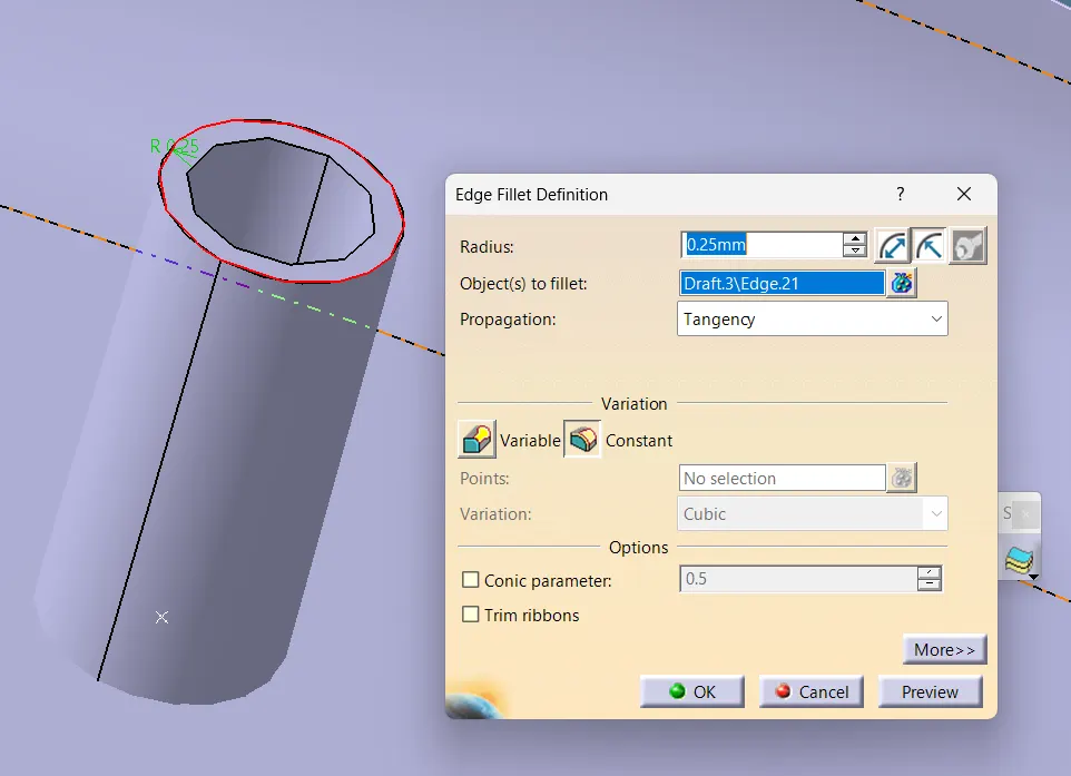
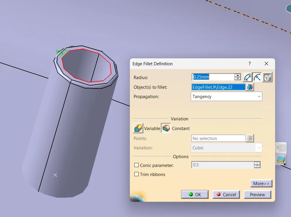
PROCEDURE TO CREATE GUSSETS FOR THE HEAT STAKES:
Gussets are Support Features that Reinforce Areas such as Walls or Bosses to the floor. Just as bridge beams and columns are supported at their vertex with gussets to add critical strength to the structure, the same concept applies to plastic injection moulding.
The difference between Ribs and Gussets is that ribs are usually thin wall supports added internally around walls to achieve better geometry and support. Gussets, on the other hand, are thicker wall supports to add strength and reinforcement to existing plastic features.
Recommended Thickness of a Gusset at the Wall is 50% of the Wall Thickness. Typically, the gusset height is less than four times the wall thickness, preferably two times the wall thickness.
- create sketch as shown below
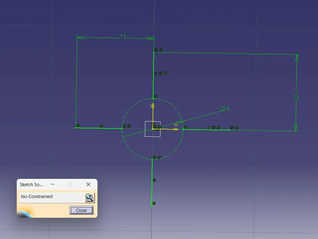
- PAD it as shown
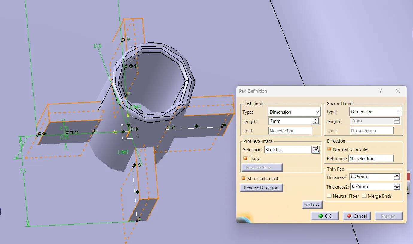
- DRAFT DEFINITION
- CHAMFER DEFINITION
- EDGE FILLET DEFINITION
DRAFT ANALYSIS ON FINAL COMPONENT WITH ENGINEERING FEATURES
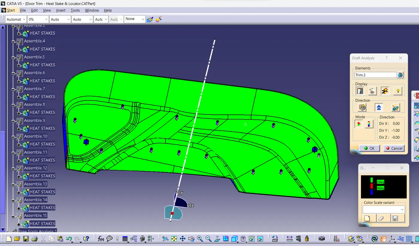

- Screenshots of the completed design in various orientations (Isometric, Front, Side, and Top View)
ISOMETRIC VIEW
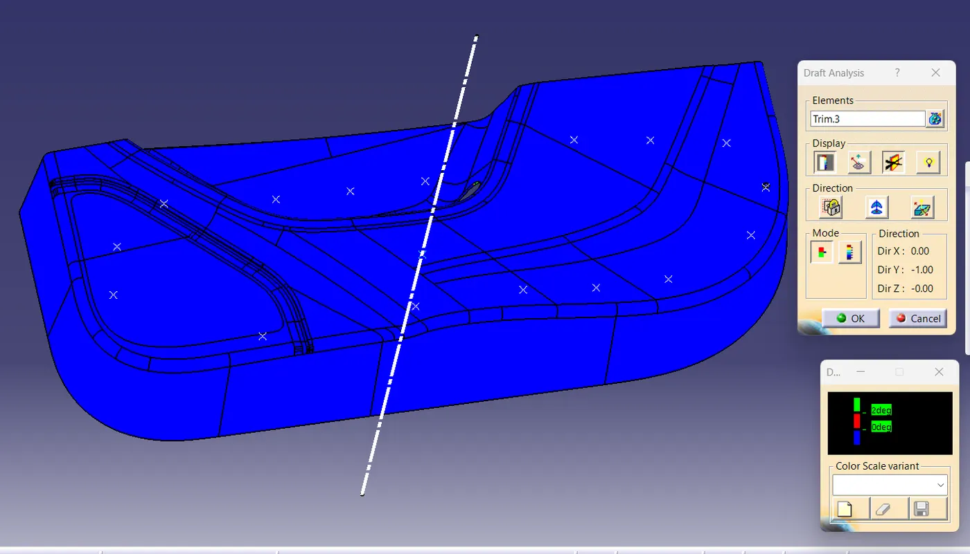
FRONT VIEW
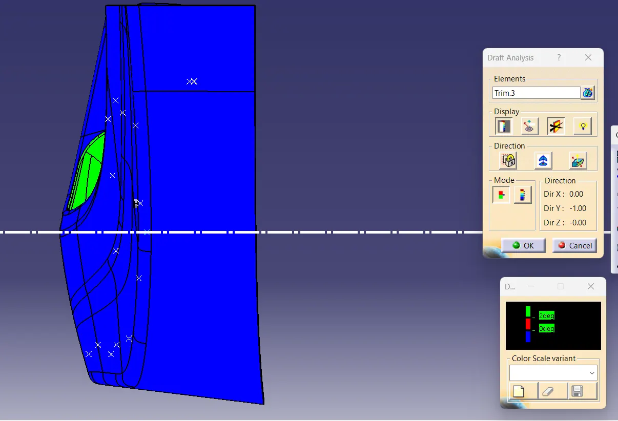
SIDE VIEW
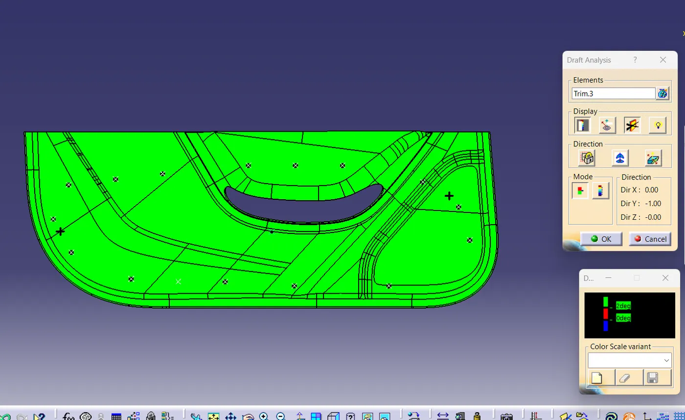
TOP VIEW