Fender Design
AIM : To
i)create the drip area using the mastersection given
ii)Design a front fender from the given skin data and the master section provided with Drip mounting, A-pillar, Sill, Bumper and Baffle (splash) Mounts according to the engineering standards learned
ii)Prepare a report by explaining about Fender Design and its different mounts , manufacturing process and its design parameters
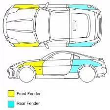
Fender
- Fender is the US English term for the part of an automobile (vehicle body) that frames a wheel well (the fender underside).
- Its primary purpose is to prevent sand, mud, rocks, liquids, and other road spray from being thrown into the air by the rotating tire.
• When vehicle is moving, tyres pick up stones and others and hurl them in all directions. Fenders are basically present to prevent any injuries to pedestrians and contain the motion of these particles
- Most passenger automobiles have four fenders, one over each wheel. For vehicles with a narrow car body that exposes the tire, the fender is an exposed curve over the top of the tire. For wide body vehicles that cover the tire, the fender forms the wheel well surrounding the tire, and is not directly visible from above the car body.
• Wheel wells tend to be much larger than the diameter of the tire, because they do not move with the tire suspension and consequently must be large enough to allow the full range of tire motion on the suspension without touching the interior of the wheel well.

TYPES OF FENDERS :
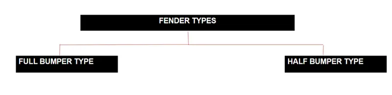
There are two types of fenders , they are
1) Full bumper type
2) Half bumber type
1. FULL BUMPER TYPE: These types of fenders were used in earlier models of vehicles. They contribute to the major increment of the steel weight by just covering the front headlights with respect to the bumper region. The problem associated with this kind of fender is there is a lot of wastage in the blank and every inch of a material is a cost to the industry.
2. HALF BUMPER TYPE: These fenders are mainly used for serving the purpose of cost-cutting and reducing enough proportions of the steel wait resulting in a reduction of the weight of the vehicle slightly. They can be economically manufactured, i.e by slightly increasing the blank size, we can produce two fenders at a time.
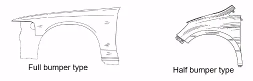
- Presently we are using the half bumper type , the reason for choosing the half bumper type is that when we choose the full bumper type the blank used for creating it is very large and also has the lot of wastage(scrap) , but in the case of the half bumper type we have the possibility to reduce the scrap . This is what we called as scrap management
- In half bumper type we reduce the usage of the steel material and uses the lots of plastic on the bumper which in term decreases the cars weight and increases the performance
FENDER WHEEL ARCH :
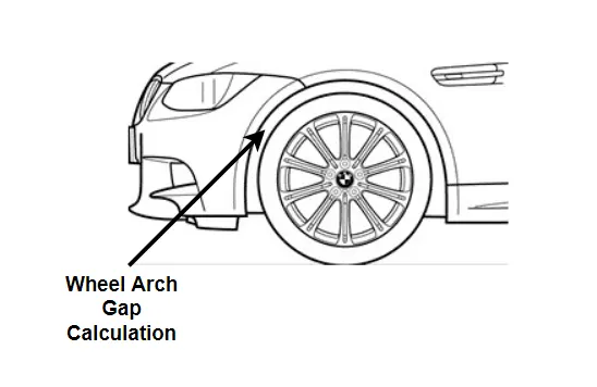
- Fender wheel arch is having some standard specifications , for example if you see the car from the front, if you see the wheel outside fender it does more chipping and it causes lots of damage to the pedestrians and also to the car
- In order to maintain the pedestrians safety we have to position the tire wheel inside the fender
- For the European requirement the clearance between the wheel and the fender outer most skin is 5mm
- This requirements changes from country to country based up on the road conditions
Mounting Regions on Fender :
There are 5 Mounting Points in a Fender
They are
- Body
- A Pillar
- Sill
- Cowl
- Drip
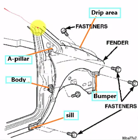
Drip area :
- It is the important mounting unit of the fender . It is connected with the engine compartment , therefore the lot of design constraints are to be followed while designing the fender
Sill Mounting :
Sill is the panel directly below the bottom of the door supporting the floor and may be used to combine the floor and the body . The bottom end of the fender is mounted on the sill body for reinforcement of the fender panel , thus the sill mounting position is designed with holes and emboss . M5 fasteners are used to fix the fenders on the sill body.
Bumper Mounting:
Bumper mounting area is used to fix the plastic bumper to the fender with the help of the fasteners
A-Pillar Mounting :
The A -pillar is the structural pillar that combines the body to the roof . this make the sides of the windshield rest . front fenders are fastened to the A -pillar to form a robust structure
Baffle Mounting :
Baffle mounting or mudguard are clip fit type of mounting on the inner side of the fender arch over the Tyre . It protects the car engine compartment and pedestrians from causing injuries from chip out debris on the road when the car is in motion . they are mounted on the fender using a special type of locking clips which are made up of plastics .
DESIGN METHODOLOGY :
Given data :
1) Drip area Mounting
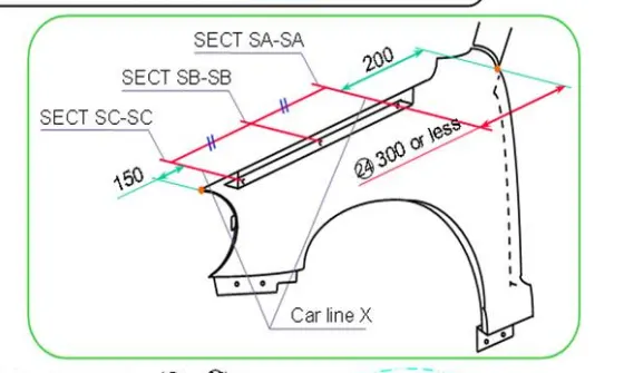
- While designing the drip area we have to initially leave 200-300 mm for cowl top
- For placing the headlamp we have to leave at least 150 mm at the front while designing the fender
- Cowl top part consists pf wiper motor and its instruments
- Two darts are added on the longer side of the drip area in order to provide the stiffness and adds strength to the part . This helps the fender to not to vibrate and impact the forces outside of the fender during motion of the vehicle.
- Embossing are provided on the mounting to strengthen them during fastening.
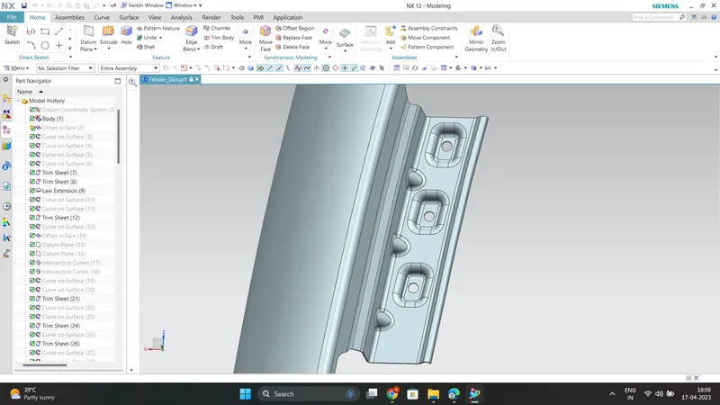
2)Sill Mounting :
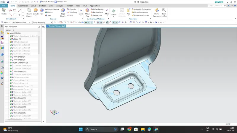
3)Bumper Mounting :
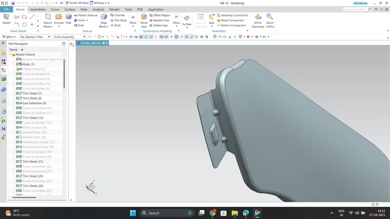
4)A-Pillar Mounting :
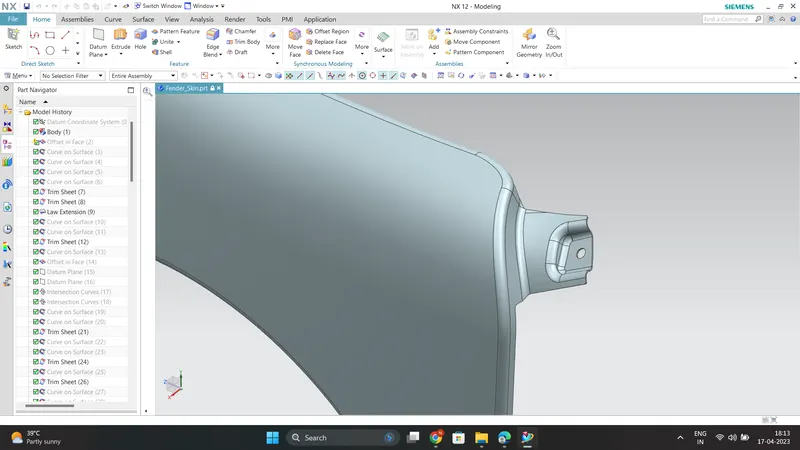
5)Baffle Mounting:
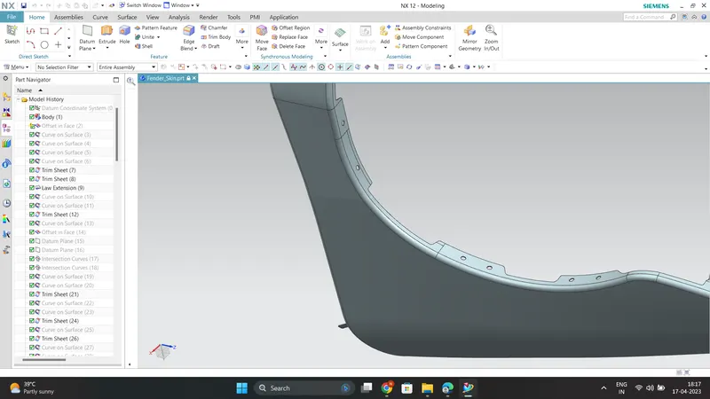
The thickness of 0.75 mm inward on the final sewed surface of the fender is applied .
Manufacturing processes :
The various Manufacturing processes are
1)Stamping :
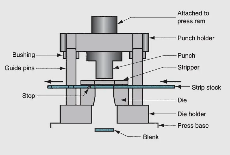
The working components are the punch and die, which perform the cutting operation. They are attached to the upper and lower portions of the die set, respectively called the punch holder(or upper shoe) and
die holder (lower shoe). The die set also includes guide pins and bushings to ensure proper alignment between the punch and die during the stamping operation. The die holder is attached to the base of the press, and the punch holder is attached to the ram. Actuation of the ram accomplishes the pressworking operation.
In addition to these components, a die used for blanking or hole-punching must include a means of preventing the sheet metal from sticking to the punch when it is retracted upward
after the operation. The newly created hole in the stock is the same size as the punch, and it tends to cling to the punch on its withdrawal. The device in the die that strips the sheet metal
from the punch is called a stripper. It is often a simple plate attached to the die with a hole slightly larger than the punch diameter.
For dies that process strips or coils of sheetmetal, a deviceis required to stop the sheet metal as it advances through the die between press cycles. That device is called a stop.
Stops range from simple solid pins located in the path of the strip to block its forward motion, to more complex mechanisms synchronized to rise and retract with the actuation of
the press.
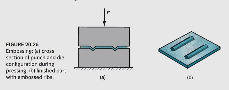
2)Embossing :
Embossing is a forming operation used to create indentations in the sheet, such as raised (or indented) lettering or strengthening ribs . Some stretching and thinning of the metal are involved. This operation may seem similar to coining. However, embossing dies possess matching cavity contours, the punch containing the positive contour and the die containing the negative; whereas coining dies may have quite different cavities in the two die halves, thus causing more significant metal deformation than embossing.
3) Bending:
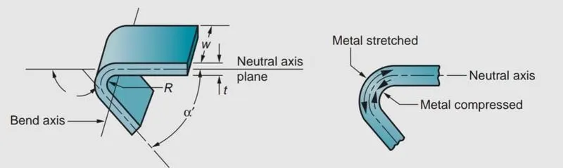
Bending in sheet-metal work is defined as the straining of the metal around a straight axis . During the bending operation, the metal on the inside of the neutral plane is
compressed, while the metal on the outside of the neutral plane is stretched. The metal is plastically deformed so that the bend
takes a permanent set upon removal of the stresses that caused it. Bending produces little or no change in the thickness of the sheet metal.
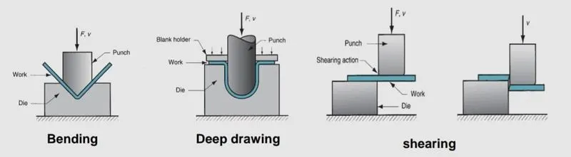
Bending operations are performed using punch and die tooling. The two common bending methods and associated tooling are V-bending, performed with a V-die; and
edge bending, performed with a wiping die.
In V-bending, the sheet metal is bent between a V-shaped punch and die. Included angles ranging from very obtuse to very acute can be made with V-dies.
V-bending is generally used for low-production operations. It is often performed on a press brake and the associated V-dies are relatively simple and inexpensive.
Edge bending involves cantilever loading of the sheet metal. A pressure pad is used to apply a force to hold the base of the part against the die, while the punch forces the
part to yield and bend over the edge of the die. In the setup edge bending is limited to bends of 90degrees or less. More complicated wiping dies can be
designed for bend angles greater than 90degrees. Because of the pressure pad, wiping dies are more complicated and costly than V-dies and are generally used for high-production work.
4)Deep-Drawing:
In this operation, forming of a flat metal sheet into a hollow or concave shape like a cup, is performed by stretching the metal in some regions. A blank-holder is used to clamp the blank on the die, while the punch pushes into the sheet metal. The sheet is drawn into the die hole taking the shape of the cavity.
Stages in deep drawing:
(i) As the punch pushes the sheet, it is subjected to a bending operation. Bending of sheet occurs over the punch corner and die corner. The outside perimeter of the blank
moves slightly inwards toward the cup center.
(ii) In this stage, the sheet region that was bent over the die corner will be straightened in the clearance region at this stage, so that it will become cup wall region. In order to
compensate the presence of sheet in cup wall, more metal will be pulled from the sheet edge, i.e., more metal moves into the die opening.
(iii) Friction between the sheet and the die, blank holder surfaces restricts the movement of sheet into the die opening. The blank holding force also influences the
movement. Lubricants or drawing compounds are generally used to reduce friction forces.
(iv) Other than friction, compression occurs at the edge of the sheet. Since the perimeter is reduced, the sheet is squeezed into the die opening. Because volume remains constant, with
reduction in perimeter, thickening occurs at the edge.
In thin sheets, this is reflected in the form of wrinkling. This also occurs in case of low blank holding force. If BHF very small, wrinkling occurs. If it is high, it prevents the
sheet from flowing properly toward the die hole, resulting in stretching and tearing of sheet.
(v) The final cup part will have some thinning in side wall.
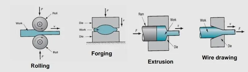
Rolling: In this process, the workpiece in the form of slab or plate is compressed between two rotating rolls in the thickness direction, so that the thickness is reduced. The rotating rolls draw
the slab into the gap and compresses it. The final product is in the form of sheet.
Forging: It is a deformation process in which the work piece is compressed between two
dies, using either impact load or hydraulic load (or gradual load) to deform it.
• It is used to make a variety of high-strength components for automotive, aerospace, and other applications. The components include engine crankshafts, connecting rods,
gears, aircraft structural components, jet engine turbine parts etc.
The workpiece is compressed between two dies containing shaped contours. The die shapes are imparted into the final part.
Extrusion: In this, the workpiece is compressed or pushed into the die opening to produce the desired crossectional shape .
Wire or rod drawing: similar to extrusion, except that the workpiece is pulled through the die
opening to take the cross-section.
Hemming : It is also a manufacturing process (mainly used in case of car Hood) which involves bending the edge of the sheet over on itself, in more than one
bending step.Thisis often done to eliminate the sharp edge on the piece, toincrease stiffness,
and to improve appearance.
Conclusion :
Thus the design of a front fender from the given skin data and the master section provided with Drip mounting, A-pillar, Sill, Bumper and Baffle (splash) Mounts according to the engineering standards learned
is successfully completed by following required design parameters .