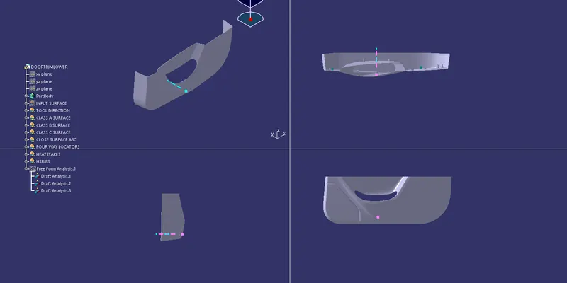
Week 10 - Challenge 3 - Door Trim Lower with Engineering Features
AIM:TO CREATE B SIDE ATTACHMENTS LIKE HEAT STAKES AND FOUR WAY LOCATORS
STEP 1:CHECK THE CONNECTIVITY OF CLASS A SURFACE
To begin with we ensure the connectivity of CLASS A surface uisng join command and check for whether there is any sharp edges are there on the surface that needs to be removed.For this surface there was none and joined it using join command
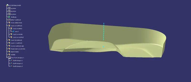
STEP 2:TOOLING AXIS CREATION
A point on surface A is created and a line in the suitable diection is created from the point using point direction option.Then a draft analysis on CLASS A surface is performed to check whether the tooling direction is right or not.
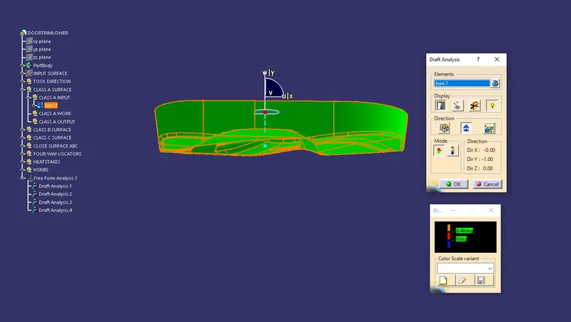
STEP 3:CLASS B SURFACE CREATION
For creating CLASS B surface the input we need is CLASS A surface output and we offset the CLASS A surface output to the desired thickness distance of 2.5mm.Then the patches that need to be repaired in the CLASS B offset surface is repaired using the tool multi-section and by the help of boundary tool and curve smooth tool.Then keep it as the B output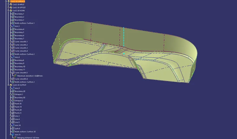
STEP 4:CLASS C SURFACE CREATION
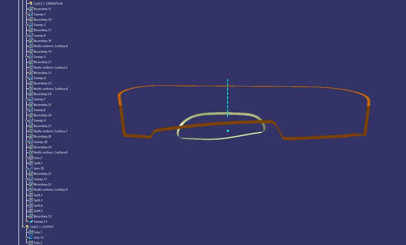
For CLASS C syrface creation the input is CLASS A surface itself.On CLASS A surface we create the C surface part by part using tools like multi-section and sweep(with reference surface and also with draft direction).Necessary repairs on CLASS A surface for the creation of CLASS C is also carried out and also the parts where CLASS C and CLASS B is not intersecting,there in CLASS B surface extrapolation is carried out.
STEP 5:CLOSURE SURFACE CREATION
To create a closure surface,Trim between B&C and then join the part with the latest A available after every repair works.
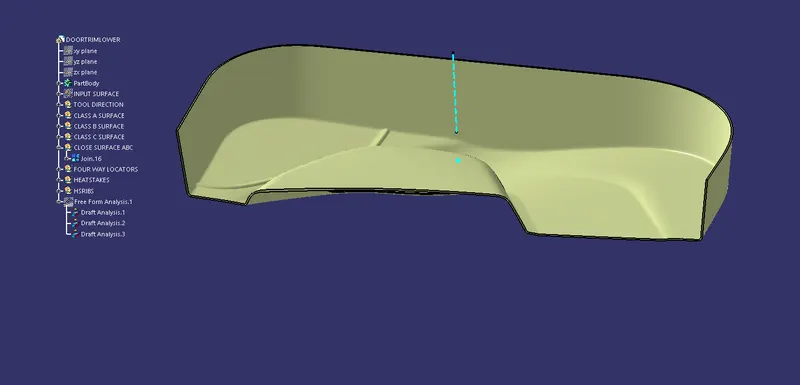
Then using close surface tool in part design make this closure suface into a solid body and if needed draft analysis can be perofrmed on this as well
STEP 6:FOUR WAY LOCATORS AND HEATSTAKES
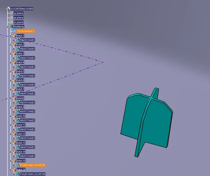
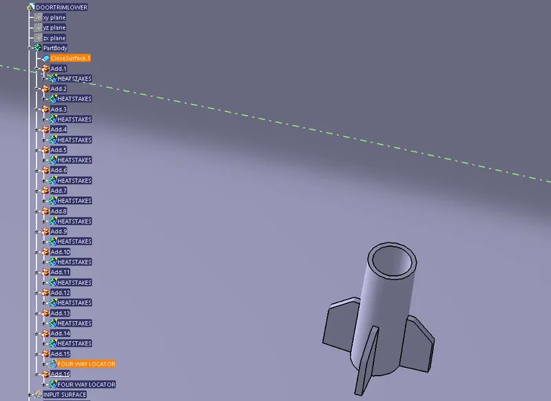
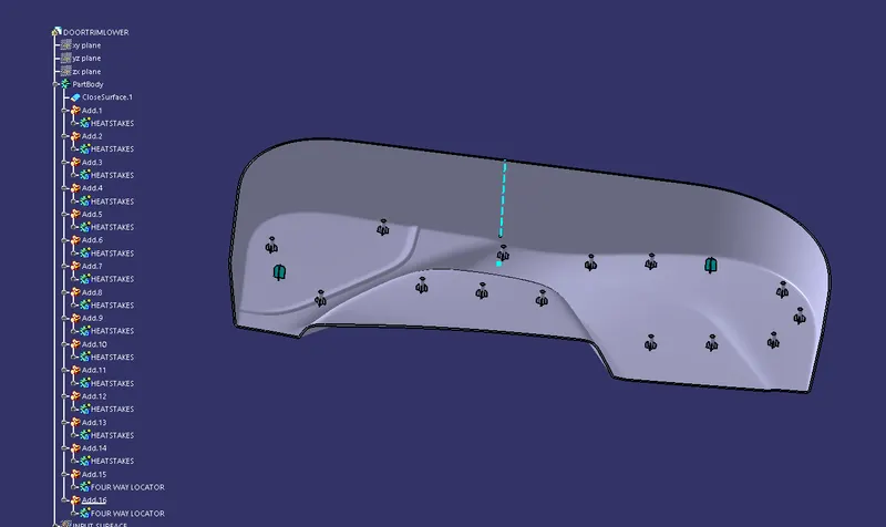
For creating 4-way locators insert a diff.geometrical set and draw a sketch accordingly and pad it using thick option to desired height and apply draft,chamfer and fillets as needed and finally translate it by creating a copy of the body to the desired locations the same procedure shall be repeated for the heatstakes as well and produce the required number of heatstakes and translate accordingly.Then add it to the close surface already created.Draft angle of 0.5 is applied and fillets is given as suited.
STEP 7:DRAFT ANALYSIS
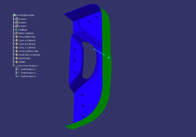
Draft analysis is carried out along the already made tooling axis for the final component.
DIFFERENT VIEWS