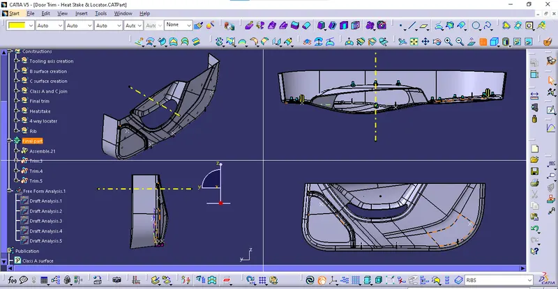
Week 10 - Challenge 3 - Door Trim Lower with Engineering Features
Tooling axis creation :
- First I publish the class A surface then I try to find which method is suitable to create a tooling axis.
- In that given part bisecting method is not needed.
- So I simply create the point on the flat surface.
- Then create the line on the point by point and direction.
- And I perform the draft analysis with that line.
- It clear the draft so I rename the line into Tooling axis.
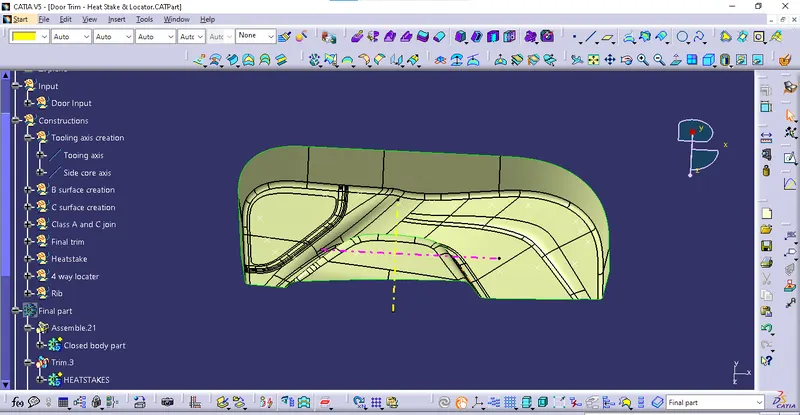
Draft analysis for class A surface :
- First change the view in to customize material mode.
- Then click the draft analysis select the compass and pick and drop on the tooling axis.
- And click on the surface.
- Change the draft value into 3deg.
- It clearing the draft analysis.
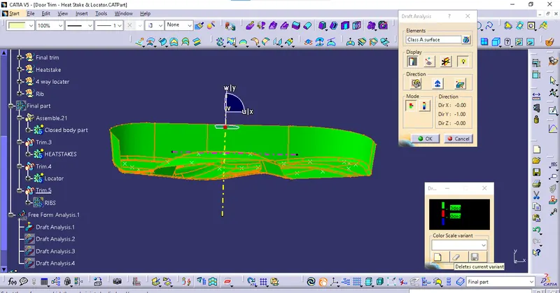
Class B surface creation :
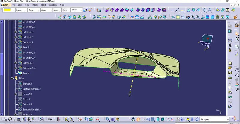
- First I offset the class A surface 2.5mm, it create some patches.
- So I multiple extract the class A surface into 4 part.
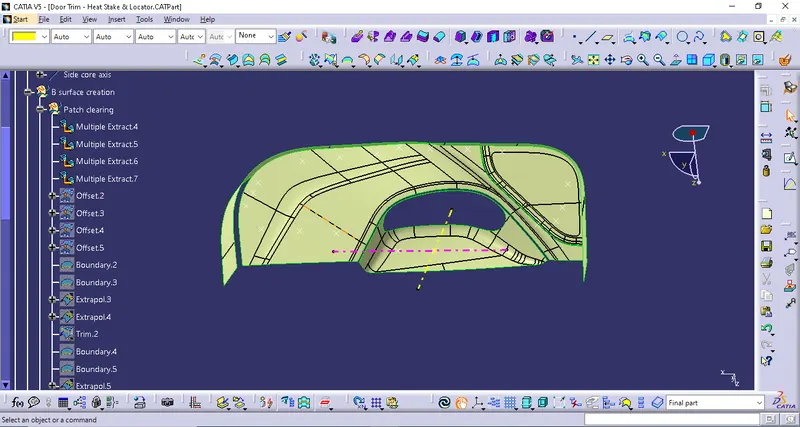
- Then offset the extracts at 2.5mm.
- Create the boundary over the gaps then extrapolate the surfaces intersecting each other.
- Use trim command to trim the surfaces.
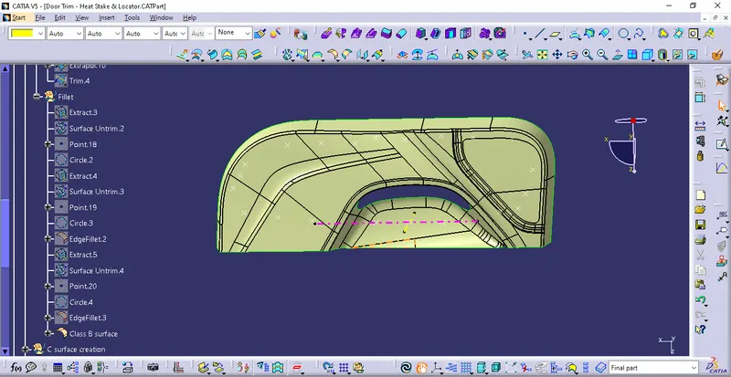
- Measure the fillet value in the class A surface.
- I extract the fillet edges and untrim the extract.
- Create the point on the edge then create a three point circle with point and vertex.
- Use the measure tool vernier to measure the radius.
- Then give the fillet value = Class A fillet value - thickness of the component.
Class C surface creation :
- First create a seperate boundary for which surface is parallel to the tooling axis and which surface is perpendicular to the tooling axis.
- Give the sweep with reference surface for pocket portion of 90deg.
- Use sweep with draft direction of 90deg draft angle for the surface is parallel to the tooling axis.
- Use sweep with draft direction of 3deg draft angle for the surface is perpendicular to the tooling axis.
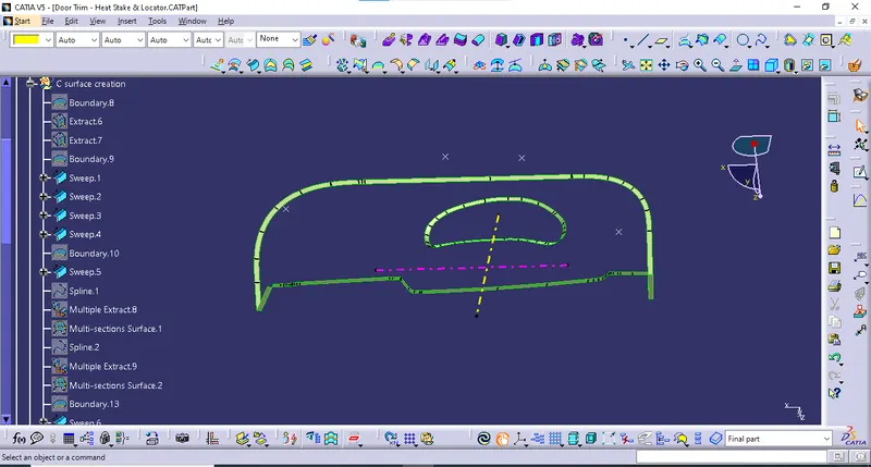
- Some curve edges make problem.
- So I extract the A surface edge and connect edges of sweep by using spline.
- Use multisection surface to fill the gap.
- Click the edges of sweep as a section and click the spline and the extracted boundary as a guild curve.
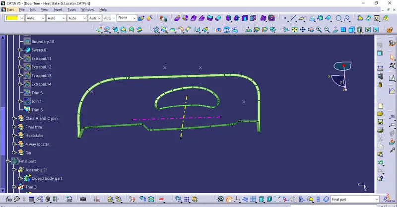
- I trim the sweep of the sweep 1,2 and 3.
- Other sweep and multisection surfaces are connect with the Join command.
- We got the Class C surface.
Class A and C join and Final trim :
- First ensure both the surfaces intersect with each other.
- If that not intersect then extrapolate them to intersect.
- Then make a trim.
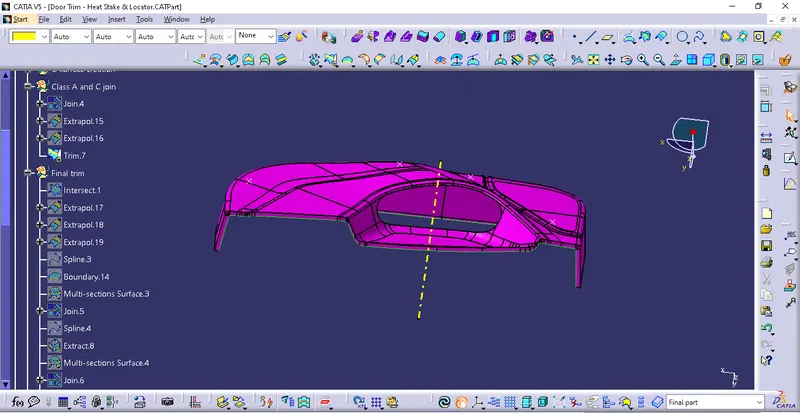
- And trim the Class A,C join and Class B.
- In my case some edges are intersect so I try to extrapolate it, but it doesn't work.
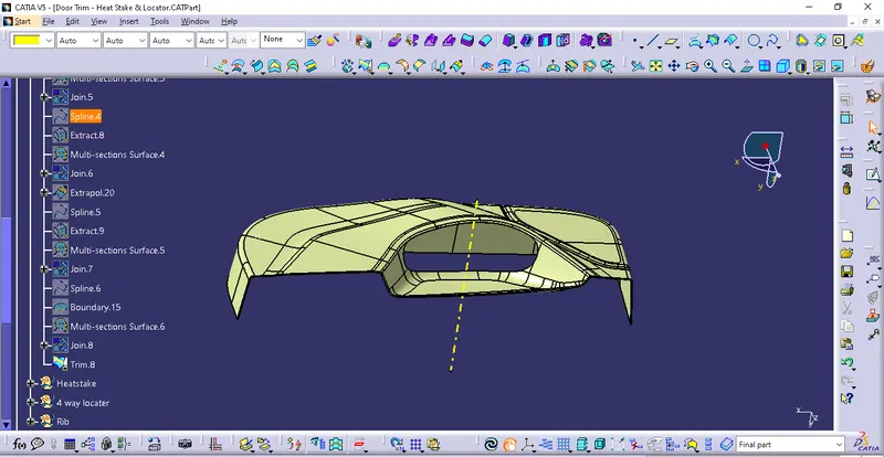
- So I use multisection surface to encounter the problem.
- Then make a final trim to get the closed surface.
Closed part creation :
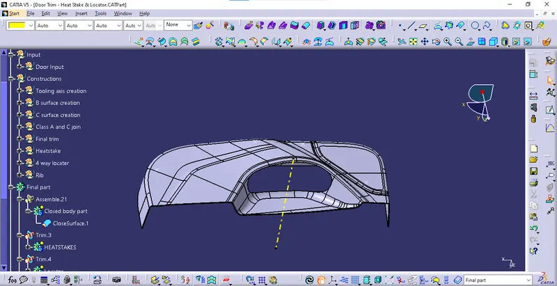
- Insert a new part body to define that working object then change the name of closed body part.
- Jump into part design, click closed suface then select the surface.
- It make a solid component.
Heatstakes creation :
- Insert a new geometrical set and name it as heatstake.
- Create a ZX plane on the given input.
- Then create a position sketch on the plane.
- I create a seperate sketch for a circular portion and ribs.
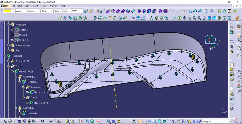
- Then I insert a body and define a working object.
- And pad the circular portion and the rib separately at 20mm for heatstake boss and 10mm for heatstake rib.
- Then draft the rib and boss of 0.5deg of all faces.
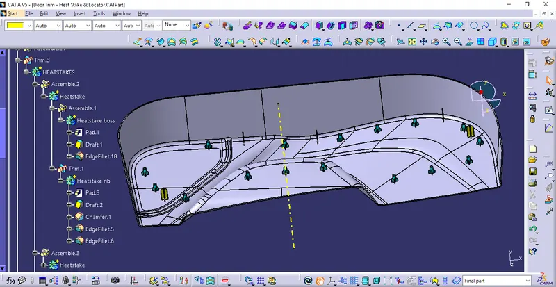
- And give a required minimum fillet and chamfer.
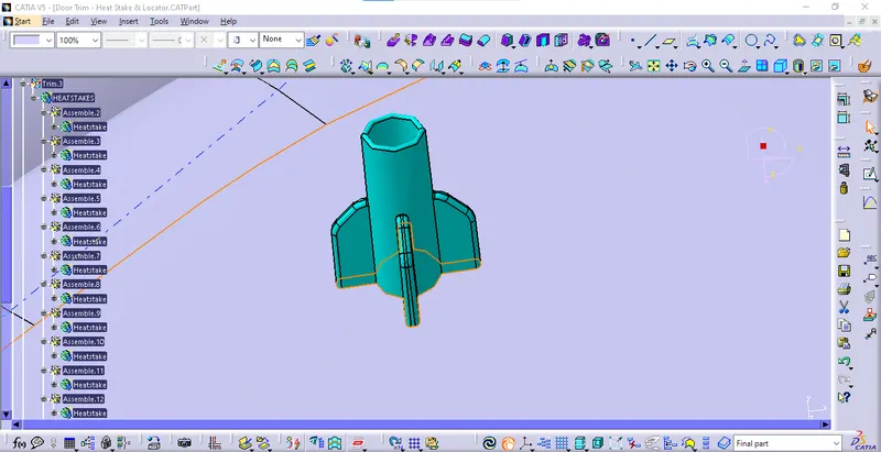
- Copy the heatstake and use paste special as result with link feature.
- Then translate to move that to point to point translate.
- Copy that to move all points which are given in input.
4 way locater creation :
- Insert a new geometrical set and name it as 4 way locater.
- Create a new point on the required surface.
- Then create a plane on the point.
- Create a new sketch on the point.
- I give the length of the locater is 15mm.
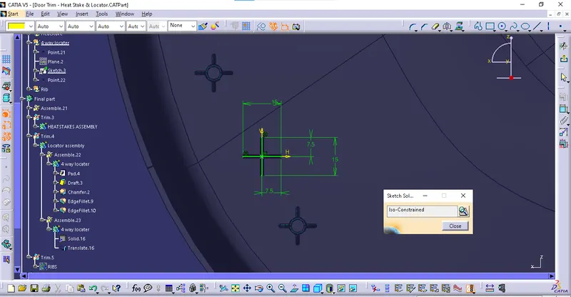
- Insert a new body then pad the locater at 30mm.
- Then draft the all faces at 0.5deg.
- Give the minimum fillet and chamfer on the edges.
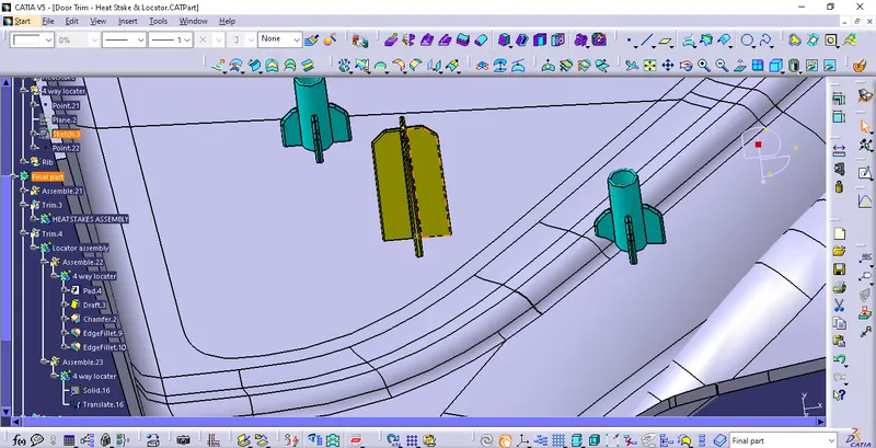
- Copy the locater and paste special as result with link to male separate solid.
- Then move that to required place by point to point translate.
Rib creation :
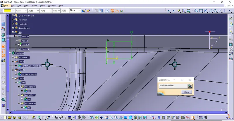
- Create a point on the surface wherever we need the rib.
- Create a sketch of rib in a new geometricalset.
- Insert a new body to pad the sketch of rib.
- Then draft the faces of 0.5deg.
- And create fillet and chamfer on the required place in rib.
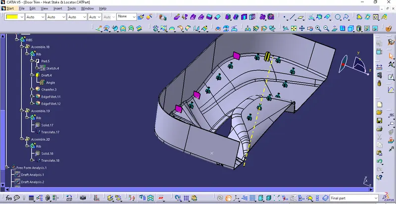
- Copy the rib and paste special as result with link to create a separate solid component.
- Then move to where we want by translate option.
- I do one translate with point to point translate and coordinate type.
Draft analysis of closed surface component :
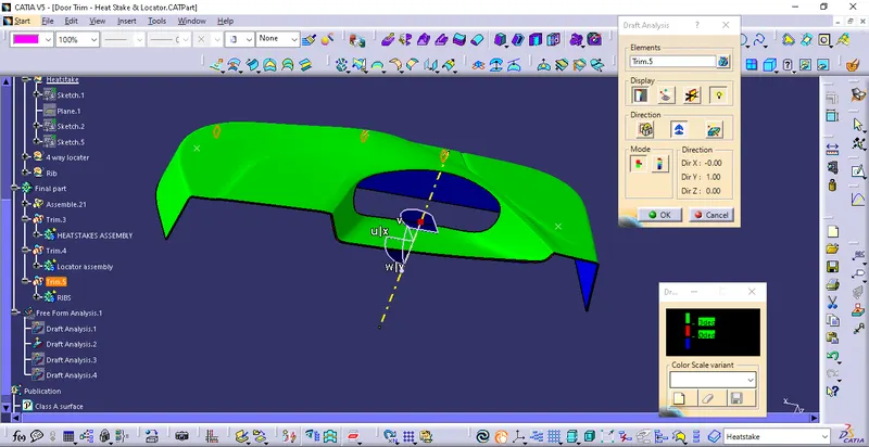
- First change the view in to customize material mode.
- Then click the draft analysis select the compass and pick and drop on the tooling axis.
- And click on the surface of the closed surface component.
- Change the draft value into 3deg.
- It clearing the draft analysis.
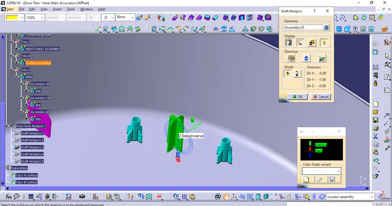
- Same the procedure for 4 way locater draft analysis but the value is 0.45deg.
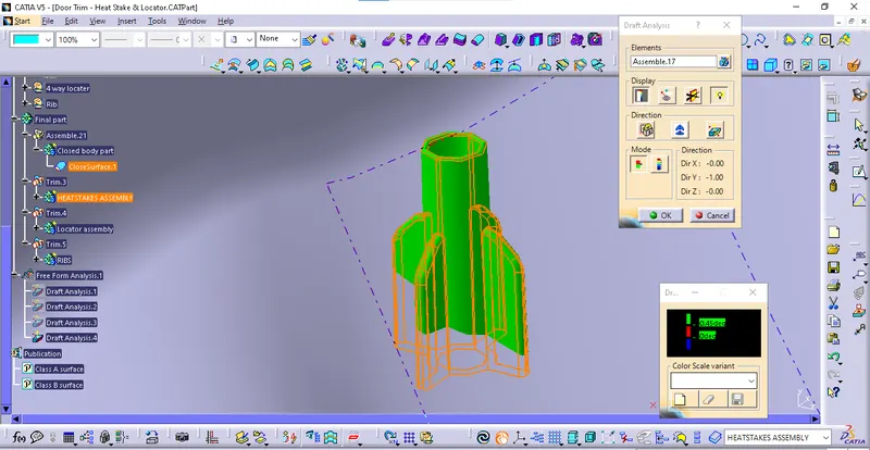
- Below draft analysis for heatstakes.
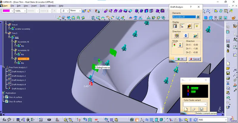
- Draft analysis of ribs :
Front view , Top view , Side view and Isometric view :