Week 10 - Challenge 3 - Door Trim Lower with Engineering Features
DOOR TRIM LOWER WITH ENGINEERING FEATURES
OBJECTIVE: To create the Door Trim Lower Plastic Component from the given Class-A Surface and also creating the Heat Stakes and the Locators by considering the design rules for the Door Applique.
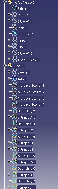
CREATING TOOLING AXIS
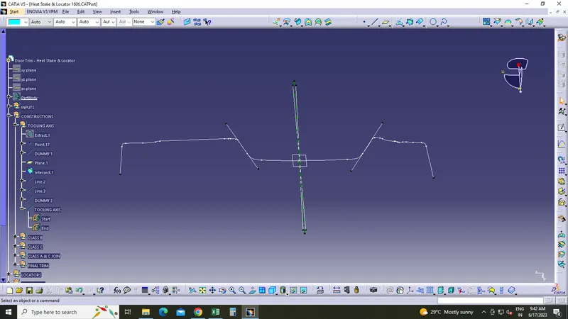
- Tooling axis is created using the bisecting method.
- Extracted the base flat surface of class A and created a reference point.
- Intersected the class A along the xy plane created and drawn 2 lines along the sloped faces.
- Then created a bisecting line for the 2 lines through the reference point and created the tooling axis.
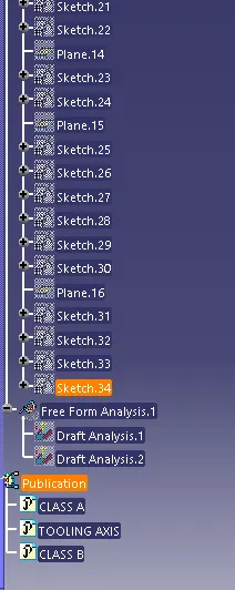
- Published the tooling axis.
DRAFT ANALYSIS ON CLASS A SURFACE
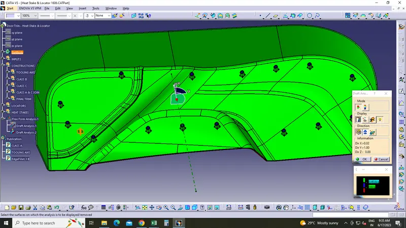
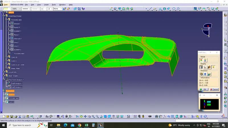
- Changed the view mode to Material mode.
- Insert>Analysis>Feature draft analysis
- Activated the compass and then by dragging the red point, placed the compass along the tooling axis and locked it.
- Clicked on the part and analysed the draft angle of component.
- Considered the min. draft angle as 3 degree.
- The green colour area shows that the component satisfies the given draft angle.
CREATING CLASS B SURFACE
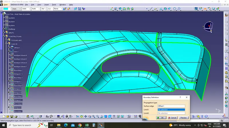
- To create class B surface, the whole class A surface is offseted by 2.5 mm.
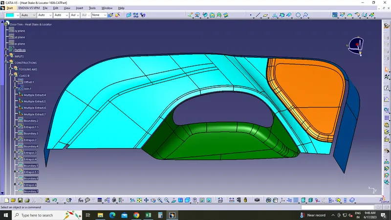
- Some fillet patches were missing.
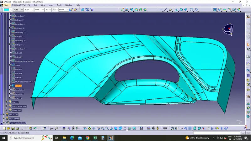
- So i removed all the fillets and extracted the Class B as 4 parts.
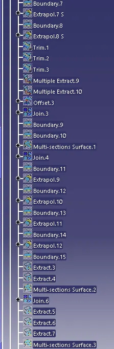
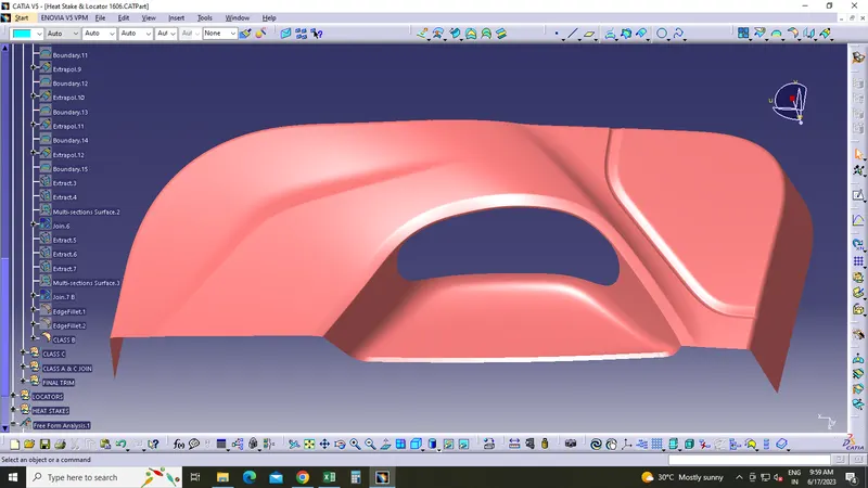
- Then i used the Multiple extract,Extrapolate and Trim commands to work on it and created a complete class B surface.
- All the fillets were given with proper values.
CREATION OF CLASS C SURFACE
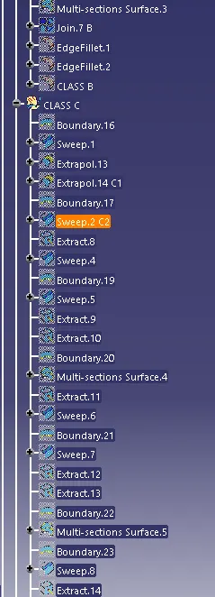
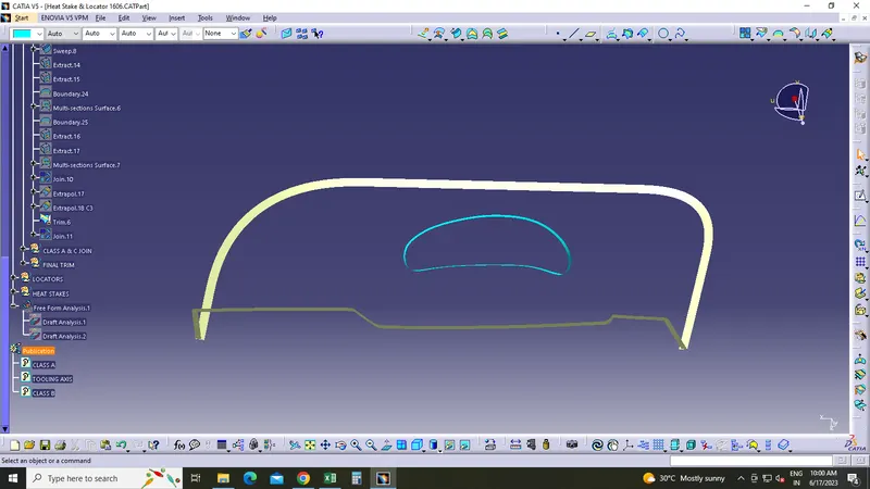
- Using boundary command created separate boundaries on the edges of the class A surface and used the SWEEP command to create class C.
- 3 degree draft were given to the edges which were perpendicular to the tooling axis.
- And some edges were sweeped separately and used the multi section to complete the gaps or filleted edges.Then trimmed the intersecting parts.
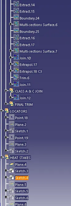
- For the center sweeped c which was not touching any other sweep, used the Join command to join all the C surface together.
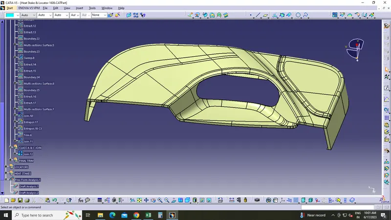
- Then joined the class A and class C surafces together.
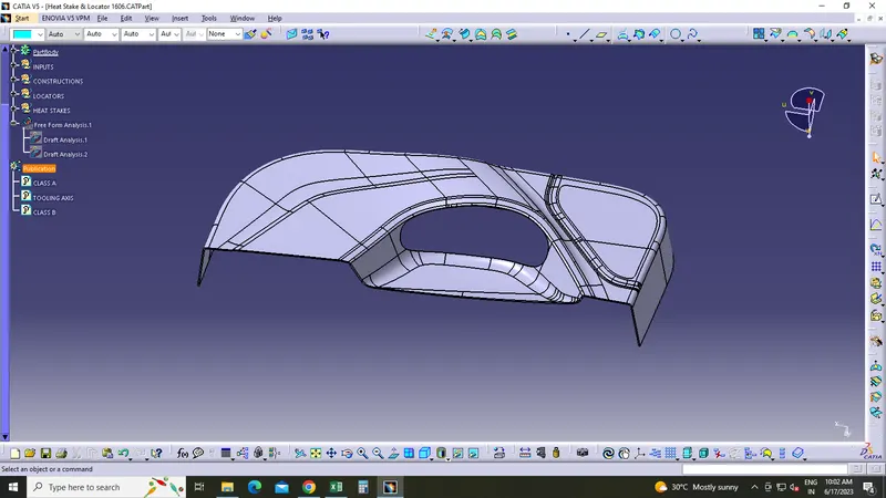
- After that this class A+C join were trimmed with the class B surface to get a closed component.
- Used the boundary command to check whether the component has any open boundaries or not.
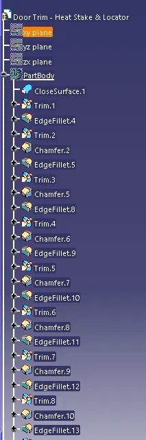
- Then in the part design workbench used the CLOSE SURFACE command to create a solid out of the component.
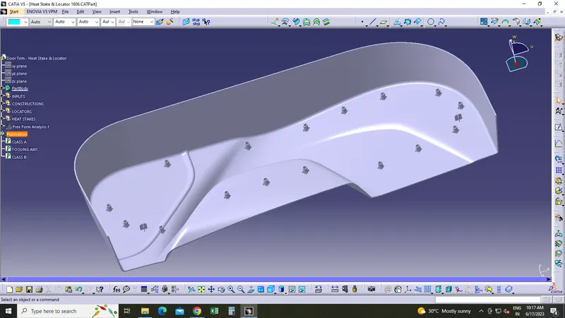
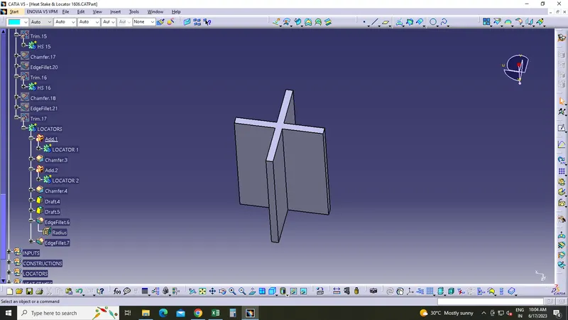
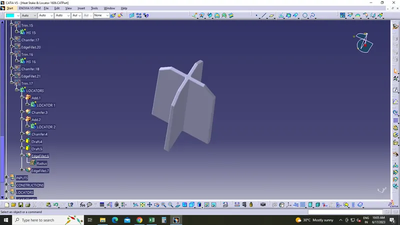
CREATING LOCATORS
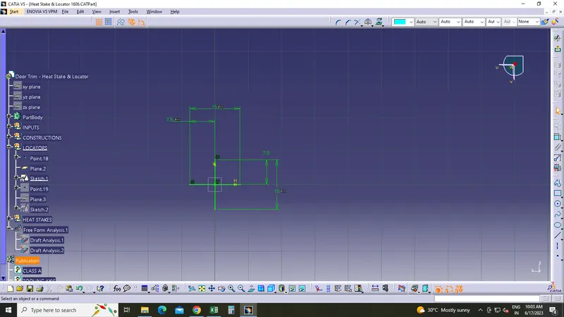
- Created a reference point and a plane tangent to the surface.
- Then a positioned sketch was created on that plane.
- padded the sketch to create the Locator.
- Given 0.5 degree draft to the faces with pulling direction as the Tooling axis.
- Then chamfered the top corners.
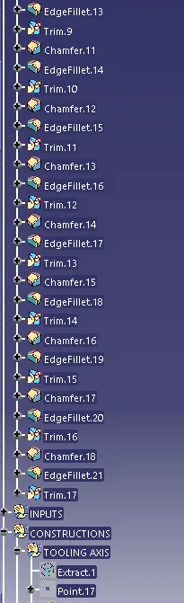
- Using the boolean operation trimmed the locator with the Solid component body.
- Then 0.25mm fillets were provided to the edges of the Locators.
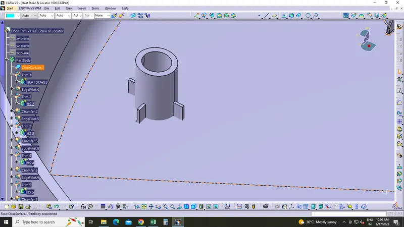
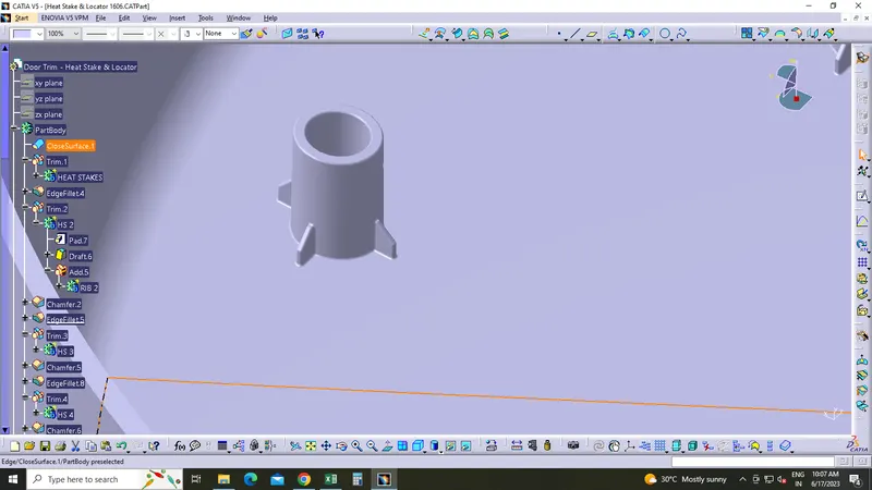
CREATING HEAT STAKES
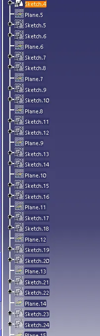
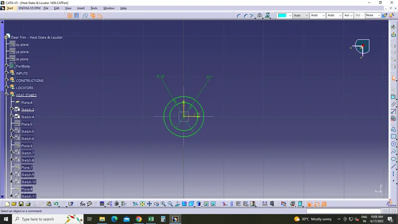
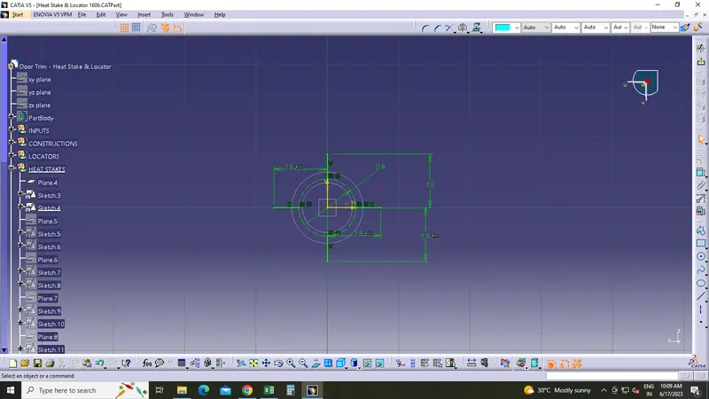
- Basic sketches were made on the planes which were created on the reference points that were already provided with the class A surface.
- Each Heat stake was created separately using pad command.
- 0.5 degree draft were given to all the faces and chamfered the sharp edges of the ribs of heat stakes.
- Using the boolean operation trimmed the heat stake with the Solid component body.
- Then 0.25mm fillets were provided to all the edges.
DRAFT ANALYSIS ON FINAL SOLID COMPONENT
- Draft analysis was performed on the final component in the same method which i used for the draft analysis of class A surface.